Oppervlaktekwaliteit verbeteren bij machinale bewerking: Sleuteltechnieken
De oppervlaktekwaliteit van machinale bewerking verwijst naar de oppervlaktegesteldheid van het onderdeel na machinale bewerking. De...
Clamping during assembly is usually achieved through assembly fixtures. An assembly fixture refers to the process equipment used in assembly to apply external force to parts to ensure their reliable positioning. It includes simple and portable general-purpose fixtures and special fixtures on assembly frames.
There are four methods of fastening components with assembly fixtures: clamping, pressing, pulling, and pushing (or expanding), as shown in Figure 5-34.
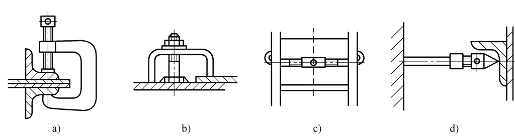
a) Clamping
b) Pressing
c) Pulling
d) Pushing
Assembly fixtures can be divided into manual and non-manual fixtures based on the source of clamping force. Manual fixtures include screw fixtures, bar fixtures, lever fixtures, eccentric fixtures, etc.; non-manual fixtures include pneumatic fixtures, hydraulic fixtures, magnetic fixtures, etc. This section mainly introduces commonly used manual fixtures.
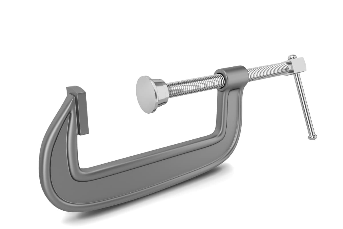
A spiral clamp uses the relative motion between a screw and a nut to transfer external force to fasten parts, featuring multiple functions such as clamping, pressing, pulling, pushing, and supporting.
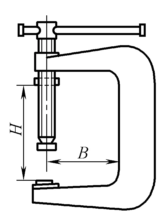
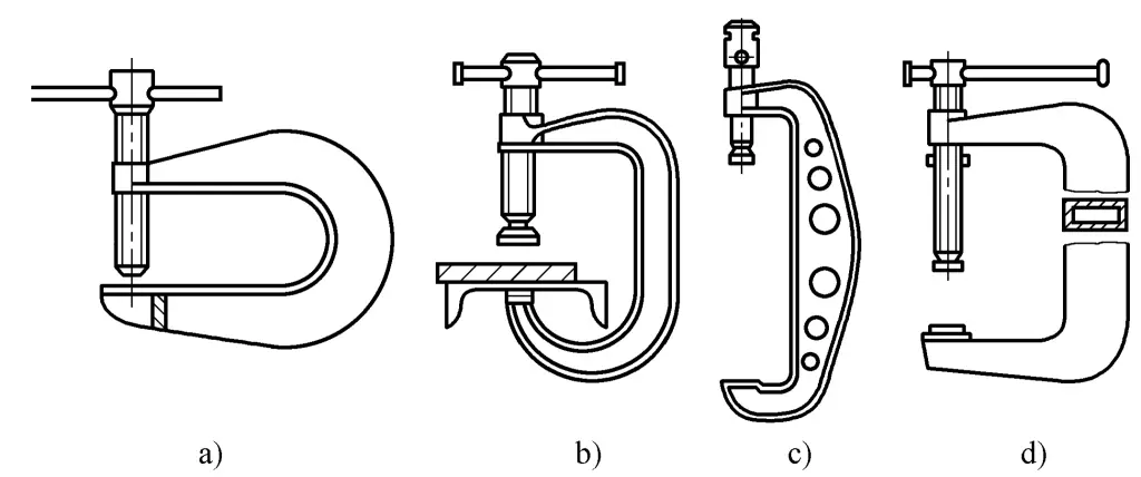
A bow-shaped spiral clamp uses a screw for clamping action. When selecting or designing a bow-shaped spiral clamp, its working dimensions H, B should be adapted to the dimensions of the clamped parts as shown in Figure 5-35, and it should have sufficient strength and stiffness. On this basis, the weight of the bow clamp should also be minimized for ease of use. Commonly used bow-shaped spiral clamps include the structures shown in Figure 5-36, with smaller ones typically using the structures shown in Figures 5-36a and 5-36b, while larger bow-shaped spiral clamps often use the structures shown in Figures 5-36c and 5-36d.
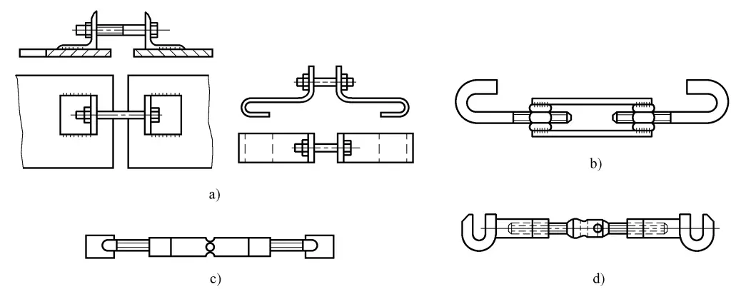
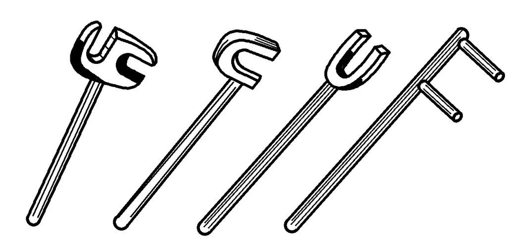
A spiral tensioner uses a screw for tightening action, and its structure can vary. As shown in Figure 5-37a, a simple spiral tensioner tightens by rotating the nut. The tensioners shown in Figures 5-37b and 5-37c have two independent screws with opposite thread directions, and the nuts are connected with thick flat steel or round steel. Rotating the nut adjusts the distance between the screws, achieving a tightening effect. If the end of the screw with a rectangular plate is welded to the workpiece, it can also serve for positioning and supporting. Figure 5-37d shows a double-headed bolt tensioner, where rotating the bolt adjusts the distance between the two hooks to tighten the parts.
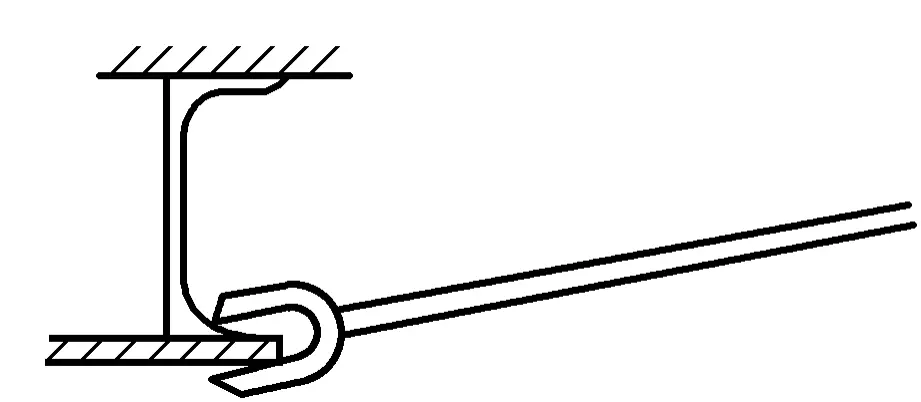
As shown in Figure 5-38, spiral compressors are usually temporarily welded to the workpiece using brackets, and then use screws to compress. Figure 5-38a shows the use of a “┌” shaped bracket spiral compressor to level the plate seam during butt jointing. Figure 5-38b shows the use of a “Π” shaped bracket spiral compressor to compress parts.
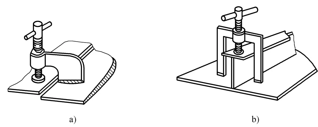
a) Using a “┌” shaped bracket spiral compressor to level the plate seam
b) Using a “Π” shaped bracket spiral compressor to compress parts
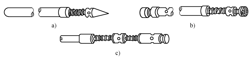
Spiral supporters are used for jacking or spreading, not only in assembly but also in correction operations. Figure 5-39a shows the simplest type of spiral jack, consisting of a screw, nut, and round tube. The head of this type of spiral jack is pointed, which is not conducive to protecting the surface of the parts and is only suitable for supporting surfaces where precision is not highly required, such as thick plates or larger steel shapes. Figure 5-39b shows an added pad at the head of the screw, which does not damage the workpiece and is not prone to slipping when jacking or supporting. Figure 5-39c shows a spiral supporter, which has left and right threads at both ends of the screw, speeding up the jacking and supporting actions.
Wedge clamps use the inclined surface of the wedge to transform external force into clamping force, thereby achieving the purpose of clamping parts. Figure 5-40 shows two basic forms of clamping with wedges; Figure 5-40a shows direct action on the workpiece, not only requiring the clamped workpiece surface to be relatively smooth and flat, but also the wedge is prone to scratching the workpiece surface; Figure 5-40b shows the wedge transmitting the force to the workpiece through an intermediate element, improving the contact situation between the wedge and the workpiece surface.
To ensure that the wedge clamp can self-lock during use, the wedge angle α should be less than its friction angle, generally using 10°~15°. If it is necessary to enhance the effect of the wedge clamp, an appropriate thickness of shim can be added under the wedge.
Figure 5-41 shows several uses of the wedge clamp. Figure 5-41a shows the use of a wedge mouth clamp plate to directly clamp the profile steel and plate material. Figure 5-41b shows the use of a “∏” shaped clamp plate combined with a wedge to clamp parts. Figure 5-41c shows a wedge clamp with an embedded plate, where the cross-sectional shape of the wedge can be rectangular or circular.
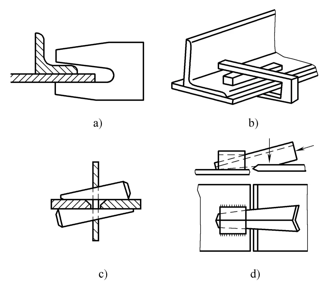
This clamp is mainly used for aligning plate materials, because it uses a wedge plate, so it can only be used when there is a gap at the joint of the plate materials. The angle steel wedge clamp shown in Figure 5-41d is also commonly used in assembly.
Lever clamps utilize the force-multiplying effect of levers to hold or press parts. Because they are simple to make, convenient to use, and highly versatile, they are widely used in assembly, as shown in Figure 5-42. Figure 5-43 shows several commonly used simple lever clamps in assembly. Additionally, pry bars are also often used as lever clamps.
Eccentric clamps use an eccentric part whose center of rotation does not coincide with its geometric center to clamp. Eccentric clamps used in production are divided into circular eccentric wheels and curved eccentric wheels based on the shape of the working surface. The former is easier to manufacture and more widely used. Eccentric clamps generally require self-locking capability.
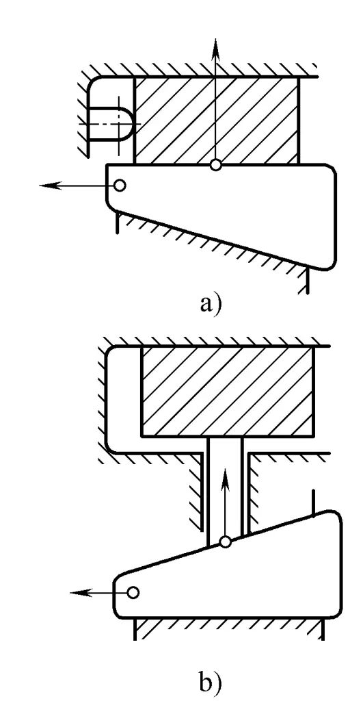
Figure 5-44 shows an eccentric circular wheel fixture, where the eccentric circular wheel with an eccentric hole is mounted on a fixed shaft and can rotate around the shaft. The distance e between the center of the circular eccentric wheel and the axis is called the eccentricity, and the circular eccentric wheel is equipped with a handle for operation. When the eccentric wheel rotates around the shaft, the crossbar rotates around the pivot, thereby clamping the workpiece. Figure 5-44a shows a spring as the pivot, while Figure 5-44b shows a fixed pin shaft as the pivot.
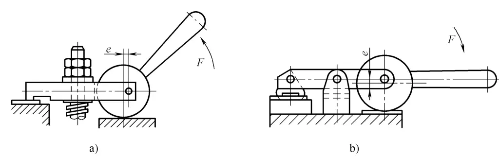
The advantage of the eccentric fixture is its quick action, but the disadvantage is that the clamping force is small, and it can only be used in situations with no or little vibration.