Oppervlaktekwaliteit verbeteren bij machinale bewerking: Sleuteltechnieken
De oppervlaktekwaliteit van machinale bewerking verwijst naar de oppervlaktegesteldheid van het onderdeel na machinale bewerking. De...
Shearing is a stamping process that separates sheet or coil material along a straight or curved line using specialized shearing equipment.
As a preparatory step in stamping production, shearing is essential because most raw materials for processes such as punching, bending, drawing, and forming are supplied in large sheets or coils. These materials must be sheared to the required dimensions, creating strips or blocks suitable for subsequent operations.
Consequently, large enterprises with the necessary resources typically establish dedicated stock preparation workshops or sections to centralize shearing tasks, facilitating production management and the efficient use of raw materials.
Depending on the production volume and the geometry and size of the blank, shearing can be performed using different methods:
Manual shearing involves using hand shears or manually operated bench shears. This method is mainly suitable for small-scale production or when only a few items are needed. It can only shear sheet metal thinner than 0.8mm; its advantage is simplicity, as it can accommodate different sizes and curves. However, it is labor-intensive and has very low production efficiency.
Machine shearing of sheet and coil material using specialized equipment is a widely adopted method. The main shearing machines are plate shears (straight-knife shears) and disc rolling cutter shears (commonly known as slitting machines). These specialized machines greatly reduce labor, increase production efficiency, and ensure quality.
Handheld vibration shears are a type of small electric tool that is flexible to operate. They are primarily used for slicing and segmenting coiled plates, and the resulting shear line can be straight or curved. This method is suitable for nesting materials. Nesting cylindrical pieces for deep drawing can increase the material utilization rate by about 5%, which is economically significant for valuable materials.
Shearing edge forms can be categorized as straight-edge shearing, angled-edge shearing, and roller shearing.
Straight-edge shearing refers to the process of separating sheet or coil materials using two parallel blades (see Figure 2-9). This method of shearing can only be performed along a straight line. It is suitable for shearing sheet and coil materials that are narrow but relatively thick.
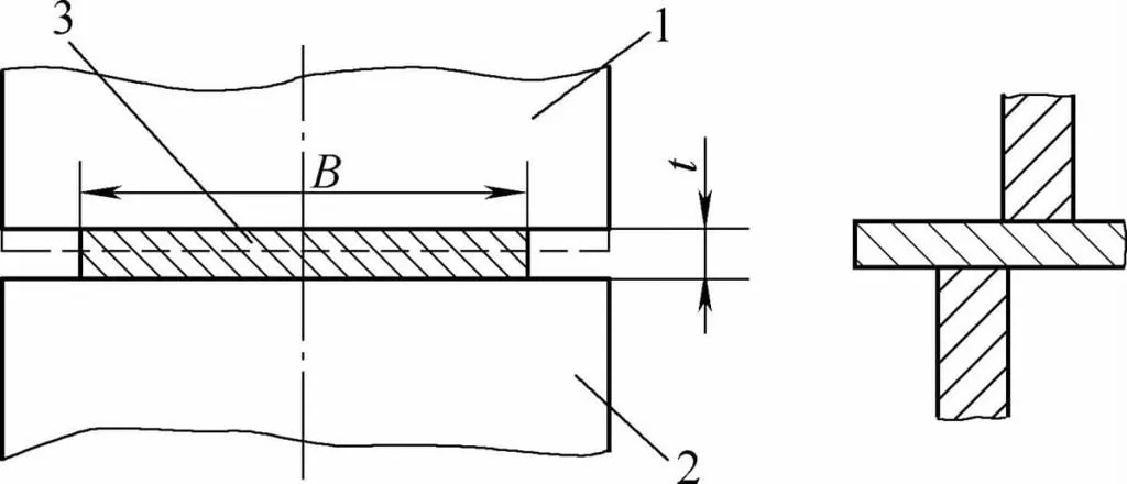
1-Upper Blade 2-Lower Blade 3-Sheet Metal
The shearing process of straight-edge shearing can be divided into three stages:
When shearing starts, the upper blade first contacts the sheet material and applies pressure to it. This pressure increases from zero to the elastic limit, causing the material to undergo elastic deformation, as shown in Figure 2-10a. If the pressure is removed at this point, the sheet material will return to its original state.
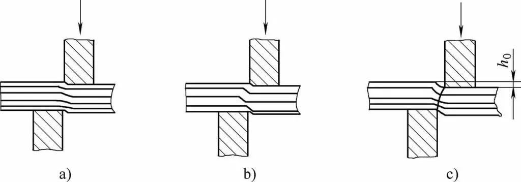
a) Elastic Deformation Stage
b) Plastic Deformation Stage
c) Fracture Stage
As the upper blade continues to descend, the pressure exerted by the shearing edge on the material increases. When the pressure on the sheet material exceeds the elastic limit, the sheet material undergoes local plastic bending deformation. At the same time, the edge of the upper blade begins to press into the sheet material, as shown in Figure 2-10b.
After the upper blade presses into the material to a certain height h, stress concentration occurs, and cracks begin to form at the tip of the shearing edge. As the pressure continues to increase, the cracks rapidly expand, eventually causing the material to fracture into two parts, thus completing the shearing process, as shown in Figure 2-10c.
The quality of the cut surface in flat blade shearing is related to the properties of the material itself and the size of the gap between the upper and lower blades. Generally, the harder the material being sheared, the narrower the shiny area on the cut surface, meaning the shearing process is shorter. Conversely, when the material is softer, the shiny area on the cut surface is wider, and the shearing process takes longer.
Moreover, the gap between the upper and lower blades significantly impacts the quality of the cut surface. An appropriate blade gap can result in a brighter shiny area on the cut surface, with little burring and bending, and a smooth surface of the cut material.
If the gap is too small, it will ruin the fractured part of the cut surface and increase the shearing force. If the gap is too large, the cut material may exhibit severe bending and stretching at the fracture site, leading to burrs on the shearing edge and dimensions that do not meet the requirements.
The size of the blade gap is generally set at 0.02t to 0.05t, depending on the type and thickness of the sheet material.
Angled blade shearing is distinct from flat blade shearing. It refers to the process of shearing sheet or coiled materials on a shear machine where the upper and lower blades intersect at a fixed angle.
Unlike flat blade shearing, where the entire blade contacts the sheet for simultaneous shearing, angled blade shearing only involves a small portion of the blade making contact, gradually performing the cut. This greatly reduces the shearing force compared to flat blade shearing. Shears, hand snips, and benchtop manual shears all employ angled blade shearing techniques.
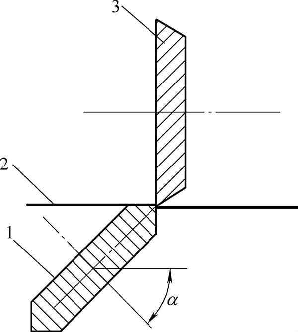
As shown in Figure 2-11, the shearing process begins with only a portion of the upper blade making contact with the sheet. Then, a crack forms along the edge of the sheet, and as the shearing continues, the crack opens up with the downward movement of the upper blade, gradually separating the sheet into two parts. The material deformation principle at each stage is essentially the same as in flat blade shearing.
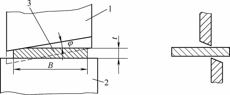
1 – Upper Blade, 2 – Lower Blade, 3 – Sheet Metal
In angled blade shearing, the working stroke of the upper blade is much larger than in flat blade shearing. The stroke value is determined by the shearing length and the shear angle φ. During the process, due to the presence of the shear angle, the sheet not only undergoes the same deformation as in flat blade shearing, but also bends downward due to the pressure of the upper blade.
This leads to deformation, twisting, and stretching of the sheet, which is the biggest drawback of angled blade shearing. However, because it reduces the shearing force, it is the most commonly used shearing method in stamping production. It is often used for shearing sheet and coiled materials that are wide and thin.
The shear angle φ can reduce the shearing force, making the shearing work smooth and gradual. However, to prevent the sheet from sliding out of the blade and bending excessively, the maximum angle should not exceed 12°. The size of the angle φ is related to the thickness of the sheet. Generally, for sheets 3-10mm thick, the angle is 1°-3°; for sheets 10-35mm thick, the angle φ is 3°-5°.
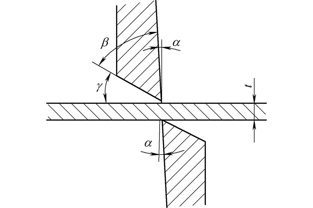
As shown in Figure 2-12, the size of the blade angle β directly affects the strength of the cutting edge, shearing quality, and shearing force. The size of the blade angle β is usually determined by the hardness of the material. When shearing harder sheets, β should be between 75°-85°; when shearing very soft sheets (such as pure copper, aluminum, etc.), β should be between 65°-75°.
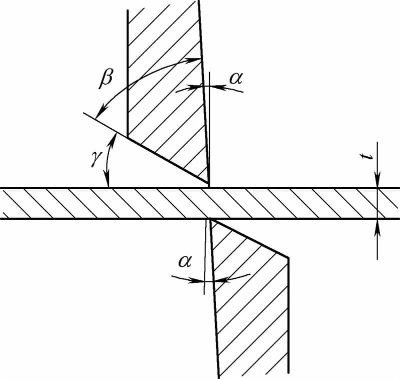
However, when the blade angle β is less than 90°, the sheet will bend under pressure and the sheet will be pushed away from the cut, a phenomenon particularly noticeable for thick and narrow strips that often need to be straightened after shearing.
Therefore, on a typical power-driven shear machine, for the convenience of blade grinding, β is often set at 90°. At the same time, to reduce friction between the upper part of the blade and the sheet, a back angle α should be ground on the blade, usually α is 1.5°-3°.
The shearing force used in flat blade shearing can be calculated by the following formula:
Fflat = KBtτ
Here,
The formula for calculating the shearing force of an angled blade shear is:
Fangled = K · 0.6τ × t2/tanφ
Here, K is the blade dullness coefficient, taken as 1.3; φ is the blade tilt angle (°).
Generally, it is not necessary to calculate the shearing force. You can simply choose according to the main specifications t × B marked on the shear. Here, t indicates the maximum thickness of the sheet that can be sheared, and B indicates the maximum width that can be sheared. However, when designing the shear, the maximum shearing thickness of the sheet is typically based on the shear strength of 25 steel or 30 steel.
Therefore, if the material to be sheared exceeds the design strength, it cannot be used according to the maximum sheet thickness marked on the shear. At this time, the maximum shearing thickness of different materials should be recalculated according to the formula for shearing force.
Roller shearing, also known as disc shearing, is a method of cutting material by passing it between two disc cutters rotating in opposite directions. This technique is often used for longitudinally shearing extremely long sheets or coils, making it a crucial means for material preparation. The principle of this shearing method is illustrated in Figure 2-13.
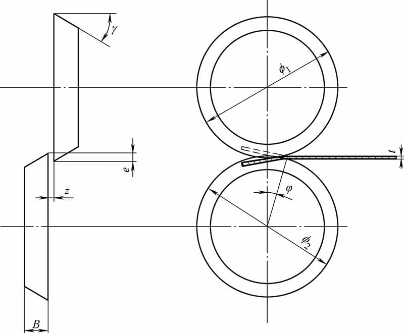
The two axes of the roller shear are usually parallel to each other and to the plane of the material being cut. However, some choose to intentionally design the disc blades to be tilted for curved cutting tasks.
During roller shearing, the material is fed by the friction between the rotating disc cutter and the material. To ensure the normal operation of the cutting process, the contact angle between the blade and the material must be less than 15°. Therefore, when designing the disc cutter, the following formula should be satisfied first:
(φ1+φ2) / 2 ≥ 35t
Typically, the diameter of the disc rolling cutter should exceed 100t.
Additionally, other design dimensions can be set as follows: the staggering amount of the rolling cutter is (0.2~0.3)t; the width of the rolling cutter is 25~30mm; the gap between the rolling cutters is (0.025~0.05)t; the tilt angle of the rolling cutter, α, is 30°~45°.
Notably, when the staggering amount of the rolling cutter is zero or the two rolling cutters are separated, the sheet metal can rotate within the blades and be sheared into workpieces with arbitrary curved edges.
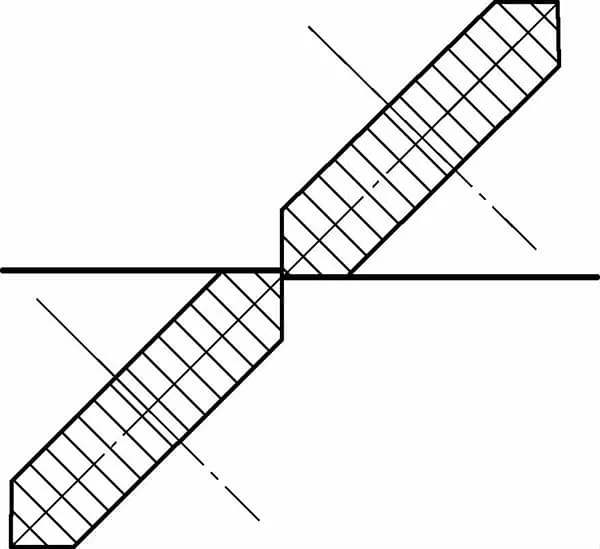
A single-roller wheel shear machine only has one pair of rolling cutters. Due to different configuration angles, it can shear workpieces with various curved or inner hole contour edges. Figure 2-14 shows a disc rolling shear machine with the lower rolling cutter inclined. Figure 2-15 illustrates a disc rolling shear machine with both upper and lower rolling cutters inclined. Both types of rolling shear machines can shear straight and curved workpieces.
1. Lower Cutter, 2. Sheet Material, 3. Upper Cutter.
Roller shearing can be employed for the following tasks:
1) Slitting. A distinct feature of roller shearing is that the cutting line is not constrained by die size, allowing for infinite length. With this principle, multiple pairs of shearing wheels are arranged on the upper and lower shafts. As per the set width, the disc shear can divide the coiled sheet material into multiple parallel strips. The distance between each pair of shearing wheel edges is the width of the strip, as shown in Figure 2-16.
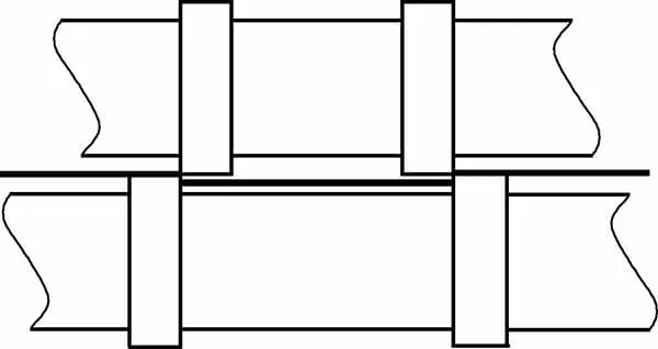
This process is particularly important for conserving material and enhancing work efficiency, especially for some punch-outs with long edges parallel to the feeding direction, which can significantly reduce the ponskracht. During the longitudinal separation process, the roller shear edge exerts some horizontal pulling force on the material.
For strips in the middle of the sheet, the horizontal forces on both sides are balanced, but the outermost shear lines lose this balance, so the outermost pair of shearing wheels should have a shear angle β of about 75°.
2) Shearing of cylindrical and cup-shaped pieces. In stainless steel product manufacturing, shearing is commonly used for trimming the edges of rotationally drawn parts with diameters ≤400mm, as shown in Figure 2-17.
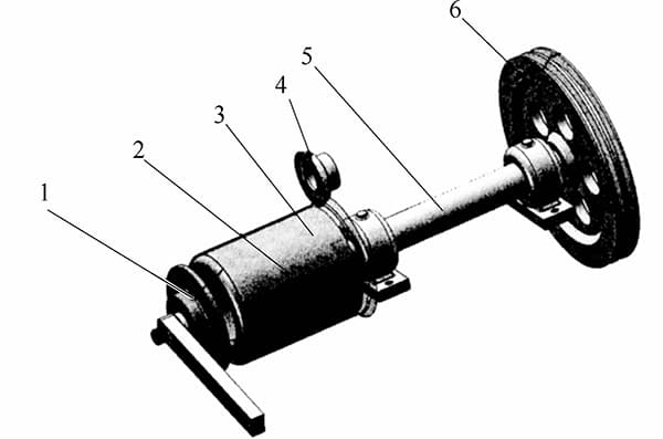
1 – Backstop, 2 – Pressure Wheel, 3 – Workpiece, 4 – Upper Shear Wheel, 5 – Main Shaft, 6 – Belt Wheel
3) Ring shearing of basin-like products. Ring shearing can replace the trimming die of large drawn parts, especially those with diameters greater than 400mm. In ring shearing, the upper and lower shearing wheels replace the punch and die, saving a significant amount of die steel, heat treatment, and metal cutting costs. The larger the diameter of the part being sheared, the more economical it is.
This is because the larger the diameter of the punching die, the thicker the die and its walls, the larger the size of the upper and lower die seats, and the more material consumed. Ring shearing has strong versatility and can save equipment investment, replacing large presses with manual labor (see Figure 2-42).
For example, for a part with a thickness of 1.0mm and a diameter of 800mm, if edge trimming is performed by punching, the material consumption for the whole set of dies is at least 500kg, and the machine tool specification should be above 1500kN.
In contrast, using a lever mechanism for shearing, the disc shearing wheels and brackets can be universal parts, which in a sense can be considered cost-free; from a component perspective, shearing only requires the replacement of one mold core, equivalent to the top plate in punching mold.
From the output perspective, the force on the shearing handle only needs to be about 50N. Comparing the two, the advantages of ring shearing are obvious, especially when the batch size is not large.
4) Ring shearing of flat blank pieces. A major advantage of ring shearing of flat blanks is that the material can directly enter the flanging or edging process after shearing, and the shearing mold does not affect the implementation of the next process. The workpiece only needs to be clamped once to complete the edge trimming, flanging, or edging work, with no issue of re-centering.
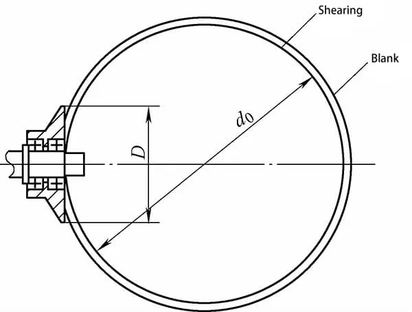
5) Ring shearing has a minimal working diameter issue, that is, the diameter of the pressure shearing wheel should be less than 1/5 of the shear track diameter; otherwise, it will easily lead to uneven shear edges. The diameter of the shearing wheel and the shear track diameter are shown in Figure 2-18.
Shearing wheels can be divided into pressure wheels and load-bearing wheels, also known as upper shearing wheels and lower shearing wheels.
Before heat treatment, the shearing wheel should have the area outside the reserved blade width hollowed out to reduce the amount of heat generated during blade grinding. The radial and axial runout of the shearing wheel should be less than 0.02mm.
The back angle of the pressure wheel blade should be 25°. Leave a straight section or a 3° back angle at the blade edge (0.5~1)t; this can prevent pulling the material during separation. Shearing wheels should generally be designed with double bearings to ensure accurate shear tracks and reliable work. If indeed limited by conditions and only a single bearing can be used, a precision rolling bearing of grade E or above should be adopted.
The formal name for rocking shear is the floating rotary deep-drawing part trimming die (see Figure 2-43). Based on the motion rule of the mass point in the spiral groove, a positional shift occurs between the punch and the die, thereby achieving the separation of the workpiece. The movement of the die in the spiral groove is like a bamboo stick swaying in a stick cylinder, hence this shearing method is known as rocking shear in production.
Unlike blanking, the punch in rocking shear also performs vertical movement, but the shear plane is parallel to the horizontal plane. Therefore, the larger the central angle of the workpiece being sheared, the better, or in other words, the closer the intersection angle between the shear point and the horizontal plane is to a right angle, the better.
Rocking shear is typically used to cut drawn parts where the intersection angle between the shear point and the horizontal plane is greater than 40°, such as deep conical parts, bowl-shaped parts, etc.
Rocking shear comes with its own guide column and guide sleeve, so the precision requirements for the machine tool are not high. It has certain versatility for workpiece size and shape. Workpieces smaller than the maximum die size can be sheared on the same sub-base by changing the die and punch.
As the separation of different quadrants of the drawn part is completed at different stages during the descent of the punch, rocking shear can also use smaller power presses to shear larger workpieces.
The advantage of rocking shear is that it is reliable and the blade edge can be quickly repaired. The disadvantage is that it is relatively difficult to design and manufacture, especially when the workpiece diameter is large. Therefore, this type of shearing is often used for trimming drawn parts with diameters less than 300mm.
The key points for making rocking shear are as follows:
1) The difference in radius e1 between the punch and the workpiece cannot be greater than the eccentricity of the spiral slider. It is best to control it within the range of 2/3 to 4/5 of the slider’s eccentricity (see Figure 2-19), i.e.,
e1≤4/5×e
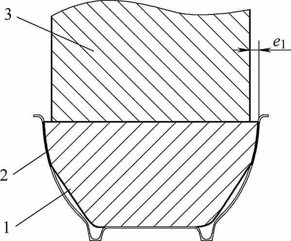
1 – Presser block, 2 – Workpiece, 3 – Punch.
In the formula, ‘e’ represents the eccentricity of the helical slider.
2) The presser core should be adjusted to a height exceeding the unilateral clearance of the die surface.
3) The thread helix angle should be no less than 3.5°.
4) The intersection angle between the slider outline and the axis should not exceed 40° and should be symmetrical along the horizontal centerline, as shown in Figure 2-20.
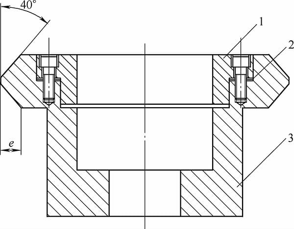
1 – Die, 2 – Adjustment Shim, 3 – Slider.
5) The helical sleeve should be made of die steel with a low-carbon steel heat sleeve, which can enhance the wear resistance and toughness of the die.
6) The diameter of the punch cannot be too small. When the punch diameter is less than 18mm, a stopper post should be installed to share the downward vertical thrust.
7) The working surfaces of the slider and the helical groove should have a relatively low surface roughness value, and maintain good lubrication during operation.
8) When the slider is in motion, it should not collide or interfere with the die holder.