Oppervlaktekwaliteit verbeteren bij machinale bewerking: Sleuteltechnieken
De oppervlaktekwaliteit van machinale bewerking verwijst naar de oppervlaktegesteldheid van het onderdeel na machinale bewerking. De...
The main parameters for TIG welding include welding current, arc voltage, welding speed, tungsten electrode diameter and tip shape, nozzle diameter and gas flow, distance from the nozzle to the surface of the workpiece, and the angle of the welding torch.
There are two types of welding currents: direct current and alternating current. Direct current has two different methods of connection: straight and reverse. The choice of current type and polarity mainly depends on the type of material being welded and the requirements for the weld.
To reduce or eliminate current fluctuations caused by changes in arc length, TIG welding requires the use of a power source with steep-drop or constant-current external characteristics. The characteristics and applicable scope of different types of currents and polarity connections in TIG welding are shown in Table 5-80.
Table 5-80 Characteristics and applicable scope of different types of currents and polarity connections in TIG welding
| Types of Current | Direct Current, Electrode Positive | Direct Current, Electrode Negative | Alternating Current |
| Connection Method | 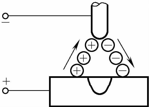 | 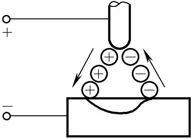 | 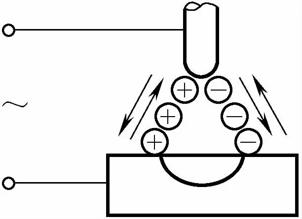 |
| Approximate Ratio of Heat Distribution | Workpiece 70%, Electrode 30% | Workpiece 30%, Electrode 70% | Workpiece 50%, Electrode 50% |
| Characteristics of Penetration | Deep and narrow | Shallow and wide | Medium |
| athodic Cleaning Action | None | Present | Present (when the workpiece is negative) |
| ф3.2W Electrode Allowed Maximum Current | 400A | 420A | 250A |
| Applicable Materials | Brass, copper alloys, cast iron, stainless steel, dissimilar metalen, titanium, silver | Generally not used | Aluminum, magnesium, aluminum bronze, beryllium bronze, cast aluminum |
Welding current is usually selected based on the material, thickness, and position of the weldment. The diameter of the tungsten electrode must be chosen based on the welding current. The allowable welding current range for different tungsten electrode diameters is shown in Table 5-81.
Table 5-81 Allowable welding current range for different tungsten electrode diameters (unit: A)
| Electrode Diameter/mm | Alternating Current | Direct Current, Straight Polarity | Direct Current, Reverse Polarity | |||
| Pure Tungsten | Thoriated Tungsten, Ceriated Tungsten | Tungsten | Thoriated Tungsten, Ceriated Tungsten | Tungsten | Thoriated Tungsten, Ceriated Tungsten | |
| 0.5 | 2~15 | 2~15 | 2~20 | 2~20 | - | - |
| 1 | 15~55 | 15~70 | 10~75 | 10~75 | - | - |
| 1.6 | 45~90 | 60~125 | 40 ~130 | 60~150 | 10~20 | 10 ~20 |
| 2 | 65~125 | 85~160 | 75~180 | 100~200 | 15~25 | 15~25 |
| 2.5 | 80~140 | 120~210 | 130~230 | 170~250 | 17~30 | 17~30 |
| 3.2 | 140 ~190 | 150~250 | 160 ~310 | 225~330 | 20~35 | 20~35 |
| 4 | 180~260 | 240~350 | 275~450 | 350~480 | 35~50 | 35~50 |
| 5 | 240~350 | 330~460 | 400~625 | 500 ~ 675 | 50~70 | 50 ~70 |
| 6.3 | 300~450 | 430~575 | 550~675 | 650~950 | 60~100 | 65~100 |
Arc voltage is the main parameter determining the width of the weld bead. Lower arc voltages are used in TIG welding to achieve good molten pool protection. When welding under helium protection, due to the higher ionization of helium, the same arc length has a higher arc voltage compared to an argon arc.
The arc voltage is related to the angle of the tungsten electrode tip. The sharper the tip of the tungsten electrode, the higher the arc voltage, with a common range of 10~20V.
The choice of tungsten electrode diameter depends on the type, polarity, and size of the welding current to be used. At the same time, the sharpness of the tungsten electrode tip affects the depth and width of the weld. See Table 5-82 for tungsten electrode tip shapes and current ranges.
Table 5-82 Tungsten electrode tip shapes and current ranges
| Tungsten Electrode Diameter /mm | Tip Diameter /mm | Tip Angle / (°) | Direct Current Electrode Positive | |
| Constant DC Current /A | Pulse Current /A | |||
| 1 | 0.125 | 12 | 2~15 | 2~25 |
| 1 | 0.25 | 20 | 5~30 | 5~60 |
| 1.6 | 0.5 | 25 | 8~50 | 8~100 |
| 1.6 | 0.8 | 30 | 10~70 | 10~140 |
| 2.4 | 0.8 | 35 | 12~90 | 12~180 |
| 2.4 | 1.1 | 45 | 15 ~150 | 15~250 |
| 3.2 | 1.1 | 60 | 20~200 | 20~300 |
| 3.2 | 1.5 | 90 | 25~250 | 25~350 |
The welding speed of TIG welding depends on the thickness of the workpiece and the welding current. Since the tungsten electrode can withstand lower currents, the welding speed is usually below 20m/h. The maximum welding speed of mechanized TIG welding can exceed 35m/h, but at this time, the effect of welding speed on the laminar shape of the shielding gas must be considered.
The minimum gas flow required to effectively protect the welding area is related to the shape and size of the welding torch nozzle. The nozzle diameter depends on the thickness of the workpiece and the type of joint, and as the nozzle diameter increases, the gas flow needs to be correspondingly increased.
The nozzle diameter can be selected according to the following formula:
D=(2.5 ~3.5)d w
In de formule:
Once the nozzle diameter is determined, the argon flow rate can be calculated as follows:
Q=(0.8 ~1.2)D
Waar:
When D is small, take the lower limit for Q; when D is large, take the upper limit for Q.
Generally, when the nozzle aperture is 8~12mm, the protective gas flow rate is 5~15L/min; when the nozzle diameter increases to 14~22mm, the gas flow rate is 10~20L/min. When welding thick plates of aluminum and aluminum alloys, the gas flow rate should reach 25~35L/min.
Additionally, the gas flow rate also depends on the welding environment. When welding in an area with air movement, the gas flow rate should be increased according to the air velocity, and the flow rate can also be selected through trial welding. When the flow rate is appropriate, the color of the weld surface can be used to identify.
The relationship between the color and protective effect of stainless steel welds is shown in Table 5-83.
Table 5-83 Relationship between the color and protective effect of stainless steel welds
| Weld Seam Colors | Silver-white, golden-yellow | Blue | Red-gray | Gray | Black |
| Protection Effectiveness | Excellent | Good | Fair | Poor | Worst |
The relationship between the color and protective effect of titanium and titanium alloy welds is shown in Table 5-84.
Table 5-84 Relationship between the color of titanium and titanium alloy welds and protection effect
| Weld Seam Colors | Silver-White | Gold | Purple-Blue | Blue-Gray | Yellow-White |
| Protection Effectiveness | Excellent | Good | Fair | Poor | Worst |
See Table 5-85 for argon flow rate, nozzle aperture, and distance to the workpiece.
Table 5-85 Argon flow rate, nozzle aperture, and distance to the workpiece
| Welding Methods | Appropriate Argon Flow Rate (L/min) | Nozzle Diameter (mm) | Distance Between Nozzle and Workpiece (mm) |
| Tungsten Inert Gas Welding (TIG) | 3~25 | 5 ~20 | 5 ~12 |
| Metal Inert Gas Welding (MIG) | 10~50 | ≤30 | 8~15 |
See Table 5-86 for the relationship between welding current, nozzle diameter, and gas flow rate.
Table 5-86 Relationship between welding current, nozzle diameter, and gas flow rate
| Welding Current /A | DC Welding | AC Welding | ||
| Nozzle Diameter /mm | Gas Flow Rate / (L/min) | Nozzle Diameter /mm | Gas Flow Rate / (L/min) | |
| 10 ~100 | 4~9.5 | 4 ~5 | 8~9.5 | 6~8 |
| 101 ~150 | 4 ~9.5 | 4~7 | 9.5~11 | 7 ~10 |
| 151~200 | 6~13 | 6~8 | 11 ~13 | 7 ~10 |
| 201~300 | 8~13 | 8~9 | 13 ~ 16 | 8 ~15 |
| 301~500 | 13 ~16 | 9~12 | 16 ~19 | 8~15 |
Note: The maximum allowable welding current for metal nozzles is 500A, and for ceramic nozzles, it is 300A.
Automatic TIG welding parameters include manual tungsten electrode argon arc welding parameters and wire feed speed. The wire feed speed should match the welding speed and welding current. The impact of TIG welding parameters on weld formation and welding quality is rarely independent in actual production, such as in manual TIG welding processes, only welding current and argon flow rate are specified.
During automatic TIG welding, the welding parameters that need to be controlled include welding current, arc voltage, welding speed, argon flow rate, wire diameter, and wire feed speed. In addition, when welding particularly reactive metals such as titanium, enhanced protection of the high-temperature zone is necessary, and strict protective measures must be taken.
Table 5-87 Manual TIG Welding Parameters for Aluminum and Aluminum Alloys, Stainless Steel
| Materiaal | Plaatdikte/mm | Groove Type | Number of Weld Layers (Front/Back) | Tungsten Electrode Diameter/mm | Welding Wire Diameter/mm | Preheat Temperature/°C | Welding Current/A | Argon Flow Rate/(L/min) | Nozzle Aperture/mm |
| Aluminium en aluminiumlegeringen | 1 | Beveled Edge | Front 1 | 2 | 1.6 | - | 45 ~ 60 | 7~9 | 8 |
| 1.5 | Beveled or I-groove | Front 1 | 2 | 1.6~2.0 | - | 50~80 | 7~9 | 8 | |
| 2 | I-groove | Front 1 | 2 ~3 | 2~2.5 | - | 90 ~120 | 8 ~12 | 8~12 | |
| 3 | Y-groove | Front 1 | 3 | 2~3 | - | 150 ~180 | 8~12 | 8~12 | |
| 4 | 1~2/1 | 4 | 3 | - | 180 ~200 | 10~15 | 8~12 | ||
| 5 | 1~2/1 | 4 | 3~4 | - | 180~240 | 10~15 | 10 ~12 | ||
| 6 | 1~2/1 | 5 | 4 | - | 240~280 | 16~20 | 14 ~16 | ||
| 8 | 2 /1 | 5 | 4~5 | 100 | 260~320 | 16~20 | 14 ~16 | ||
| 10 | 3~4/1~2 | 5 | 4~5 | 100 ~150 | 280~340 | 16~20 | 14 ~16 | ||
| 12 | 3~4/1~2 | 5 ~6 | 4~5 | 150~200 | 300~360 | 18~22 | 16~20 | ||
| 14 | 3 ~4/1~2 | 5 ~6 | 5~6 | 180~200 | 340~380 | 20~24 | 16 ~20 | ||
| 16 | 4~5/1~2 | 6 | 5~6 | 200 ~220 | 340~380 | 20~24 | 16~20 | ||
| 18 | 4~5/1~2 | 6 | 5~6 | 200~240 | 360~400 | 25~30 | 16~20 | ||
| 20 | 4~5/1~2 | 6 | 5~6 | 200~260 | 360~400 | 25~30 | 20~22 | ||
| 16 ~20 | X-groove | 2~3/2~3 | 6 | 5~6 | 200~260 | 300~380 | 25~30 | 16~20 | |
| 22~25 | 3 ~4/3 ~4 | 6 ~7 | 5~6 | 200~260 | 360~400 | 30~35 | 20~22 | ||
| Stainless Steel | 1 | Butt Joint | 1 | 2 | 1.6 | - | 7~28 | 3~4 | 12~47① |
| 1.2 | Butt Joint | 1 | 2 | 1.6 | - | 15 | 3~4 | 25① | |
| 1.5 | Butt Joint | 1 | 2 | 1.6 | - | 5 ~19 | 3~4 | 8~32① |
① Welding speed, in cm/min.
Table 5-88 Manual TIG Welding Parameters for Carbon Steel, Low Alloy Steel
| Weldment Thickness/mm | Welding Current/A | Wire Diameter/mm | Welding Speed/(mm/min) | Gas Flow Rate/(L/min) |
| 0.9 | 100 | ф1.6 | 300~370 | 4~5 |
| 1.2 | 100~125 | ф1.6 | 300~450 | 4~5 |
| 1.5 | 100 ~140 | ф1.6 | 300~450 | 4~5 |
| 2.5 | 140~180 | ф2 | 300 ~450 | 5~6 |
| 3.2 | 150 ~200 | ф3 | 250~300 | 5~6 |
Table 5-89 Manual TIG Welding Parameters for Copper and Copper Alloys
| Materiaal | Weld Thickness/mm | Groove Type | Tungsten Electrode | Electrode Diameter/mm | Filler Wire Diameter/mm | Welding Current/A | Nozzle Diameter/mm | Gas Flow Rate/(L/min) | Preheat Temperature/°C |
|---|---|---|---|---|---|---|---|---|---|
| Copper | <1.5 | Single-V | Thoriated | 2.4 | 2 | 140-180 | 8 | 6-8 | - |
| 2-3 | Single-V | Thoriated | 3.2 | 3 | 160-280 | 8-10 | 6-10 | - | |
| 4-5 | V-groove | Thoriated | 4 | 3-4 | 250-350 | 10-12 | 8-12 | 100-150 | |
| 6-10 | V-groove | Thoriated | 5 | 4-5 | 300-400 | 10-12 | 10-14 | 300-500 | |
| Messing | 1.2 | Butt joint | Thoriated | 3.2 | - | 160-180 | 8 | 7 | - |
| Tin Brass | 2 | Single-V | Thoriated | 3.2 | 3 | 180-200 | 8 | 7 | - |
| Tin Phosphorus | <1.6 | Single-V | Thoriated | 3.2 | 1.6 | 90-150 | 10-12 | 8-12 | - |
| Bronze | 1.6-3.2 | Single-V | Thoriated | 3.2 | 2-3 | 100-220 | 10-12 | 8-12 | - |
| Aluminum Bronze | <1.6 | Single-V | Ceriated | 1.6 | 1.6 | 25-80 | 10-12 | 9-10 | - |
| 3.2 | Single-V | Ceriated | 3.2 | 2-3 | 160-210 | 10-12 | 10-12 | - | |
| 9.5 | V-groove | Ceriated | 4 | 4 | 210-330 | 10-12 | 12-13 | - | |
| Silicon Bronze | 1.6 | Single-V | Ceriated | 1.6 | 1.6 | 100-120 | 8 | 7 | - |
| 3.2 | Single-V | Thoriated | 2.4 | 2 | 130-150 | 8 | 7 | - | |
| 6.4 | V-groove | Thoriated | 3.2 | 3 | 200-250 | 10 | 9 | - | |
| 9.5 | V-groove | Thoriated | 3.2 | 3 | 230-280 | 10 | 9 | - | |
| Nickel Bronze | <3.2 | Single-V | Thoriated | 3.2 | 2-3 | 250-300 | 12-14 | 12-14 | - |
| 3.2-9.5 | V-groove | Thoriated | 4 | 3 | 280-320 | 12-14 | 12-14 | - |
Table 5-90 Titanium and titanium alloy manual TIG welding (DC positive connection, butt joint) welding parameters
| Plaatdikte/mm | Bevel Type | Number of Weld Layers | Tungsten Electrode Diameter/mm | Wire Diameter/mm | Welding Current/A | Argon Flow Rate/(L/min) | Nozzle Diameter/mm | Opmerkingen | ||
| Main Nozzle | Drag Shield | Back Side | ||||||||
| 0.5 | Single-V Bevel | 1 | 1.5 | 1.0 | 30 ~50 | 8~10 | 14~16 | 6~8 | 10 | Butt joint gap 0.5mm, titanium may also not be added Wire gap 1.0mm |
| 1 | 1 | 2.0 | 1.0~2.0 | 40~60 | 8~10 | 14~16 | 6~8 | 10 | ||
| 1.5 | 1 | 2.0 | 1.0~2.0 | 60~80 | 10~12 | 14~16 | 8~10 | 10 ~12 | ||
| 2 | 1 | 2.0~3.0 | 1.0~2.0 | 80~110 | 12~14 | 16~20 | 10~12 | 12 ~14 | ||
| 2.5 | 1 | 2.0~3.0 | 2.0 | 110~120 | 12~14 | 16~20 | 10~12 | 12 ~14 | ||
| 3 | Single-Y Bevel | 1 ~2 | 3.0 | 2.0~3.0 | 120~140 | 12~14 | 16~20 | 10~12 | 14 ~18 | Bevel gap 2~3mm, blunt edge 0.5mm The back of the weld is lined with a steel backing plate Bevel angle 60°~65° |
| 3.5 | 1~2 | 3.0~4.0 | 2.0~3.0 | 120~140 | 12~14 | 16~20 | 10~12 | 14 ~18 | ||
| 4 | 2 | 3.0~4.0 | 2.0~3.0 | 130~150 | 14~16 | 20~25 | 12~14 | 18 ~20 | ||
| 4 | 2 | 3.0~4.0 | 2.0~3.0 | 200 | 14~16 | 20~25 | 12~14 | 18 ~20 | ||
| 5 | 2~3 | 4.0 | 3.0 | 130~150 | 14~16 | 20~25 | 12~14 | 18~20 | ||
| 6 | 2~3 | 4.0 | 3.0~4.0 | 140~180 | 14~16 | 25~28 | 12~14 | 18~20 | ||
| 7 | 2~3 | 4.0 | 3.0~4.0 | 140~180 | 14~16 | 25~28 | 12~14 | 20~22 | ||
| 8 | 3 ~4 | 4.0 | 3.0~4.0 | 140~180 | 14~16 | 25~28 | 12~14 | 20~22 | ||
| 10 | Double-Y Bevel | 4~6 | 4.0 | 3.0~4.0 | 160~200 | 14~16 | 25~28 | 12~14 | 20~22 | Bevel angle 60°, blunt edge 1mm Bevel angle 55°, blunt edge 1.5-2.0mm Bevel angle 55°, blunt edge 1.5~2.0mm, gap 1.5mm |
| 13 | 6~8 | 4.0 | 3.0~4.0 | 220~240 | 14~16 | 25~28 | 12~14 | 20~22 | ||
| 20 | 12 | 4.0 | 4.0 | 200~240 | 12~14 | 20 | 10~12 | 18 | ||
| 22 | 6 | 4.0 | 4.0~5.0 | 230~250 | 15~18 | 18~20 | 18~20 | 20 | ||
| 25 | 15~16 | 4.0 | 3.0~4.0 | 200~220 | 16~18 | 26~30 | 20~26 | 22 | ||
| 30 | 17~18 | 4.0 | 3.0~4.0 | 200~220 | 16~18 | 26~30 | 20~26 | 22 | ||
Table 5-91 Automated TIG welding parameters for aluminum and aluminum alloys
| Materiaal | Plaatdikte/mm | Number of Weld Layers | Tungsten Electrode Diameter/mm | Wire Diameter/mm | Welding Current/A | Argon Flow Rate/(L/min) | Nozzle Aperture/mm | Wire Feed Speed/(cm/min) |
| Aluminium en aluminiumlegeringen | 1 | 1 | 1.5 ~2 | 1.6 | 120 ~160 | 5~6 | 8~10 | - |
| 2 | 1 | 3 | 1.6~2 | 180 ~220 | 12 ~14 | 8 ~10 | 108 ~117 | |
| 3 | 1~2 | 4 | 2 | 220~240 | 14 ~18 | 10 ~14 | 108~117 | |
| 4 | 1~2 | 5 | 2~3 | 240~280 | 14 ~18 | 10 ~14 | 117 ~ 125 | |
| 5 | 2 | 5 | 2~3 | 280 ~320 | 16 ~ 20 | 12 ~16 | 117 ~ 125 | |
| 6~8 | 2~3 | 5~6 | 3 | 280 ~320 | 18~24 | 14 ~18 | 125~133 | |
| 8~12 | 2~3 | 6 | 3~4 | 300 ~340 | 18~24 | 14 ~18 | 133 ~142 | |
| Stainless steel | 1.5 | 1 | 2 | 1.6 | 125 ~130 | 8~10 | 260 | |
| 2 | 1 | 3 | 1.6 | 138~142 | 6~8 | 260 |
Table 5-92 Automated TIG welding parameters for titanium and titanium alloys (DC positive, butt joint)
| Plate Thickness / mm | Bevel Type | Number of Welding Layers | Dimensions of the Backing Strip in the Forming Groove | Tungsten Electrode Diameter / mm | Wire Diameter / mm | Welding Current / A | Arc Voltage / V | Welding Speed / (cm/min) | Argon Flow Rate / (L/min) | |||
| Width / mm | Depth / mm | Main Nozzle | Trailing Shield | Back Side | ||||||||
| 1 | I-grove | 1 | 5 | 0.5 | 1.6 | 1.2 | 70~100 | 12~15 | 30~37 | 8~10 | 12~14 | 6~8 |
| 1.2 | I-grove | 1 | 5 | 0.7 | 2 | 1.2 | 100~120 | 12~15 | 30~37 | 8~10 | 12~14 | 6~8 |
| 1.5 | I-grove | 1 | 5 | 0.7 | 2 | 1.2~1.6 | 120~140 | 14~16 | 37~40 | 10~12 | 14~16 | 8~10 |
| 2 | I-grove | 1 | 6 | 1 | 2.5 | 1.6~2.0 | 140~160 | 14~16 | 33~37 | 12~14 | 14~16 | 10~12 |
| 3 | I-grove | 1 | 7 | 1.1 | 3 | 2.0~3.0 | 200~240 | 14~16 | 32~35 | 12~14 | 16~18 | 10~12 |
| 4 | Single Bevel with 2mm Gap | 2 | 8 | 1.3 | 2 | 3 | 200~260 | 14~16 | 32~33 | 14~16 | 18~20 | 12~14 |
| 6 | Y-Groove 60° | 3 | - | - | 4 | 3 | 240~280 | 14~18 | 30~37 | 14~16 | 20~24 | 14~16 |
| 10 | Y-Groove 60° | 3 | - | - | 4 | 3 | 200~260 | 14~18 | 15~20 | 14~16 | 18~20 | 12~14 |
| 13 | Double Y-Groove 60° | 4 | - | - | 4 | 3 | 220~260 | 14~18 | 33~42 | 14~16 | 18~20 | 12~14 |
Table 5-93 TIG welding parameters for austenitic stainless steel pipes (suspended welding)
| Thickness/mm | Bevel Shape | Welding Current/A | Welding Speed/(mm/min) | Opmerkingen |
| 1.5 | 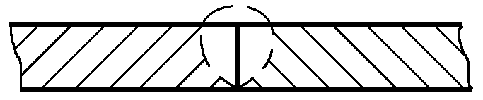 | 100 ~110 | 460 ~480 | Used for overhead welding of round and square tubes, with argon gas protection inside the tube to shield the back of the weld. |
| 2 | 120 ~130 | 400 ~410 | ||
| 3 | 190~200 | 300 ~310 |
Table 5-94 Welding parameters for the root pass of multi-layer TIG welding of stainless steel thick-walled pipes
| Wire Diameter / mm | Tungsten Electrode Diameter / mm | Current Polarity | Welding Current / A | Arc Voltage / V | Welding Speed / (cm/min) | Weaving Method | Shielding Gas | |
| Types | Flow Rate / (L/min) | |||||||
| 2.0(1.6) | 1.6 | Direct current | 50~130 | 9~16 | 4~14 | Transverse Oscillation | Argon purity (volume fraction) greater than 99.9% | 8~15 |
| 2.4 | 2.4 | Tangent | ||||||