Oppervlaktekwaliteit verbeteren bij machinale bewerking: Sleuteltechnieken
De oppervlaktekwaliteit van machinale bewerking verwijst naar de oppervlaktegesteldheid van het onderdeel na machinale bewerking. De...
Fusion welding is a method of welding in which the base metal at the welding point is melted (often with the addition of filler metal) without applying pressure, forming a weld seam.
The essence of fusion welding is a small-scale melting and casting process, involving the melting and crystallization of metal. When the temperature reaches the melting point of the material, the base metal and welding wire melt to form a molten pool, which crystallizes into columnar crystals. The molten pool exists for a short time, has a high temperature, cools quickly, and easily forms coarse columnar crystals after crystallization.
To achieve a good welding joint, an appropriate heat source, good molten pool protection, and weld seam filler metal are necessary. These are known as the three essentials of fusion welding.
The energy should be concentrated and the temperature high to ensure rapid metal melting and minimize the heat-affected zone. Suitable heat sources include arc, plasma arc, electric slag heat, electron beam, and laser, among others.
Slag protection, gas protection, and a combination of slag-gas protection can be used to prevent oxidation and carry out deoxygenation, desulfurization, and dephosphorization, transitioning alloy elements to the weld seam.
This ensures the weld seam is filled and beneficial alloy elements are introduced, achieving the required mechanical properties and other performance requirements. The main types are welding core and welding wire.
Common fusion welding methods include gas welding, stick arc welding, booglassen onder poederdek, argon arc welding, CO2 gas shielded welding, electric slag welding, plasma arc welding, electron beam welding, and laser welding, among others.
Submerged arc welding is a method where the welding wire is automatically and continuously fed, and the arc burns beneath a layer of flux for welding. The granular flux replaces the coating of welding rods, and the automatically fed welding wire replaces the core of the rods. As the processes of arc striking, wire feeding, and arc advancement are all carried out by machines, it results in high productivity and welding quality.
As shown in Figure 4-18, the principle of submerged arc welding involves covering the welding joint with a layer of granular flux approximately 30-50mm thick. The automatic welding head feeds the continuous coil-shaped welding wire into the arc zone, maintaining a certain arc length. It melts the welding wire, the joint of the workpiece, and some of the flux, which forms slag and a molten pool, leading to metallurgical reactions.
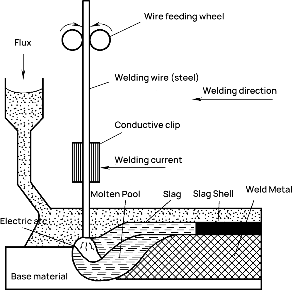
Some flux and metal evaporate to form gases. The gas with a certain pressure pushes aside the slag surrounding the arc, forming a closed slag bubble. It has a certain viscosity and can withstand a certain pressure. The molten pool metal, enclosed by the slag bubble, is isolated from the air, preventing metal spatter, reducing heat loss, and preventing arc light from scattering.
As the automatic welding machine moves forward (or the machine stays stationary while the workpiece moves at a uniform speed), the parent metal and welding wire beneath the arc are continuously heated and melted, forming a common molten pool. The metal behind the pool cools and solidifies into a weld seam. The slag floating on the pool surface condenses into welding slag, and the unmelted flux can be recycled and reused after recovery.
1) Preparation before welding.
Submerged arc welding involves a large welding current and deep fusion, so workpieces with a thickness of 20-25mm or less do not need a groove. However, in actual production, to ensure full penetration of the workpiece, a Y-shaped groove should be cut when the plate thickness is 14-22mm. When the plate thickness is 22-50mm, a double Y-shaped or U-shaped groove can be cut.
The angle for Y-shaped and double Y-shaped grooves is 50-60 degrees. The weld seam gap should be uniform. When welding a straight seam, a starting board and an outgoing board (Figure 4-19f) should be installed to prevent defects such as pores, inclusions, shrinkage cavities, and looseness caused by arc striking and extinction from entering the weld seam of the workpiece, affecting the welding quality.
2) Flat plate butt welding.
As shown in Figure 4-19, when butt welding flat plates, double-sided welding is generally adopted. You can weld both sides without leaving a gap directly, or you can choose to perform root welding or pad welding. To improve productivity, water-cooled copper plates can be used for single-sided welding with double-sided formation.
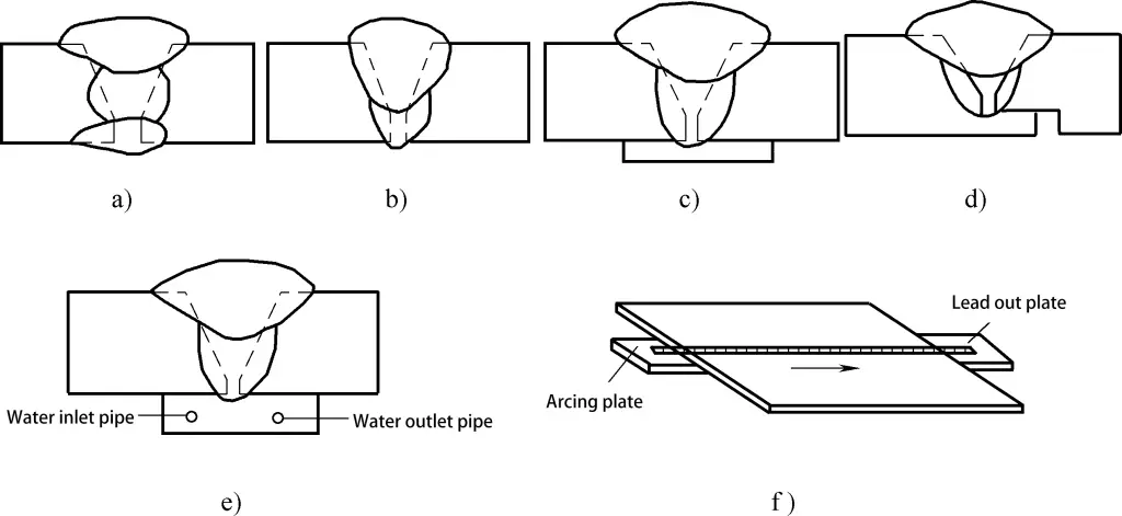
a) Double-sided welding
b) Tack welding
c) Using a backing plate
d) Using a back-gouged groove
e) Water-cooled copper plate
f) Using a strike plate and a run-off plate
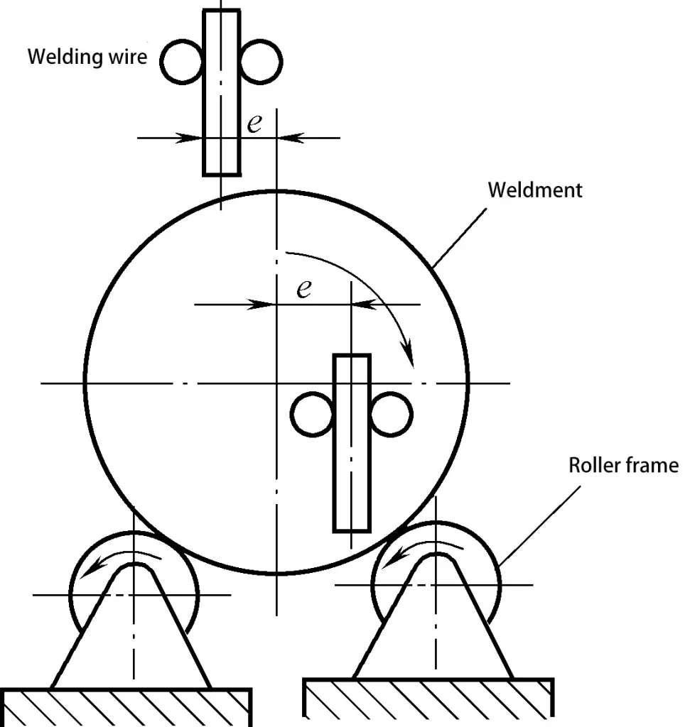
3) Circular weld seams.
When welding circular weld seams, the starting point of the welding wire should be a certain distance ‘e’ away from the centerline of the circle (Figure 4-20) to prevent the molten pool metal from flowing. Generally, e=20-40mm. Circular weld seams of components with a diameter less than 250mm are generally not welded with the submerged arc welding method.
Compared to shielded metal arc welding, submerged arc welding has the following advantages:
1) High productivity.
The current in submerged arc welding often exceeds 1000A, 6-8 times higher than shielded metal arc welding. Therefore, it has a larger molten depth and higher welding speed. There is no need to change the welding wire, saving time, and the productivity is 5-10 times higher than shielded metal arc welding.
2) High and stable welding quality.
The welding process is automatic, and the process parameters are stable. The molten pool remains liquid for a longer time, making the metallurgical process more thorough. Gases and slag are easy to float out, and the chemical composition of the weld metal is uniform. At the same time, due to the ample flux, the arc zone is well protected, resulting in beautiful weld formation and stable welding quality.
3) Saves metal materials and has low production costs.
The workpiece for submerged arc welding may not need or need fewer grooves, saving metal materials and welding materials consumed due to grooving. Also, there is no loss of lasstaaf ends as in shielded metal arc welding, and less spatter of molten droplets, hence lower production costs.
4) Good working conditions.
The mechanization and automation of the submerged arc welding process significantly reduce the labor intensity of workers. Moreover, since the arc is buried under the flux, the arc light is not visible, and there is less welding smoke, improving the working conditions.
Submerged arc welding is only suitable for flat welding, long straight seams, and large-diameter circular seam welding. It is not suitable for thin plates and curved seam welding. Moreover, it has higher pre-assembly requirements for the workpiece.
Submerged arc welding is applicable to carbon steel, low-alloy structural steel, stainless steel, heat-resistant steel, etc. It is mainly used in circumferential seam welding and straight seam welding of pressure vessels, long straight seam welding of boiler cooling walls, ship and submarine hulls, cranes, metallurgical machinery (blast furnace body), and so on.
Argon arc welding is an arc welding method that uses argon gas to protect the arc and the welding area. As an inert gas, argon does not dissolve in liquid metal and does not react with metal.
Once the argon arc is ignited, the arc is very stable. Depending on the type of electrode used, argon arc welding is divided into two types: consumable electrode argon arc welding and non-consumable electrode argon arc welding (also known as tungsten electrode argon arc welding).
1) Consumable Electrode Argon Arc Welding.
This type of welding uses a continuously fed wire as the electrode, which, after melting, also serves as the filler metal in inert gas shielded welding, commonly known as MIG welding, as shown in Figure 4-21a.
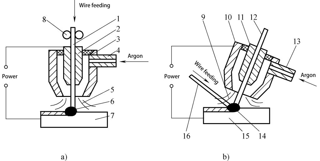
1,16—Welding Wire
2,11—Conductive Nozzle
3,10—Nozzle
4,13—Air Intake Pipe
5, 9—Gas Flow
6,14—Electric Arc
7,15—Workpiece
8—Wire Feed Wheel
12—Tungsten Rod
The wire droplets typically enter the weld pool through a fine “spray transition.” The current used in welding is relatively high, the productivity is high, and it is suitable for welding medium and thick plates below 25mm. When welding aluminum and its alloys, direct current reverse polarity (workpiece connected to the negative electrode) is often used to improve the stability of the arc.
At the same time, the large mass argon ions are used to bombard the surface of the molten pool, breaking the high melting point oxide film that is easily formed on the surface of the molten pool, which is beneficial to the fusion of the weld and ensuring the quality of welding. This effect is known as “cathode cleaning” (also called “cathode atomization”).
Because the welding wire serves as both the electrode and the filler material, a dedicated wire feeding mechanism is required.
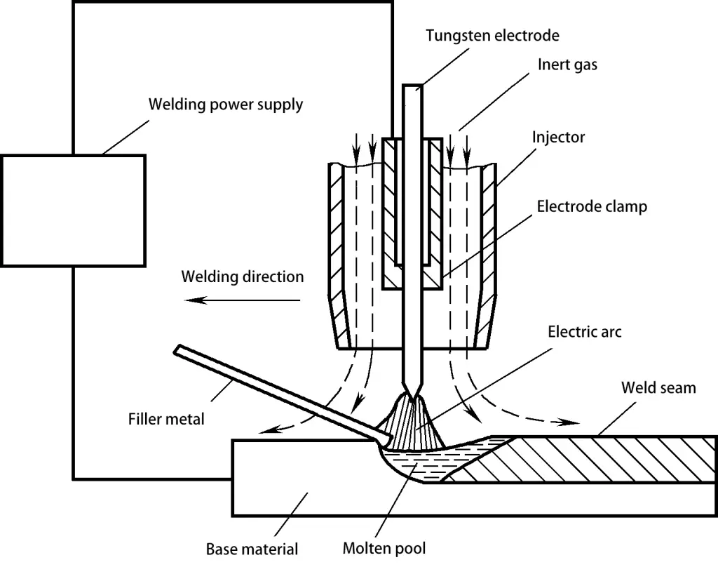
2) Non-consumable Electrode Argon Arc Welding.
This type of welding uses a pure tungsten or tungsten alloy rod with a high melting point as the electrode in inert gas shielded welding, commonly known as TIG welding. During welding, the tungsten electrode does not melt and only serves as an electrode for electrical conduction. The welding wire is fed into the weld pool from the front of the tungsten electrode (Figure 4-21b).
When welding steel parts, direct current electrode positive (workpiece connected to the positive electrode) is often used, otherwise the tungsten electrode is easily burnt. When welding colored metalen such as aluminum, magnesium and their alloys, direct current reverse polarity or alternating current argon arc welding can be used.
When the workpiece is at the negative electrode or during the negative half cycle of the alternating power source, the “cathode cleaning” effect can be utilized. In order to reduce the burnout of the tungsten electrode, the welding current passing through the electrode should not be too large, and the depth of the weld is shallow, so non-consumable electrode argon arc welding is usually used for welding thin plates with a thickness of less than 6mm.
1) Superior welding quality.
The inert gas provides effective shielding, resulting in pure and aesthetically pleasing weld seams.
2) Minimal heat-affected zone and deformation.
The argon arc welding process features a stable and concentrated energy arc (due to the constriction of the arc), which makes the welding process easy to control.
3) Facilitates mechanization and automation.
With open arc welding, the weld seam formation is easy to observe; post-weld slag removal is not required.
Argon arc welding does have some drawbacks: argon gas is expensive, the equipment cost is high, stringent pre-weld cleaning is required, and argon gas does not have deoxygenation and dehydrogenation effects. Argon arc welding is suitable for welding easily oxidizable non-ferrous metals, alloy steels, and other materials, such as aluminum, magnesium, titanium and their alloys, heat-resistant steels, stainless steels, and more.
CO2 gas shielded welding, commonly referred to as CO2 welding, is a type of metal inert gas (MIG) welding that uses CO2 gas to shield the arc and the welding area. This welding method uses continuously fed welding wire as the electrode, relying on the arc generated between the wire and the workpiece to melt the base metal and the wire, enabling automatic or semi-automatic welding.
Once the arc is ignited, the end of the welding wire, the arc, and the molten pool are surrounded by CO2 gas, which protects the high-temperature metal from the harmful effects of air. Its principle and equipment are similar to those of metal inert gas (MIG) welding, with the difference being the shielding gas used. The commonly used welding wire is H08Mn2SiA.
Characteristics of CO2 Gas Shielded Welding:
1) High productivity. With automatic wire feeding, high current density, and concentrated arc heat, the welding speed is high. There is no slag after welding, saving slag removal time. The productivity is 1 to 4 times higher than that of stick arc welding.
2) Good welding quality. Due to the protection of CO2 gas, the weld seam has a low hydrogen content, and the wire has a high manganese content, resulting in a significant desulfurization effect. Furthermore, as the arc burns under compressed gas flow, the heat is concentrated, the heat-affected zone is small, and the welded joint has good crack resistance.
3) Good operational performance. CO2 gas shielded welding is an open arc welding process, making it easy to identify welding problems and address them promptly. It’s also suitable for welding in various positions, offering flexible operation.
4) Low cost. CO2 gas is inexpensive, and the welding wire is a disc-shaped bare wire, making the cost only about 40% of that of submerged arc welding and stick arc welding.
CO2 gas shielded welding also has its drawbacks, such as significant spattering, poor weld formation, and a tendency to create gas pockets. Furthermore, metals and alloy elements are prone to oxidation and burn-off, making it unsuitable for welding easily oxidizable non-ferrous metals and high-alloy steels.
CO2 gas shielded welding is suitable for welding low carbon steel and general low-alloy structural steel with not high strength levels, primarily used for thin plate welding.
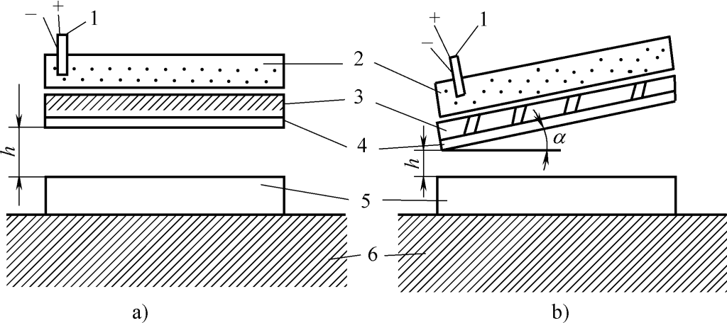
Electroslag welding is a fusion welding method that uses the resistive heat generated when electric current passes through liquid slag.
The welding process of electroslag welding is shown in Figure 4-22. The two workpieces are placed vertically (in a vertical weld seam), spaced 20-60mm apart, with water-cooled copper sliders on both sides, an arc starter plate at the bottom, and a lead-out plate at the top. At the start of welding, the welding wire short-circuits with the arc starter plate to initiate the arc.
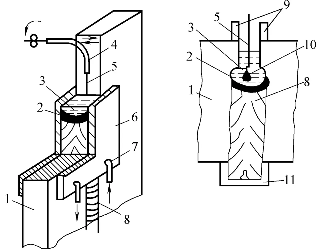
1—Workpiece
2—Metal Melt Pool
3—Slag Pool
4—Conductive Nozzle
5—Welding Wire
6—Slider
7—Cooling Water Tube
8—Weld Seam
9—Lead-out Plate
10—Melted Welding Wire
11—Arc Initiating Plate
The arc melts the continuously added flux to form a slag pool. When the slag pool reaches a certain thickness, the arc extinguishes, and the welding wire and workpiece are melted by the resistive heat of the slag pool.
As the amount of filler metal increases, the slag pool gradually rises, and the water-cooled sliders on both sides rise along with it. The lower part of the weld seam solidifies successively, forming a weld seam. Depending on the thickness of the workpiece, single or multiple wires can be used.
Features of Electroslag Welding:
1) High productivity. Large workpieces can be welded in one operation. For example, if a single wire does not swing, it can weld thicknesses of 40-60mm; if a single wire swings, it can weld thicknesses of 60-150mm.
2) Good welding quality. The weld seam’s liquid metal has a long dwell time, making it less likely to produce gas pockets, inclusions, and other defects; the slag covers the weld pool and provides good protection.
3) High productivity and low cost. There is no need to groove for any thickness, just leave a gap of 25-60mm, and it can be welded in one operation; welding materials and electrical energy consumption are low.
The drawback of electroslag welding is that the weld pool stays at a high temperature for a long time, the grains are coarse, the heat affected zone is wide, and post-weld annealing is required; the welding adaptability is poor; it is always done in the vertical welding manner, can’t be done flat, is not suitable for welding thin workpieces, and the weld seam should not be too long.
Electroslag welding is suitable for welding materials such as carbon steel, alloy steel, and stainless steel. It is mainly used for welding thick-walled pressure vessels, cast-welding, forge-welding, and large components such as thick plate splicing welding. The welding thickness should generally be greater than 40mm.
Plasma arc welding is a welding process that compresses an arc into a narrow plasma beam through mechanical compression effects (forced contraction when the arc passes through the small hole of the nozzle), thermal compression effects (under the strong action of cold airflow, charged particles, negative ions, and electron flow concentrate towards the center of the arc column), and electromagnetic contraction effects (the current lines of the charged particles in the arc column are parallel, and the magnetic field causes the current lines to attract each other and contract).
The principle is shown in Figure 4-23. The temperature of the plasma arc reaches 24,000 to 50,000K, with highly concentrated energy and an energy density of 105 to 106W/cm2, which can melt thick materials in a single pass. Plasma arc welding can be used for both welding and cutting.
Plasma arc welding has a high energy density, high arc column temperature, strong penetration power, and can weld through 10-12mm steel in a single pass without beveling, with double-sided formation. It has a fast welding speed, high productivity, small heat-affected zone, minimal welding deformation, and good weld quality.
When the current is as low as 0.1A, the plasma arc can still burn stably and can weld ultra-thin plates of 0.1-2mm thickness, such as foils and thermocouples. However, the equipment for plasma arc welding is complex, and it consumes a large amount of gas, making it only suitable for indoor welding.
Currently, plasma arc welding is mainly used in the defense industry and cutting-edge industrial technology for welding difficult-to-melt, easily oxidized, and thermally sensitive materials, such as copper, tungsten, nickel, molybdenum, aluminum, titanium and their alloys, as well as stainless steel and high-strength steel.
Electron beam welding is a fusion welding method that utilizes an accelerated and focused electron beam to generate heat energy by striking workpieces placed in a vacuum or non-vacuum environment.
Depending on the degree of vacuum in the environment where the workpiece is located, electron beam welding is divided into high-vacuum electron beam welding, low-vacuum electron beam welding, and non-vacuum electron beam welding. Figure 4-24 shows the most widely used high-vacuum electron beam welding.
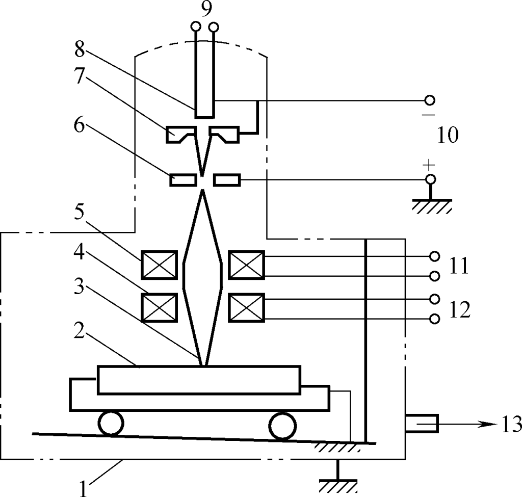
1—Vacuum Chamber
2—Weldment
3—Electron Beam
4—Magnetic Deflection Device
5—Focusing Lens
6—Anode
7—Cathode
8—Filament
9—AC Power Source
10—DC High Voltage Power Source
11, 12— DC Power Source
13—Exhaust Device
In a vacuum, the cathode of the electron gun is electrically heated to a high temperature, emitting a large number of electrons. These electrons are accelerated under the influence of a strong electric field.
The high-speed electrons form a high-energy density (109W/cm2) electron beam through the beam-forming device (anode and focusing lens), striking a very small area of the workpiece at an extremely high speed (1.6×10⁸m/s). The kinetic energy is transformed into heat energy, causing the impacted area to rapidly melt or even vaporize.
The desired joint can be obtained by appropriately moving the workpiece according to its degree of melting. Generally, no filler metal is added in electron beam welding.
Vacuum electron beam welding is performed in a vacuum, so the metal does not oxidize or nitride, resulting in high welding quality. The heat during welding is highly concentrated, resulting in a small heat-affected zone (only 0.05~0.75mm), virtually eliminating welding deformation, making it suitable for welding parts after precision machining.
The adjustable range of electron beam welding process parameters is wide, capable of welding plates of varying thicknesses (0.1~300mm). The energy density of the electron beam is high, the welding speed is fast, and the depth-to-width ratio of the weld can reach 20:1 without the need for a groove, resulting in high productivity and low cost.
Vacuum electron beam welding is suitable for welding various refractory metals (such as titanium, molybdenum, etc.), reactive metals (excluding alloys with a high content of low boiling point elements like tin, zinc, etc.), and various alloy steels, stainless steels, etc.
It can be used for welding thin-walled, microstructures, as well as thick plate structures, such as microelectronic circuit components, large missile casings, thick-walled structures in nuclear equipment, and bearings, gear assemblies, etc.”
Laser welding is a technique that uses the heat produced by a focused laser beam striking the workpiece for welding. A laser is a form of coherent light with high intensity, excellent monochromaticity, and good directionality. The energy density of a focused laser beam is extremely high. In a short period of time, the laser energy can be converted into thermal energy, reaching temperatures of over 10,000°C.
During laser welding (Figure 4-25), the laser is stimulated to produce a laser beam that is focused into a tiny focal point by a focusing system, further concentrating the energy.

When the laser beam is focused on the seam of the workpiece, the light energy is absorbed by the welding material and transformed into thermal energy, generating high temperatures near the focal point, causing the metal to melt instantly and form a welded joint upon cooling.
Laser welding has a high energy density and the heat source acts for a very short time, resulting in a minimal heat-affected zone, minimal welding deformation, and high welding size accuracy. It can be used for welding precision parts and heat-sensitive materials. Meanwhile, due to the extremely fast welding process, the welded material is less likely to oxidize, allowing welding in the atmosphere without the need for vacuum or gas protection.
Laser welding is flexible and can be directed to hard-to-reach areas with the help of deflection prisms or optical fibers, or it can be used to focus weld through transparent materials.
Laser welding is suitable for insulating materials, dissimilar metals, and welding between metals and non-metals. Currently, it is primarily used in micro-precision, densely arranged, and heat-sensitive welding components.
Pressure welding refers to a category of welding methods that achieve non-detachable joints by heating metals to a plastic state, pressurizing them to cause plastic deformation, recrystallization, and atomic diffusion. This brings the atoms of two separate surfaces close enough to form metallic bonds (at a lattice distance of 0.3~0.5nm).
Resistance welding is a method where combined workpieces are pressurized through electrodes, and the heat generated by the resistance when an electric current passes through the contact surface and adjacent area of the welding joint is utilized for welding. Common types include puntlassennaadlassen en stomplassen.
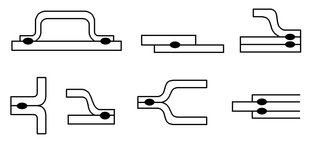
Spot welding is a method of resistance welding that forms a weld spot by locally melting the parent metal through resistance heat. This is achieved by assembling the workpieces into a lap joint, tightly fitting them between two cylindrical electrodes, applying pressure, and passing an electric current. The principle is shown in Figure 4-26, and common forms of spot welding joints are shown in Figure 4-27.
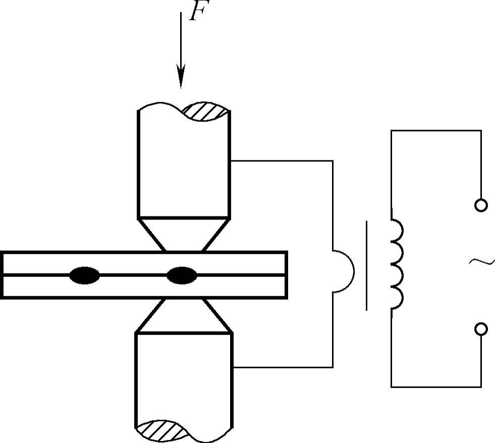
During spot welding, pressure is first applied to ensure the two workpieces are in close contact, followed by heating through an electric current. Because the resistance at the contact point of the workpieces is large, the heat concentrates there, rapidly increasing the temperature and melting the metal to form a melt core of a certain size.
When the current is cut off and the pressure is removed, the melt core at the contact point of the two workpieces solidifies to form a dense weld spot. Before spot welding, it is crucial to strictly clean the oxide film, oil stains, etc., on the surface of the workpieces to avoid affecting the quality of spot welding and the life of the electrodes due to excessive contact resistance of the workpieces.
In addition, during spot welding, some current flows through the already welded spots, reducing the current at the welding spot and causing a shunting phenomenon. To minimize shunting, the spot welding distance should not be too small. The main process parameters affecting the quality of spot welding are electrode pressure, welding current, and energizing time.
If the electrode pressure is too high, the contact resistance decreases, reducing the heat and resulting in insufficient weld spot strength. If the electrode pressure is too low, the contact between the workpieces is poor.
Although the heat source is strong, it is unstable and can even lead to splattering and burn-through defects. If the welding current is insufficient, the heat is insufficient, the melting depth is too small, and it can even cause non-melting; if the current is too high, the melting depth is too large, and there can be metal splattering, even leading to burn-through.
The influence of energizing time on the quality of spot welding is similar to that of current. Spot welding is mainly used for welding thin plate structures below 4mm and reinforcing bars.
Seam welding is a continuous spot welding process. It uses continuously rotating disc-shaped electrodes in place of cylindrical ones, resulting in overlapping continuous weld seams after welding, as shown in Figure 4-28.
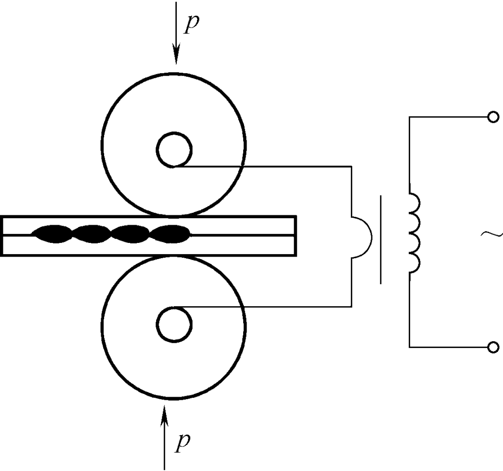
The disc-shaped electrode not only pressurizes and conducts electricity to the workpieces but also moves the workpieces forward through its own rotation to complete the seam welding.
The shunting phenomenon during seam welding is more severe. When welding workpieces of the same thickness, the welding current is 1.5~2 times that of spot welding. Seam welding is commonly used for welding thin-walled containers below 3mm that require sealing, such as oil tanks, water tanks, mufflers, etc.
Butt welding is a method of resistance welding that uses resistive heat to fuse two workpieces together in a butt joint, welding the entire end faces.
1) Resistance Butt Welding: Resistance butt welding involves assembling the workpieces into a butt joint, ensuring their end faces are in close contact, and using resistive heat to heat them to a plastic state. Pressure is then applied to complete the welding. The principle of this welding method is shown in Figure 4-29a. Resistance butt welding has the advantage of smooth joints, minimal burrs, and a simple welding process.
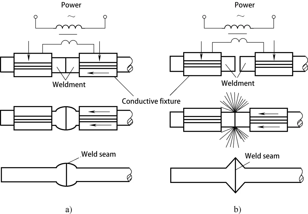
a) Resistance Butt Welding
b) Flash Butt Welding
However, its joints have lower mechanical properties and require high preparation of the workpiece end faces (strict pre-welding cleaning is necessary). It is generally used for butt joints of small cross-section (below 250mm²) metal profiles.
2) Flash Butt Welding: During welding, the workpieces are clamped on the electrode clamp head, the power source is turned on, and they are gradually brought together. Due to the rough contact end faces, only a few points are in contact at the beginning.
When a strong current passes through these few points with a very small contact area, a large amount of resistive heat is generated, causing the metal at the contact points to rapidly melt and even vaporize. The melted metal, under the influence of electromagnetic forces and gas explosion, sprays out with surface oxides, creating a sparkling flash. As the workpieces continue to advance, the flash occurs at the new contact points.
When a thin layer of metal on the entire contact end face of the workpieces has melted, pressure is quickly applied and the power is cut off. The two workpieces then cool and solidify under pressure, welding together. The principle of flash butt welding is shown in Figure 4-29b.
During the flash butt welding process, oxides and impurities on the end of the workpiece are expelled by the flash sparks or squeezed out with the liquid metal, preventing air intrusion. Thus, the joint has fewer impurities, high quality, and both the weld strength and plasticity are higher. The requirement for pre-welding cleaning of the end face is not high.
It is often used for welding important parts such as rail tracks, anchor chains, pipes, wheel rims, and tools. It can also be used for welding different metals (such as aluminum-copper, copper-steel, aluminum-steel, etc.), from metal wires with a diameter of 0.01mm to tubes with a diameter of 500mm, and metal profiles or plates with a cross-section of up to 20000mm².
However, flash butt welding results in more burn-off of the workpieces, and burrs need to be cleaned after welding.”
Resistance welding boasts rapid heating at relatively low temperatures, resulting in minimal thermal impact and deformation of the workpiece, thus facilitating the creation of high-quality joints. It requires no additional filler metal or flux. The process is free of arc light, generates minimal noise, and produces less dust and harmful gases, making for an improved work environment.
Resistance welding units are simple in structure, light in weight, and exhibit good airtightness, making them ideal for producing parts of complex shapes. The process is easily mechanized and automated, leading to high productivity.
However, factors affecting resistance can result in heat fluctuations, leading to inconsistent joint quality. This can, to a certain extent, limit the application of resistance welding on some critical components. Furthermore, resistance welding consumes a significant amount of electricity, and the machines are complex and costly.
Friction welding is a pressure welding method that uses heat generated by friction between workpiece surfaces to bring the end faces to a thermoplastic state, followed by rapid pressure application to complete the welding process. As depicted in Figure 4-30, the principle of friction welding involves holding workpiece 1 in a rotating chuck and workpiece 2 in a chuck that can move axially and apply pressure.
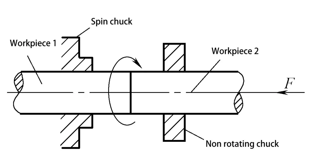
At the start of welding, workpiece 1 rotates at high speed while workpiece 2 moves towards and makes contact with workpiece 1. The mechanical energy consumed by the friction surfaces is converted into heat, raising the joint’s temperature to a certain level (thermoplastic state). At this point, workpiece 1 stops rotating, and a top pressure is applied to one end of workpiece 2, which cools under pressure to form a dense joint structure.
Friction welding joints are generally of equal cross-section, but they can also be of unequal cross-section, provided one cross-section is a rotating body.
1) Good and stable joint quality. The friction welding temperature is lower than the melting point of the workpiece metal, the heat-affected zone is small, and the joint completes plastic deformation and recrystallization under the top force, resulting in a dense structure.
Furthermore, the oxide film and oil contamination on the workpiece end face are wiped off by friction, making the joint less prone to porosity and slag inclusions, and thus improving the joint quality.
2) High welding productivity and low cost. Friction welding is simple to operate and does not require filler metal, making it easy to automate and leading to higher productivity. At the same time, the equipment is simple and energy consumption is low, only 1/10 to 1/5 of that of flash butt welding, resulting in lower costs.
3) Wide applicability. It is suitable not only for common ferrous and non-ferrous metals but also for welding special materials and dissimilar materials with significant differences in mechanical and physical properties at room temperature.
4) Good production conditions. Friction welding does not produce sparks, arc light, or dust, making it easy to operate and reducing labor intensity for workers.
As a fast and effective pressure welding method, friction welding is often used for butt welding of round workpieces, rods, and tubes. It can weld solid workpieces with diameters ranging from 2 to 100 mm, and tube outer diameters can reach several hundred millimeters. It has been widely used in tool production as well as in automobiles, tractors, oil drill rods, power stations, and textile machinery.
Because the initial investment for a friction welding machine is high, friction welding is suitable for large-scale production.
Explosion welding is a pressure welding method that uses the high pressure (700 MPa), high temperature (3000℃), and high-speed (500-1000 m/s) shock wave produced by the explosion of explosives to act on the cladding, causing it to violently collide with the base plate. This creates a jet at the point of contact, which removes surface oxides and other impurities, and forms a solid-state joint under high pressure.
As shown in Figure 4-31, any metal that has sufficient strength and plasticity and can withstand the rapid deformation required by the process can be explosion welded. The method can be divided into parallel and angle methods based on different assembly methods.
a) Parallel Method b) Angle Method
1-Detonator
2-Explosive
3-Buffer Layer
4-Cladding
5-Base Plate 6-Foundation
The quality of explosion welded joints is good, with a small heat-affected zone. It is primarily used for welding large composite plates and composite pipes, such as aluminum-steel-copper, titanium-steel, and zirconium-niobium, which are not suitable for other welding methods.
Ultrasonic welding is a form of pressure welding that utilizes the high-frequency oscillation energy of ultrasonics to locally heat and clean the joint of the workpieces, while pressure is applied to achieve welding, as illustrated in Figure 4-32.
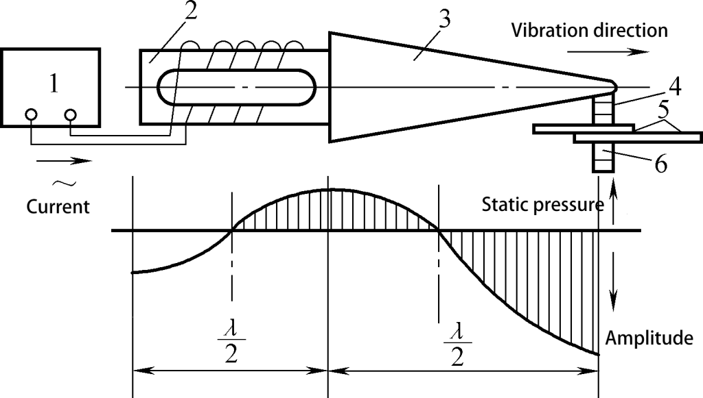
1 – Ultrasonic Generator
2 – Transducer
3 – Concentrator
4 – Upper Sound Pole
5 – Weldment
6 – Lower Sound Pole
During the welding process, ultrasonic waves generated by the ultrasonic generator reach the upper sound pole through a series of energy conversion and transmission steps. Under the influence of the oscillating poles, intense friction, temperature rise, and deformation occur at the local contact points of the two workpieces, thereby breaking or dispersing contaminants such as oxides, and bringing pure metal atoms close enough to form metallurgical bonds.
In the process of ultrasonic welding, no current flows through the workpieces, nor is there the influence of heat sources such as flame or arc light. It is a welding process that involves a combination of friction, diffusion, and plastic deformation. Ultrasonic welding can be divided into ultrasonic spot welding and ultrasonic seam welding.
Ultrasonic welding has a wide range of weldable materials and is particularly suitable for the welding of high melting point, high thermal conductivity, hard-to-melt metals, and dissimilar materials, as well as special structures such as those with significant thickness disparities and multilayer foils, such as 2μm gold foil, circuit leads of microelectronic devices, and so on.
It can also be used to weld plastics, such as PVC, polyethylene, nylon, and plexiglass, among others.
Brazing is a welding method that uses a metal filler material with a melting point lower than that of the base material. The workpiece and the filler material are heated to a temperature above the melting point of the filler material but below the melting point of the base material.
This process utilizes the liquid filler material to wet the base material, fill the joint gap, and mutually diffuse with the base material. Upon cooling, a connection is achieved.
Brazing is considered a physical connection, also known as brazing. The flux used in brazing is called brazing flux, which serves to remove oxides and other impurities from the surfaces of the filler and base materials.
It covers the surfaces of the workpiece and filler material in the form of a liquid film, isolating them from the air to protect the liquid filler material and the workpiece from oxidation. Additionally, it improves the wettability of the liquid filler material on the workpiece and enhances the filler material’s ability to fill gaps.
The fundamental difference between brazing and other welding methods is that the workpieces do not melt during the welding process. Instead, the connection is made by melting and filling the workpieces with a filler material that has a lower melting point.
The brazing process is divided into three stages: wetting, spreading, and joining, as shown in Figure 4-33.
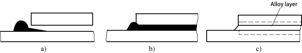
a) Wetting
b) Spreading
c) Joining
Brazing can be divided into soft brazing and hard brazing based on the melting point of the filler material.
(1) Soft brazing
Soft brazing uses filler materials with melting points below 450°C, resulting in joints with lower strength, typically between 60 and 190 MPa, and are suitable for operating temperatures below 100°C. These fillers have a strong capability to penetrate into joint gaps and exhibit good welding processability.
Common soft brazing fillers include tin-lead alloys, also known as tin soldering. Tin brazing fillers are highly conductive, making them primarily used for connecting components in electronic circuits. The fluxes used in soft brazing mainly include rosin and zinc chloride solutions.
(2) Hard brazing
Hard brazing employs filler materials with melting points above 450°C, yielding joints with higher strength, all exceeding 200 MPa, and capable of withstanding higher operating temperatures.
Common hard brazing fillers include aluminum-based, silver-based, and copper-based alloys, with fluxes primarily consisting of borax, boric acid, fluorides, and chlorides.
The joint configurations in brazing include sheet metal overlap, sleeve insertion, and others. These joints feature large brazed surfaces, ensuring good load-bearing capacity.
Brazing heating methods include flame heating, resistance heating, induction heating, furnace heating, salt bath heating, and soldering iron heating. The choice of heating method can be determined based on factors such as the type of filler material, the shape and size of the workpiece, the number of joints, quality requirements, and production volume.
Among these, soldering iron heating generates lower temperatures and is generally suitable only for soft brazing.