Oppervlaktekwaliteit verbeteren bij machinale bewerking: Sleuteltechnieken
De oppervlaktekwaliteit van machinale bewerking verwijst naar de oppervlaktegesteldheid van het onderdeel na machinale bewerking. De...
Different welding methods have different parameters, and even the same welding method can have different parameters due to different working conditions, workpiece sizes, shapes, materials, and weld positions during welding. Therefore, the following is a brief introduction to the principles of selecting welding parameters for commonly used welding methods.
The determination of welding parameters mainly considers the following aspects:
See the commonly used welding methods described.
When other welding parameters remain unchanged, increasing the welding current will increase both the thickness and the reinforcement of the weld, while the width of the weld remains almost unchanged (or slightly increases), as shown in Figure 2-67. If the welding current is too high, there may be defects such as burn-through or excessive reinforcement. When the welding current is reduced, the thickness of the weld will decrease, and the welding penetration will worsen.
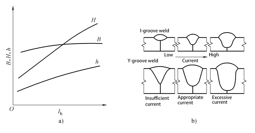
a) Influence of rules b) Changes in weld shape
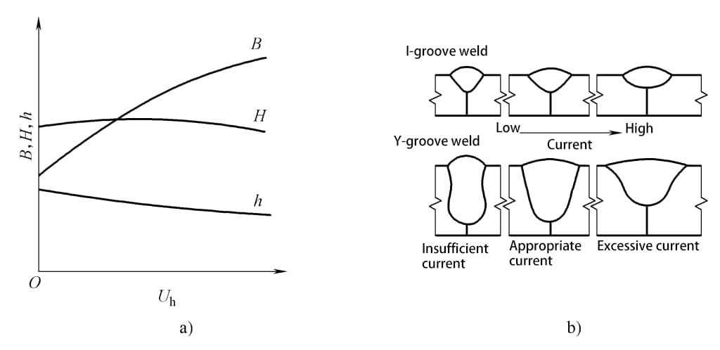
When other welding parameters remain unchanged, an increase in arc voltage significantly increases the weld width while the weld thickness and reinforcement slightly decrease, as shown in Figure 2-68. It can be seen that the welding current is the main factor determining the weld thickness, while the arc voltage is the main factor affecting the weld width.
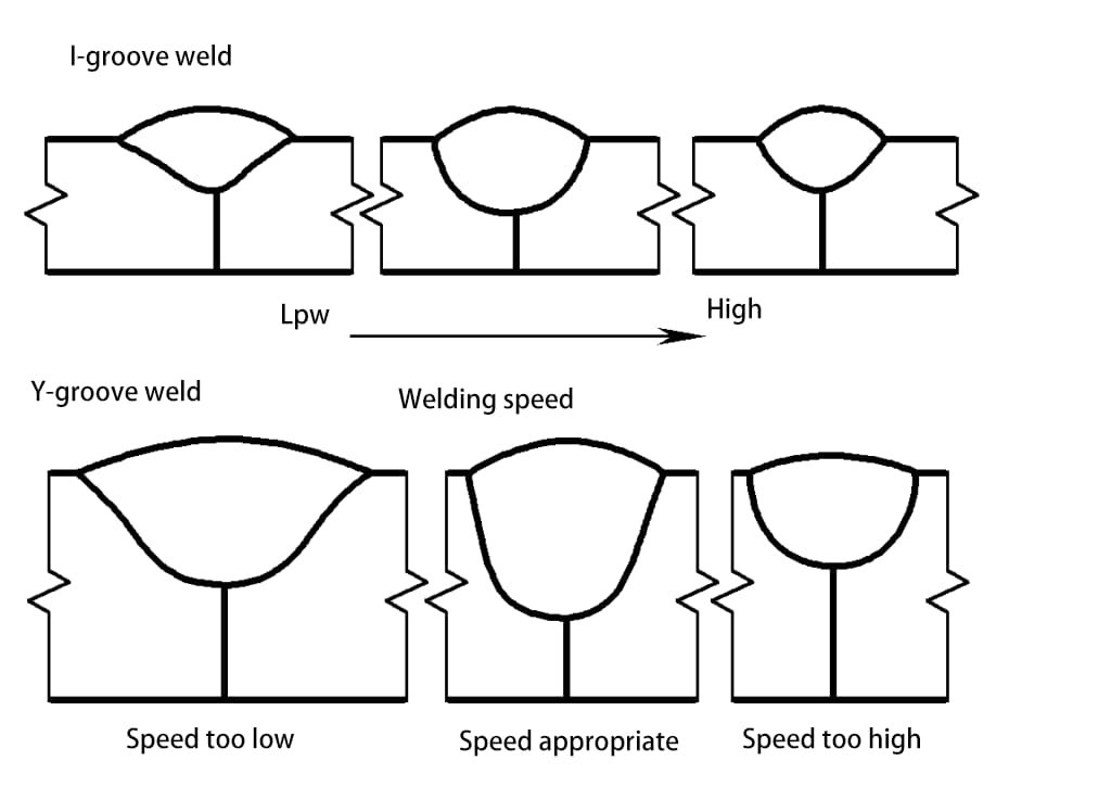
Welding speed has a significant impact on both weld thickness and width, as shown in Figure 2-69. When the welding speed increases, both the weld thickness and width significantly decrease.
In addition to the three main welding parameters mentioned above, some other welding parameters also have a certain impact on the weld shape.
(1) Electrode diameter and wire extension length
Reducing the electrode diameter will decrease the weld thickness and weld width. As the wire extension length increases, the reinforcement increases. The smaller the wire diameter or the higher the material resistivity, the more pronounced this effect.
(2) Electrode inclination
During welding, the electrode (or wire) is tilted relative to the workpiece so that the arc always points to the part to be welded. This method of welding is called forehand welding. With forehand, the weld formation factor increases, penetration is shallow, weld width increases, and reinforcement decreases. The smaller the forehand angle α, the more pronounced this effect, as shown in Figure 2-70. This method is suitable for welding thin plates. When the electrode (wire) is tilted backward, the situation is the opposite.
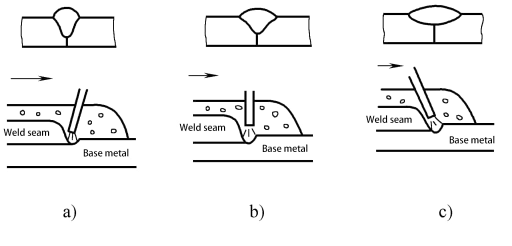
a) Wire tilted backward b) Wire vertical c) Wire tilted forward
(3) Workpiece inclination
When performing uphill welding, the weld thickness and reinforcement increase, while the weld width decreases. The greater the uphill angle, the more pronounced the effect. When the uphill angle α > 6°, the formation deteriorates. Therefore, in automatic arc welding, it is always practically avoided to use uphill welding.
The situation with downhill welding is just the opposite, that is, the weld thickness and reinforcement slightly decrease, while the weld width slightly increases. Therefore, downhill welding with an inclination angle α < 6° can improve the surface weld formation. When welding thin plates with shielded metal arc welding, downhill welding is often used. If the inclination angle is too large, it can lead to incomplete penetration and overflow of molten metal in the weld pool, deteriorating the weld formation, as shown in Figure 2-71.
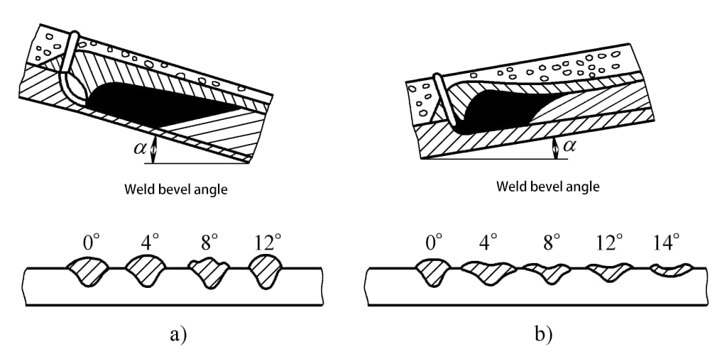
a) Uphill welding b) Downhill welding
(4) Groove shape
When other welding parameters remain unchanged, increasing the depth and width of the groove slightly increases the thickness of the weld, slightly reduces the width of the weld, and significantly reduces the reinforcement, as shown in Figure 2-72.
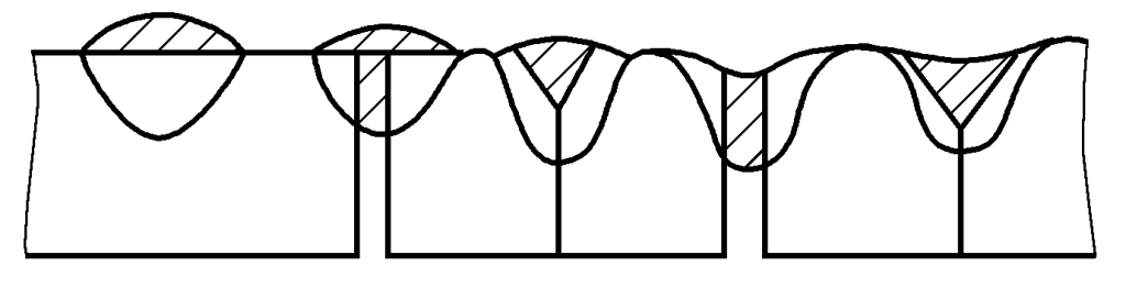
(The shaded area in the figure represents the area occupied by the electrode deposited metal)
(5) Flux
In booglassen onder poederdek, the composition, density, granularity, and stacking height of the flux all have a certain impact on the shape of the weld. When other conditions are the same, fluxes with poor arc stability produce thicker welds, while the width of the weld is smaller. When the flux density is low, the granularity is large, or the stacking height is reduced, the arc swing range expands, thus reducing the thickness of the weld, increasing the width of the weld, and slightly reducing the reinforcement.
Moreover, excessive viscosity of the slag results in poor air permeability of the slag, making it difficult for gases to escape during the solidification of the molten pool, leading to the formation of many pits on the surface of the weld and deteriorating the formation.
(6) Shielding gas composition
In gas shielded welding, the composition of the shielding gas and the closely related droplet transition form have a significant impact on the shape of the weld. The changes in weld shape when using different shielding gases for reverse polarity gas shielded metal arc welding are shown in Figure 2-73.
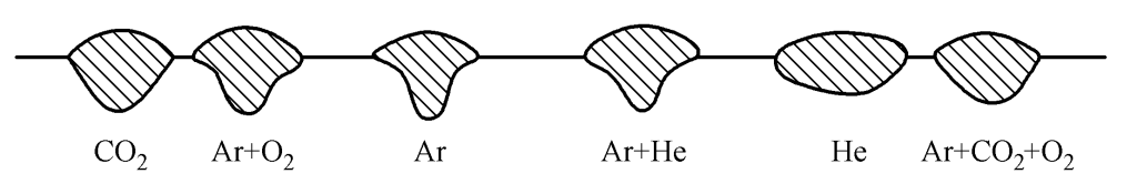
Jet transition argon arc welding always forms obvious mushroom-shaped welds. Adding O, CO, or H to argon can widen the root formation and slightly increase the thickness of the weld. Granular and short-circuit transition arc welding forms a wide and shallow weld shape.
(7) Chemical composition of the base material
The chemical composition of the base material varies, and under the same other process factors, the shape of the weld is different, which is particularly evident in argon arc welding. For example, three different origins of 06Cr19Ni10 and 06Cr17Ni12Mo2 stainless steels, when welded by the tungsten electrode argon arc welding method with the same welding parameters, the changes in the weld shape obtained are shown in Table 2-24.
Table 2-24 Influence of Base Material Chemical Composition on Weld Shape
| Nee. | Chemical composition of the base material (mass fraction, %) | Weld thickness/mm | Weld width/mm | Arc voltage/V | |||||||
| C | Si | Mn | P | S | Cr | Mo | Ni | ||||
| 1 | 0.034 | 0.55 | 1.63 | 0.03 | 0.002 | 17.2 | 2.65 | 11.4 | 2.5 | 6.8 | 15.1 |
| 2 | 0.037 | 0.63 | 0.93 | 0.018 | 0.02 | 16 | 2.18 | 10.2 | 1.7 | 6.8 | 14.9 |
| 3 | 0.042 | 0.45 | 1.65 | 0.032 | 0.012 | 16.3 | 2.62 | 11.5 | 1.6 | 6.6 | 14.9 |
| 4 | 0.041 | 0.67 | 1.66 | 0.031 | 0.014 | 17.8 | - | 8.6 | 3 | 5.2 | 15.1 |
| 5 | 0.036 | 0.4 | 1.54 | 0.035 | 0.11 | 18 | - | 8.8 | 2.3 | 6.5 | 15.2 |
| 6 | 0.44 | 0.6 | 0.99 | 0.016 | 0.004 | 17.8 | - | 9.1 | 1.3 | 6.9 | 14.7 |
Note: Tungsten rod end 45°, arc length 2mm, current 150A, welding speed 300mm/min