Comprehensive Guide to Seam Welding Techniques
Imagine a world where the strength and integrity of countless everyday products hinge on an unassuming yet vital process: seam…
A weld seam refers to the joint part formed in the welded component after welding. The metal that makes up the weld seam, i.e., the weld metal, directly affects the performance of the welded components and structures due to its shape and quality. Therefore, welders should understand the types of weld seams and their representation symbols on engineering drawings.
(1) According to different joint forms, it can be divided into five types: butt weld, fillet weld, plug weld, groove weld, and edge weld.
1) Butt weld.
A weld seam welded between the bevel surfaces of the workpieces or between the bevel surface of one part and the surface of another part.
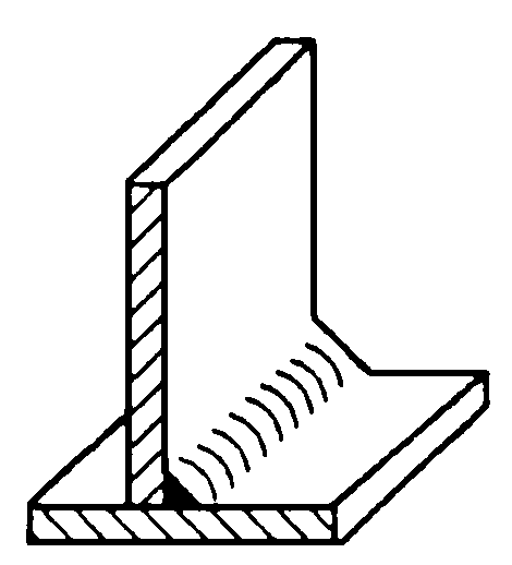
2) Fillet weld.
A weld seam welded along the intersection line of two orthogonal or nearly orthogonal parts.
3) Terminal weld seam.
The weld seam formed by a terminal joint.
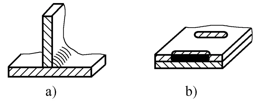
4) Plug weld seam.
Two parts are overlapped, one of which has a round hole, and the weld seam formed by welding the two plates in the round hole, only the fillet weld inside the hole is not considered a plug weld.
5) Slot weld seam.
Two plates are overlapped, one of which has a long hole, and the weld seam formed by welding the two plates in the long hole, only the fillet weld is not considered a slot weld.
(2) According to the different spatial positions of the weld seam
Can be divided into flat weld seam, vertical weld seam, horizontal weld seam, and overhead weld seam four forms.
(3) According to the different continuity of the weld seam
Divided into continuous welds and intermittent welds. Intermittent welds are further divided into staggered and parallel types, as shown in Figure 2-50. In addition to specifying the size of the weld toe K, the length L and spacing e of each segment of the intermittent weld should also be indicated, and the symbol “Z” represents the staggered weld.
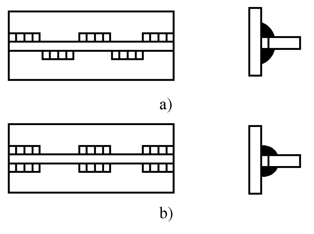
a) Staggered
b) Parallel
(4) According to the different functions of the weld
Divided into load-bearing welds that bear loads, connecting welds that do not directly bear loads but only serve to connect, sealing welds mainly used to prevent fluid leakage, and positioning welds that are welded before formal welding to assemble and fix the position of joints on the workpiece with a shorter length.
(5) According to the shape of the weld and its position at the joint
Divided into butt welds that form butt joints; edge welds applied at the edge rolling of the workpiece; plug welds formed by welding in a round hole opened in one of two overlapped plates; circumferential welds distributed along the circumference of spherical or cylindrical workpieces with ends joined together; and flush welds whose surfaces are ground to be flush with the surface of the base material, etc.
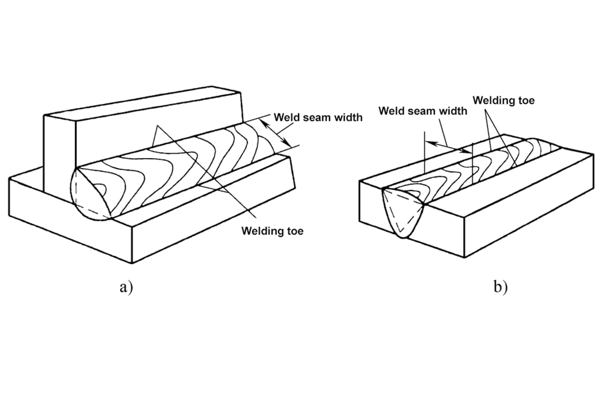
(1) Weld width
The junction between the weld surface and the base material is called the weld toe. In the cross-section of a single-pass weld, the distance between the two weld toes is called the weld width, as shown in Figure 2-51.
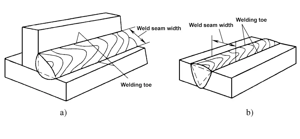
a) T-joint
b) Butt joint
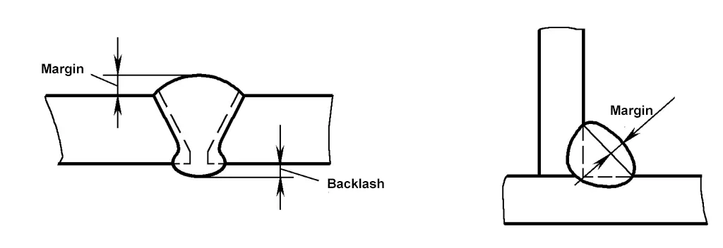
(2) Excess Height
In butt welds, the height of the weld metal above the line connecting the surface weld toes is called excess height, as shown in Figure 2-52. Excess height increases the cross-sectional area of the weld, improves strength, and can increase the sensitivity of X-ray films, but it is prone to stress concentration at the weld toes. Therefore, the excess height should not be lower than the base material, but also not too high. The national standard specifies that the excess height for shielded metal arc welding is 0~3mm, and for submerged arc welding, the excess height is 0~4mm.
(3) Penetration Depth
In the cross-section of the welded joint, the depth of melting of the base material is called penetration depth, as shown in Figure 2-53. When the filler metal material (welding rod or wire) is fixed, the size of the penetration depth is determined by the chemical composition of the weld.
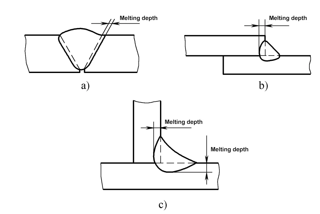
a) Butt joint fusion depth
b) Lap joint fusion depth
c) T-joint fusion depth
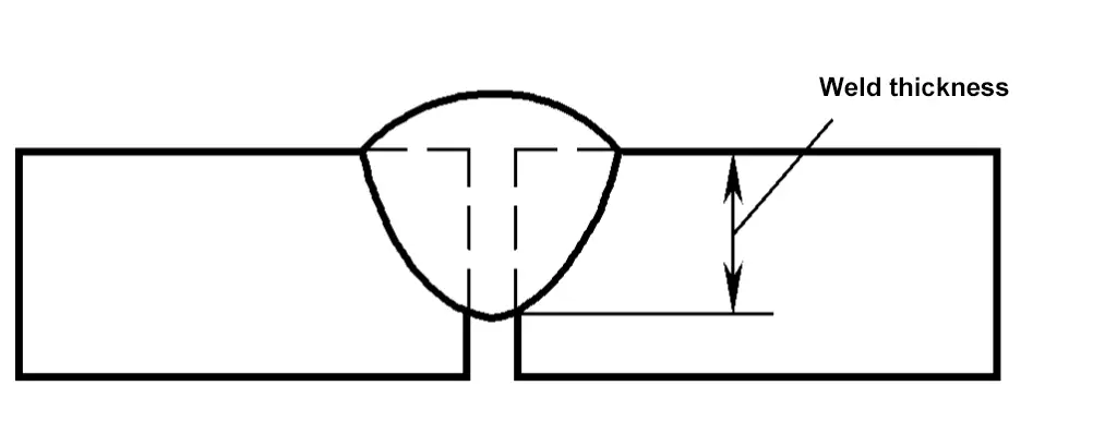
(4) Weld thickness
In the cross-section of the weld, the distance from the front of the weld to the back of the weld is called the weld thickness, as shown in Figure 2-54.
(5) Shape and size of fillet welds
Based on the external shape of the fillet weld, fillet welds can be divided into two types: fillet welds with a raised surface are called convex fillet welds; fillet welds with a concave surface are called concave fillet welds, as shown in Figure 2-55. Under certain conditions, concave fillet welds have much less stress concentration than convex fillet welds.
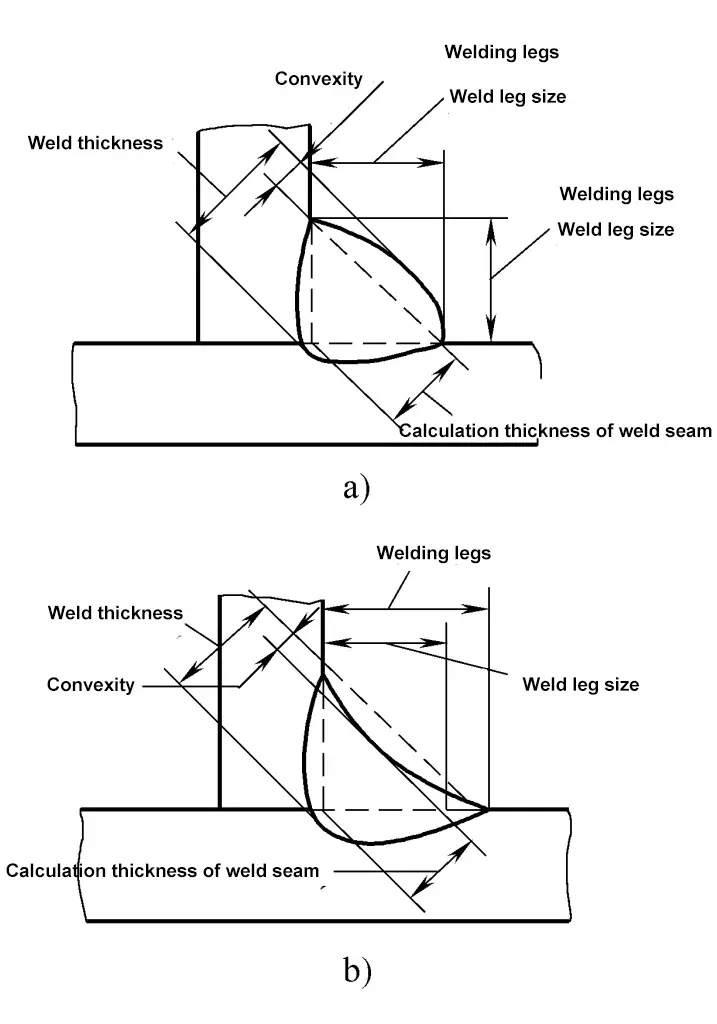
a) Convex fillet weld
b) Concave fillet weld
1) Weld calculation thickness.
Draw the largest right-angled isosceles triangle within the cross-section of the fillet weld, the perpendicular length from the right-angle vertex to the hypotenuse is the weld calculation thickness. If the cross-section of the fillet weld is a standard isosceles right triangle, then the weld calculation thickness is equal to the weld thickness; in convex or concave fillet welds, the weld calculation thickness is less than the weld thickness.
2) Weld convexity.
In the cross-section of a convex fillet weld, the maximum distance between the weld toe line and the weld surface, as shown in Figure 2-55.
3) Weld concavity.
In the cross-section of a concave fillet weld, the maximum distance between the weld toe line and the weld surface, as shown in Figure 2-55b.
4) Weld leg.
In the cross-section of a fillet weld, the minimum distance from a weld toe on one workpiece to the surface of another workpiece; the weld leg size is the length of the right-angle side in the largest isosceles right triangle drawn in the cross-section, for convex fillet welds, the weld leg size is equal to the weld leg; for concave fillet welds, the weld leg size is less than the weld leg.
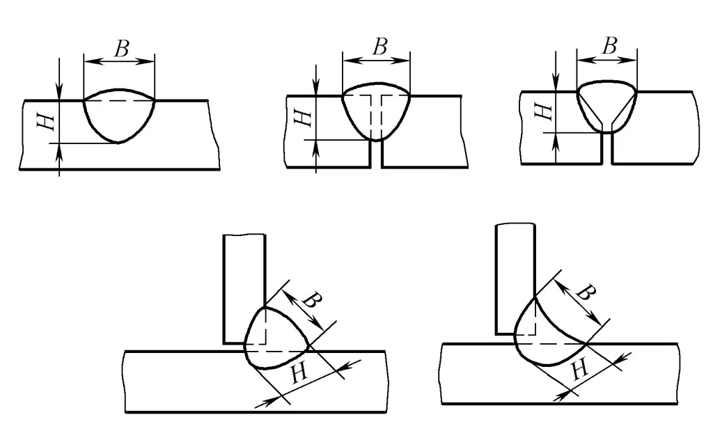
(6) Weld formation factor
During welding, the ratio of the weld width (B) to the calculated thickness of the weld (H) on the cross-section of a single weld seam (ψ=B/H) is called the weld formation factor, as shown in Figure 2-56. The smaller the weld formation factor, the narrower and deeper the weld, which makes it prone to porosity, slag inclusion, and cracking. Therefore, the weld formation factor should maintain a certain value, for example, the weld formation factor for submerged arc welding should be greater than 1.3.
(7) Fusion Ratio
Refers to the percentage of the base material that is melted into the weld metal during welding.
Where:
When welding high alloy steel and non-ferrous metals, the fusion ratio should be controlled to prevent welding defects.
The symbols used to mark the welding method, weld form, and weld dimensions on drawings are called weld symbols. Weld symbols generally consist of basic symbols and leader lines. Auxiliary symbols, supplementary symbols, and weld dimension symbols may also be added as necessary. According to the provisions of GB/T324-2008 “Representation of Weld Symbols”, weld symbols can be divided into the following types.
Basic symbols are used to represent the cross-sectional shape or characteristics of welds, see Table 2-13. The application of basic symbols is shown in Table 2-14.
| No. | Name | Schematic diagram | Symbol |
| 1 | Edge-flanged weld (with complete edge fusion) | 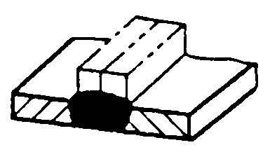 |  |
| 2 | I-shaped weld | 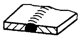 |  |
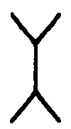
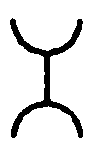
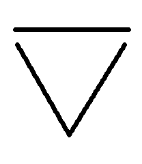
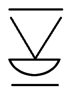
| 3 | V-shaped weld | 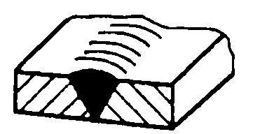 |  |
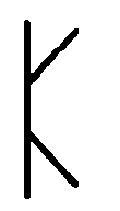
| 4 | Single-bevel V-shaped weld | 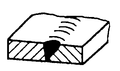 | 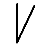 |
| 5 | V-shaped weld with blunt edge | 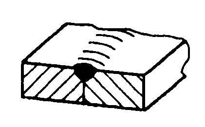 | 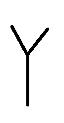 |
| 6 | Single-bevel V-shaped weld with blunt edge | 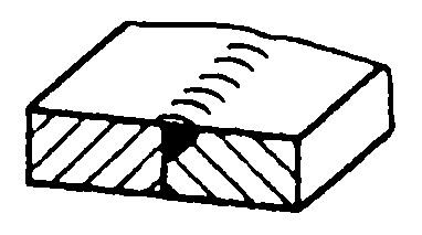 | 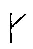 |
| 7 | U-shaped weld with blunt edge | 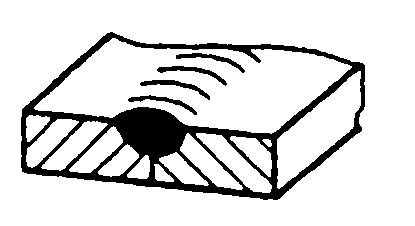 | 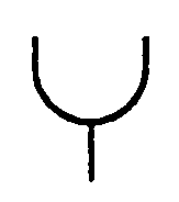 |
| 8 | J-shaped weld with blunt edge | 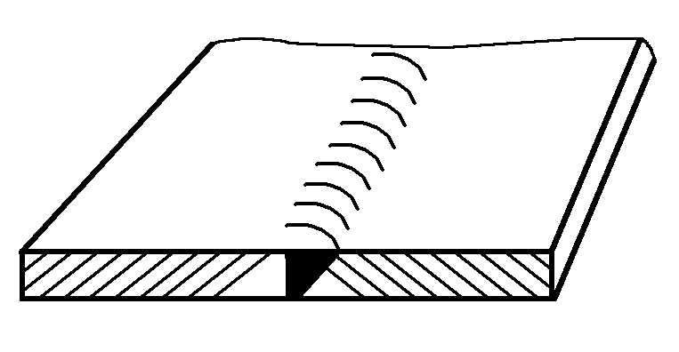 | 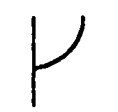 |
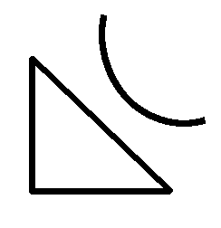
| 9 | Backing weld | 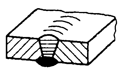 | 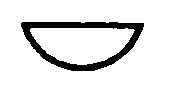 |
| 10 | Fillet weld | 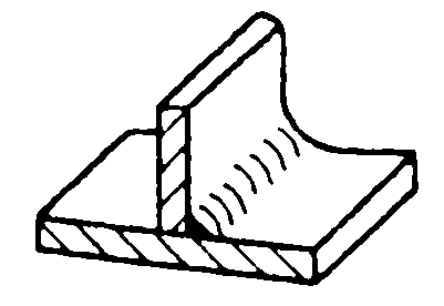 | 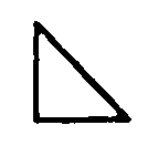 |
| 11 | Plug weld or slot weld | 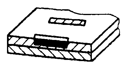 |  |
| 12 | Spot weld | 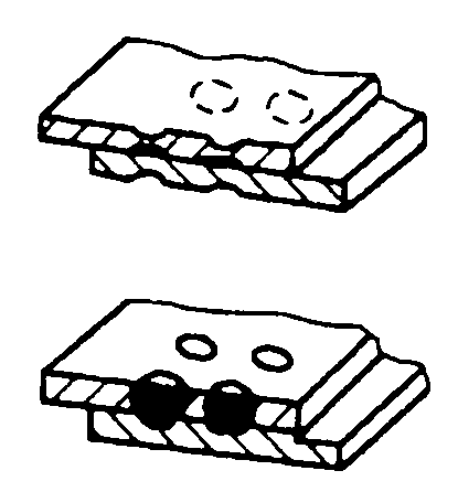 |  |
| 13 | Seam weld | 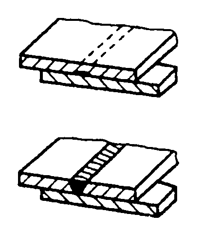 | 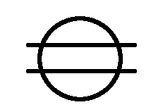 |
| 14 | Steep-flanked V-shaped weld | 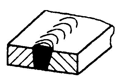 | 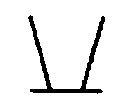 |
| 15 | Steep-flanked single V-shaped weld | 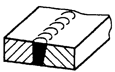 | 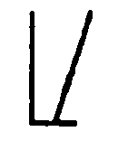 |
| 16 | End weld | 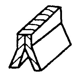 | 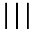 |
| 17 | Build-up weld | 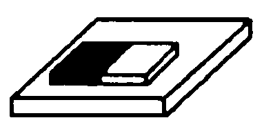 | 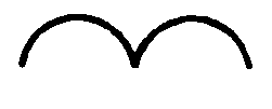 |
| 18 | Flat brazed joint | 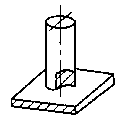 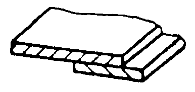 |  |
| 19 | Beveled brazed joint | 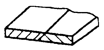 |  |
| 20 | Folded brazed joint | 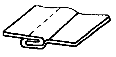 |  |
Table 2-14: Examples of Basic Symbol ApplicationsNo. Symbol Diagram Annotation Example 1 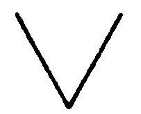
2 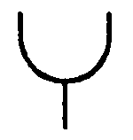
3 
4 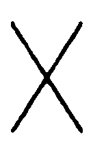
5 
Note: When welding double-sided welds or joints, basic symbols can be combined, see Table 2-15.
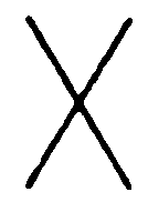
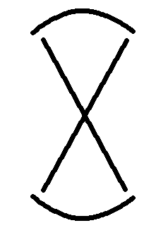
Table 2-15 Combination of Basic SymbolsNo. Symbol Diagram Annotation Example 1 Double-sided V-groove weld (X-weld) 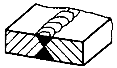
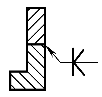
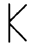
2 Double-sided single V-groove weld (K-weld) 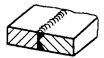
3 Double-sided V-groove weld with a blunt edge 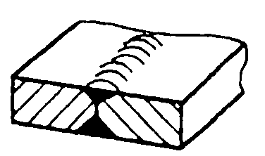
4 Double-sided single V-groove weld with a blunt edge 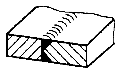
5 Double-sided U-groove weld 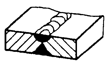
Supplementary symbols are used to provide additional information about certain characteristics of welds or joints (such as surface shape, backing, weld distribution, welding location, etc.).
1) See Table 2-16 for supplementary symbols.
Table 2-16 Supplementary SymbolsNo. Name Symbol Description 1 Flat ![]()
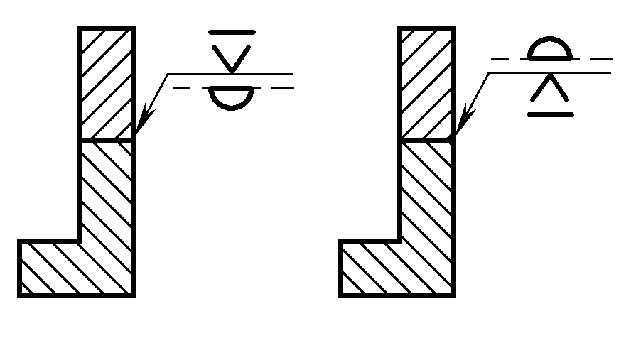
The weld seam surface is usually machined to be flat. 2 Concave 
The weld seam surface is recessed. 3 Convex 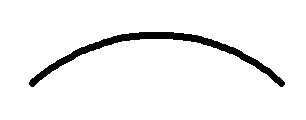
The weld seam surface protrudes. 4 Smooth Transition 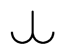
The transition at the weld toe is smooth. 5 Permanent Backing 
The backing is permanently retained. 6 Temporary Backing 
The backing is removed after welding is completed. 7 Three-Sided Weld 
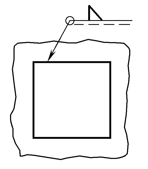
The weld is present on three sides. 8 Peripheral Weld 
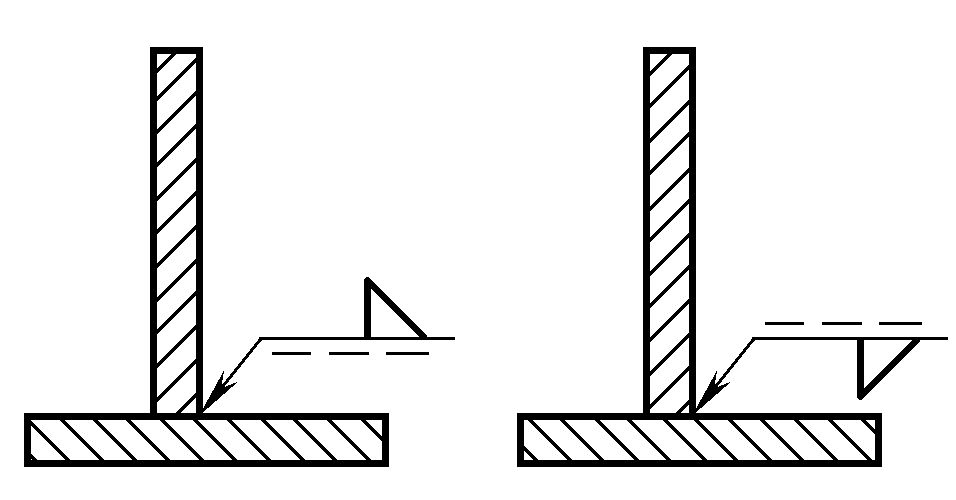
A weld applied along the perimeter of the workpiece; the location is marked at the intersection of the baseline and the arrow line. 9 Field Weld 
A weld executed on-site. 10 Tail 
Can indicate the required information.
2) Tables 2-17 and 2-18 provide examples of the application and marking of supplementary symbols.
Table 2-17 Examples of Application of Supplementary SymbolsNo. Name Symbol Description 1 Flat V-groove weld 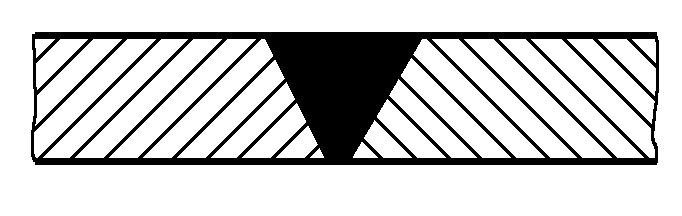
2 Raised double V-groove weld 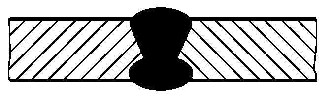
3 Recessed fillet weld 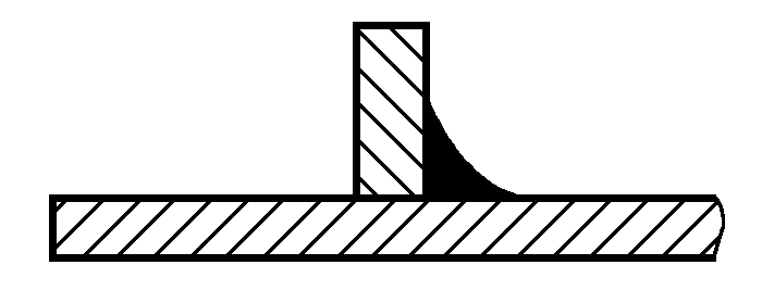
4 Flat V-groove weld with a backing weld 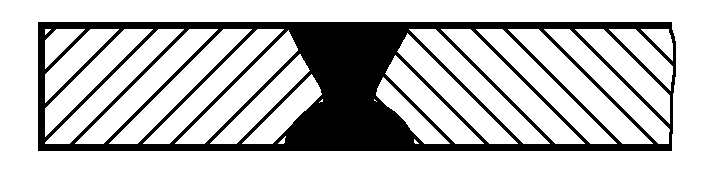
5 Fillet weld with a smooth surface transition 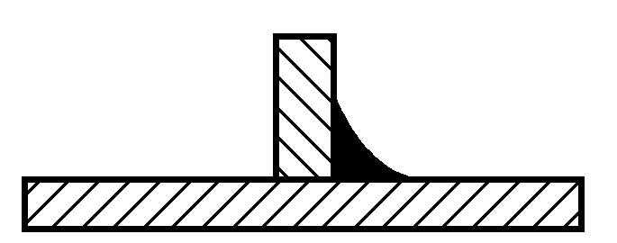
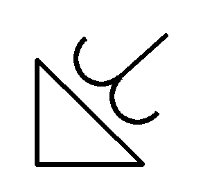
Table 2-18 Examples of Marking of Supplementary SymbolsNo. Symbol Diagram Annotation Example 1 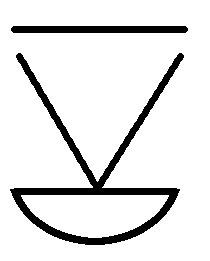
2 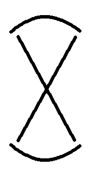
3 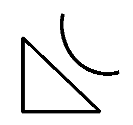
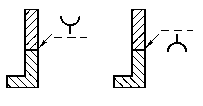
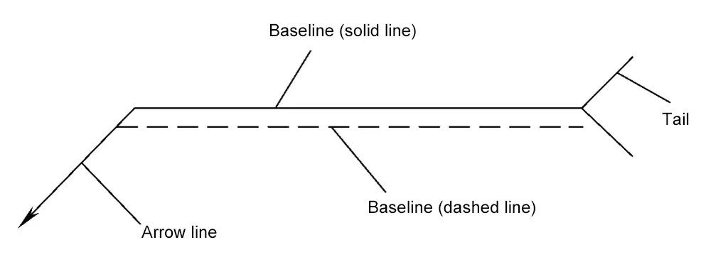
The leader line consists of an arrow line, reference lines (solid and dashed), and a tail, as shown in Figure 2-57.
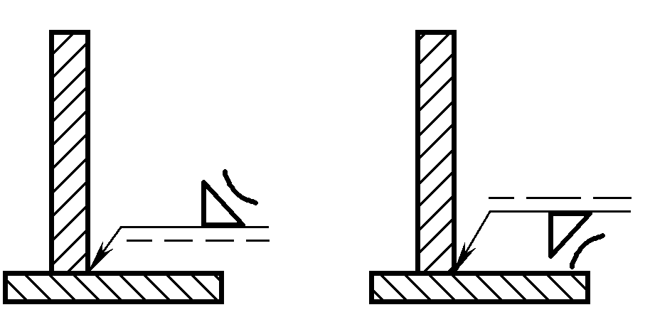
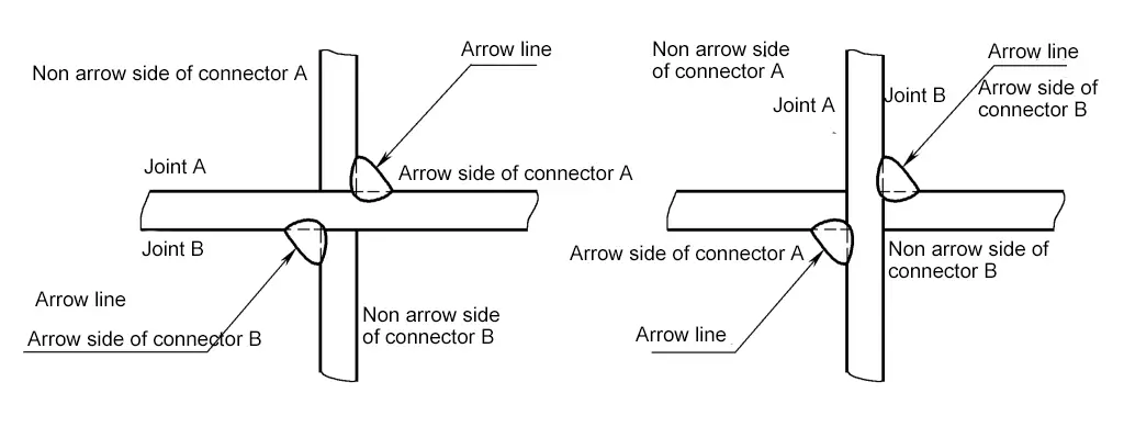
(1) Arrow Line
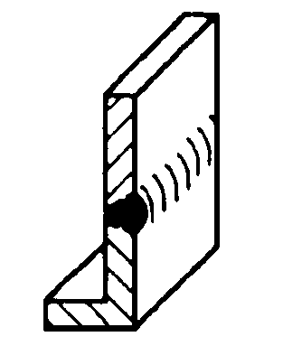
The joint directly pointed to by the arrow is the “arrow side” of the joint, and the opposite side is the “non-arrow side” of the joint, as shown in Figure 2-58.
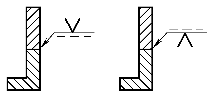
(2) Datum Line
The datum line should generally be parallel to the bottom edge of the drawing, but can also be perpendicular if necessary. The positions of solid and dashed lines can be interchanged as needed. When marking symmetrical welds or double-sided welds, dashed lines can be omitted.
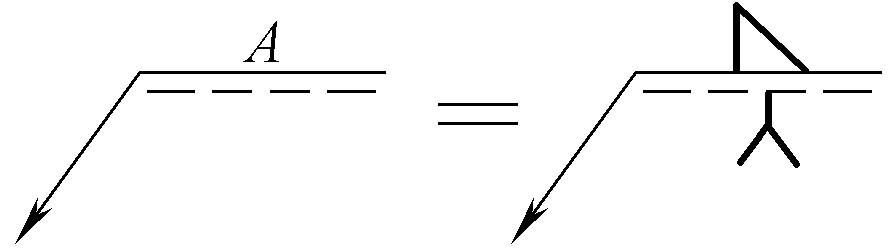
(3) Tail
Generally omitted. The tail part is only added when there are additional requirements or explanations for the weld.
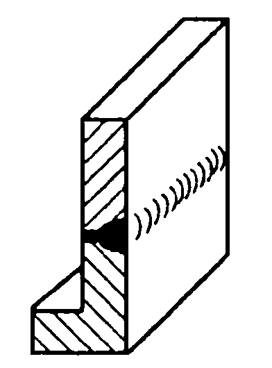
When it is necessary to simply draw welds in the drawing, they can be represented by views, sectional views, or cross-sectional views, or can be schematically represented by isometric drawings.
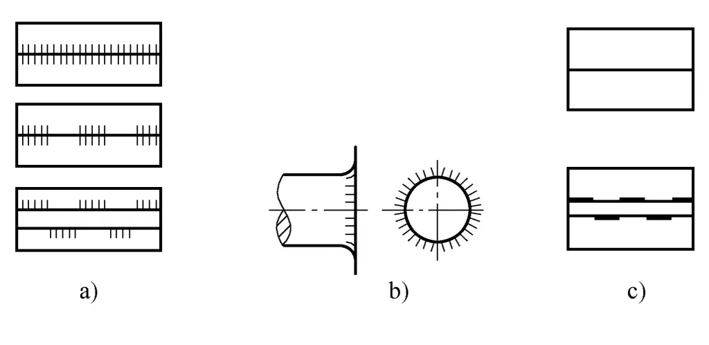
When representing welds with a view, the drawing method is as shown in Figure 2-59, where the welds represented by Figure 2-59a and b series of solid lines are allowed to be drawn by hand; the weld represented by Figure 2-59c is indicated with a thick line.
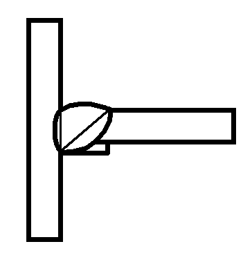
In the view representing the weld surface, the outline of the weld is usually drawn with a thick solid line. If necessary, the shape of the bevel before welding can be drawn with a thin solid line, as shown in Figure 2-60.
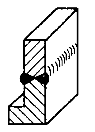
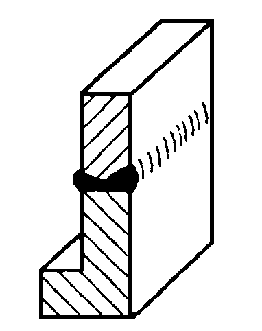
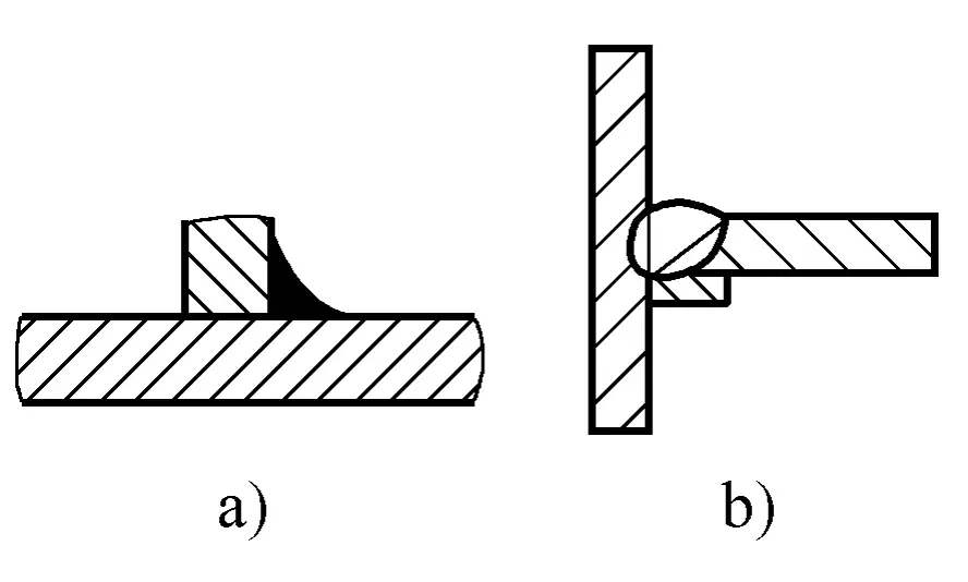
In a sectional view or cross-sectional view, the metal fusion zone of the weld is usually shaded in black, as shown in Figure 2-61a. If it is also necessary to represent the shape of the bevel, etc., the fusion zone part is usually outlined with a thick solid line, and if necessary, the shape of the bevel before welding is drawn with a thin solid line, as shown in Figure 2-61b.
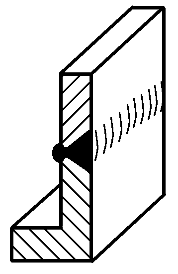
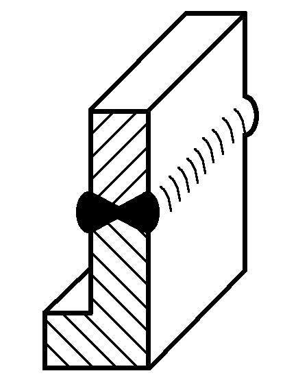
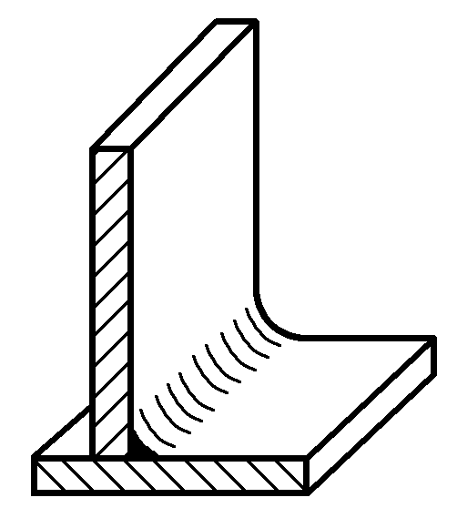
The method of representing welds with an isometric drawing is as shown in Figure 2-62.
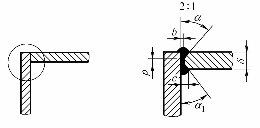
When necessary, the weld area can be enlarged and labeled as shown in Figure 2-63.
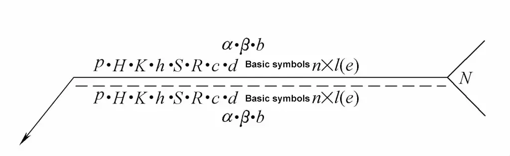
1) Horizontal dimensions are labeled on the left side of the basic symbol.
2) Vertical dimensions are labeled on the right side of the basic symbol.
3) Bevel angle, groove angle, and root gap are labeled on the top or bottom of the basic symbol.
4) The quantity of identical welds is labeled at the end.
5) When there are many dimensions that are difficult to distinguish, the corresponding dimension symbols can be marked in front of the dimension data.
6) The dimensions determining the weld position should not be marked in the weld symbol, but should be marked on the drawing.
7) When there are no dimension markings on the right side of the basic symbol and no other instructions, it means that the weld is continuous along the entire length of the workpiece.
8) When there are no dimension markings on the left side of the basic symbol and no other instructions, it means that the butt weld should be fully penetrated.
9) When plug welds and slot welds have beveled edges, the dimensions of their bottom should be marked.
The method of marking weld dimension symbols is shown in Figure 2-64.
The common weld dimension symbols are shown in Table 2-19.
Table 2-19 Common Weld Seam Size SymbolsSymbol Name Diagram δ Workpiece Thickness 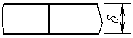
α Bevel Angle 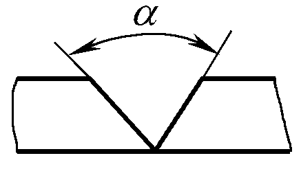
β Bevel Face Angle 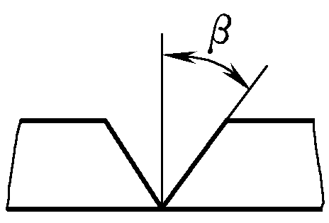
b Root Gap 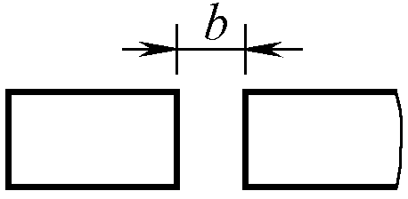
P Blunt Edge 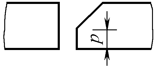
R Root Radius 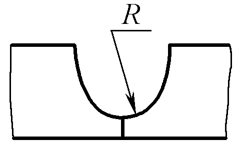
H Bevel Depth 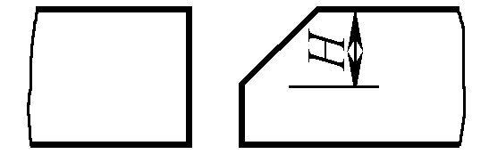
S Effective Weld Thickness 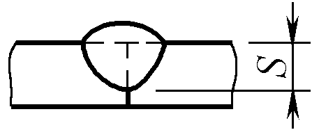
c Weld Width 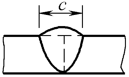
K Weld Toe Size 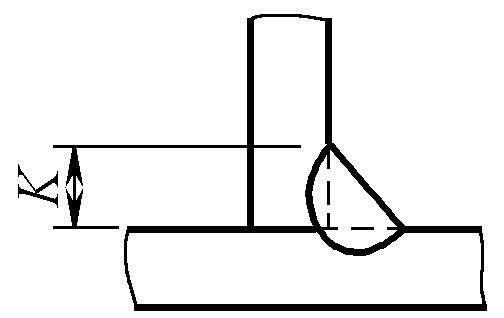
d Spot Weld: Nugget Diameter
Plug Weld: Hole Diameter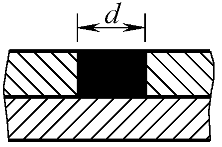
n Number of Weld Segments 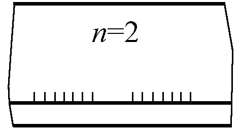
l Weld Length 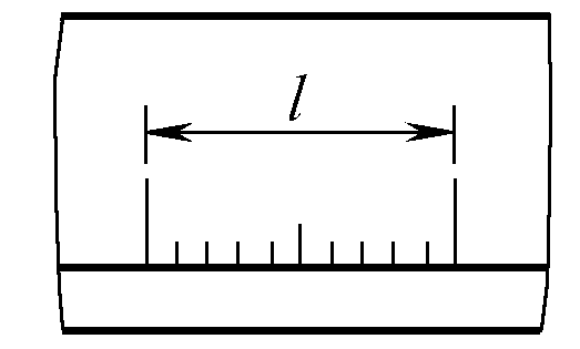
e Weld Spacing 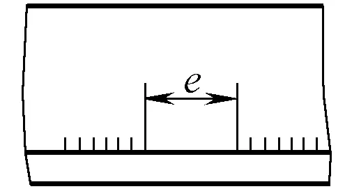
N Number of Identical Welds 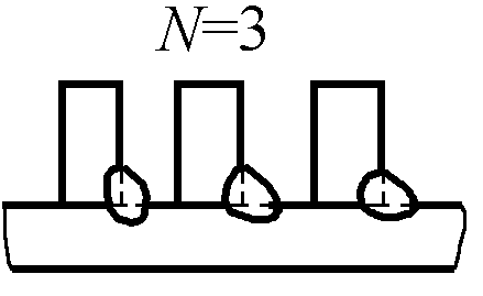
h Excess Height 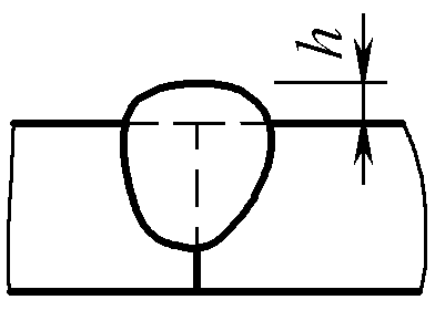
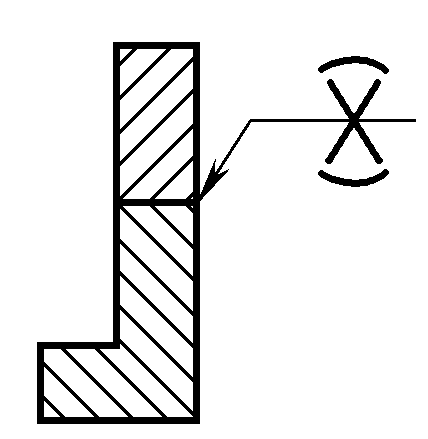
1) Peripheral weld.
When the weld seam surrounds the workpiece, a circular symbol can be used, as shown in Figure 2-65.
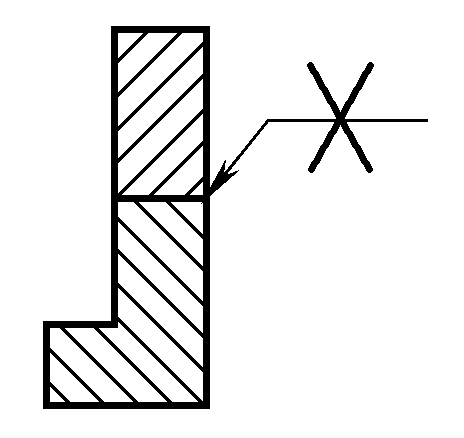
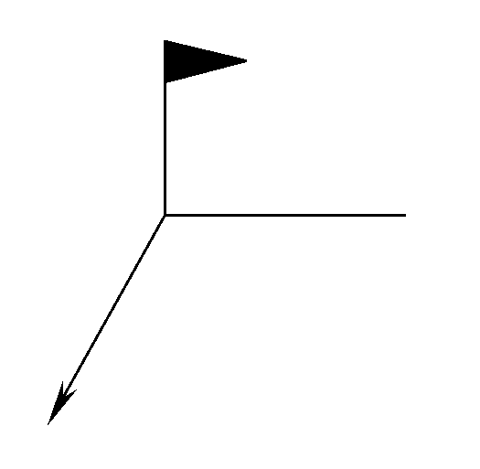
2) Field weld.
A small flag represents a field or on-site weld, as shown in Figure 2-66.
The application of weld seam symbol size annotation is shown in Table 2-20.
| No. | Name | Diagram | Dimension Symbol | Annotation Method |
| 1 | Butt Weld | 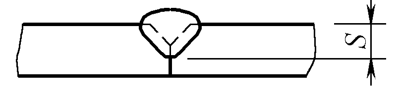 | S: Effective Thickness of Weld | 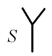 |
| 2 | Continuous Fillet Weld | 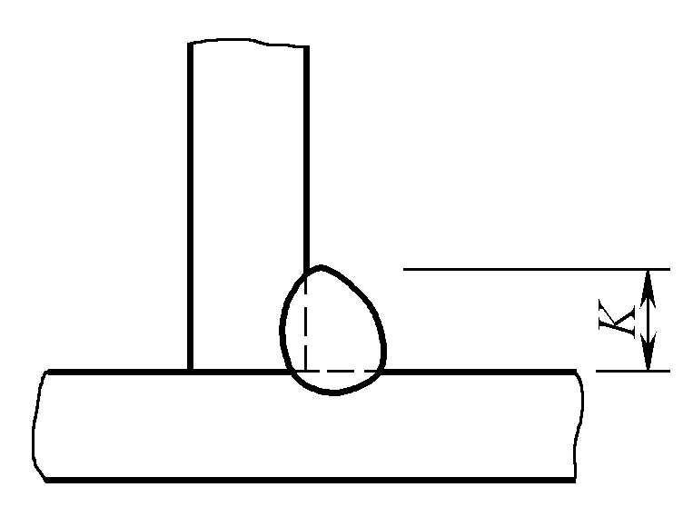 | K: Size of Weld Leg | 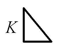 |
| 3 | Intermittent Fillet Weld | 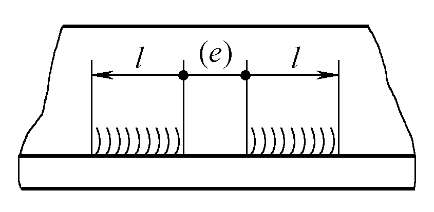 | I: Weld Length e: Spacing n: Number of Weld Segments K: Size of Weld Leg | 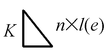 |
| 4 | Staggered Intermittent Fillet Weld | 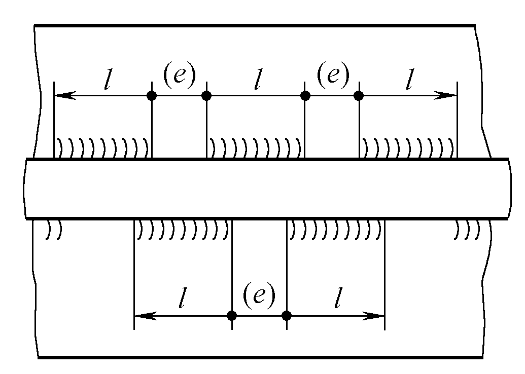 | l: Weld Length e: Spacing n: Number of Weld Segments K: Size of Weld Leg | 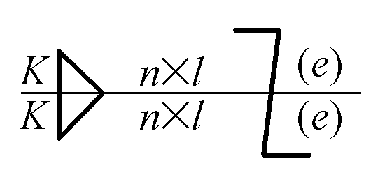 |
| 5 | Plug Weld or Slot Weld | 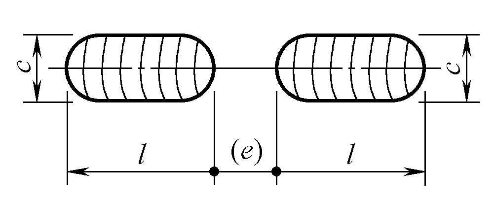 | l: Weld Length e: Spacing n: Number of Weld Segments c: Slot Width | 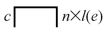 |
 | e: Spacing n: Number of Weld Segments d: Hole Diameter | 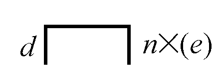 | ||
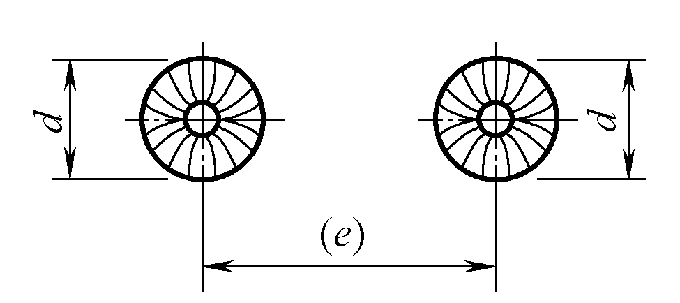
| 6 | Spot Weld | 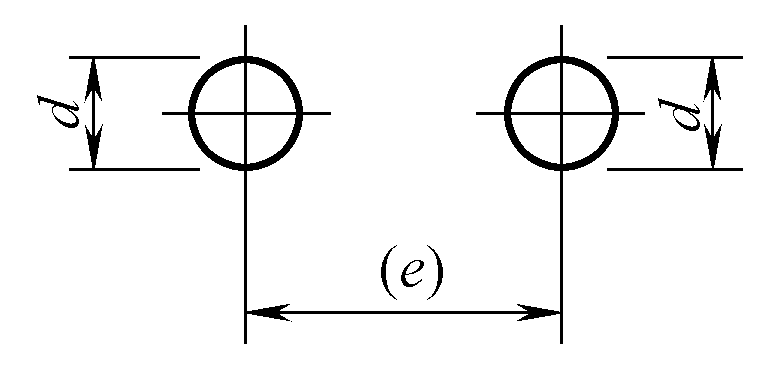 | n: Number of Weld Spots e: Distance Between Weld Spots d: Fusion Core Diameter | 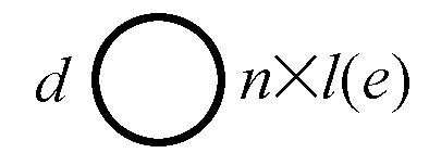 |
| 7 | Seam Weld | 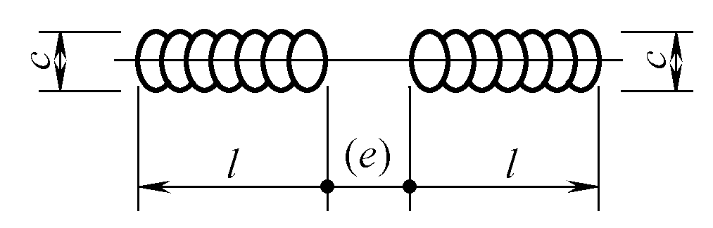 | l: Weld Length e: Spacing n: Number of Weld Segments c: Weld Width | 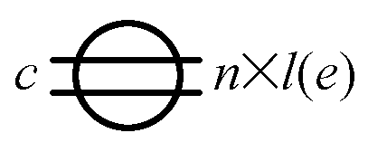 |
The simplified notation method for weld symbols is shown in Table 2-21.
Table 2-21 Simplified notation method for weld symbolsNo. Annotation method Explanation Diagram 1 Single Annotation When annotating the size of staggered symmetric welds in a weld symbol, it is permissible to annotate on the reference line just once. 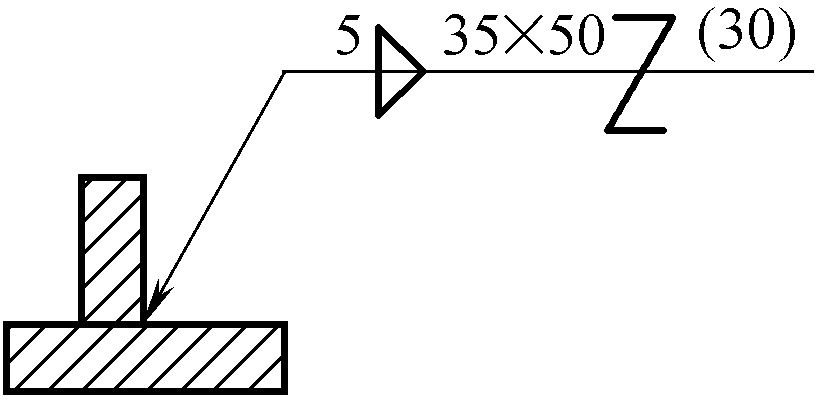
2 Omission of Segment Count Annotation When there is no strict requirement for the number of segments for intermittent welds, symmetrical intermittent welds, and staggered intermittent welds, omitting the weld segment count is allowed. 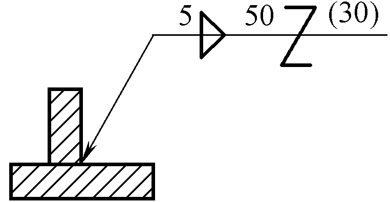
3 Collective Annotation In the same drawing, when several welds have the same bevel size and weld symbols, collective annotation can be used. 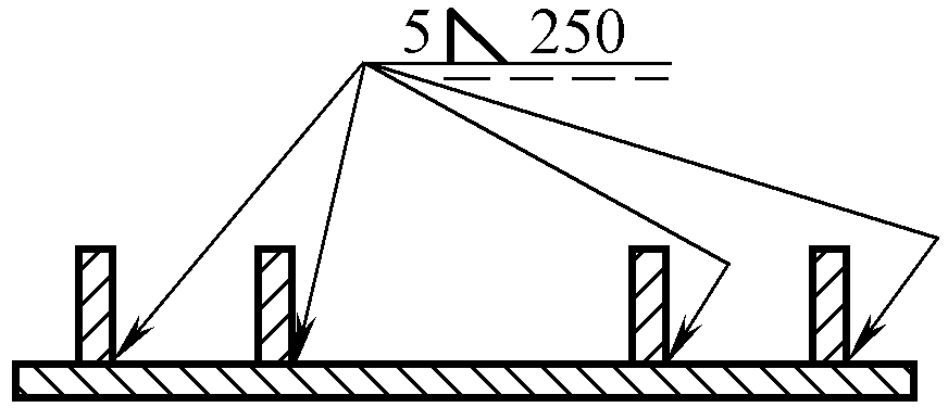
4 Annotation of Weld Quantity In the same drawing, when several welds are in the same position within a joint, simplification can be achieved by annotating the same weld quantity at the end of the weld symbol. However, other types of welds still need to be annotated separately. 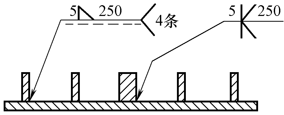
5 Simplified Code Annotation To simplify the annotation method or when the annotation location is limited, simplified weld codes can be annotated. However, the meanings of these simplified codes must be explained either below the drawing or near the title bar. When simplified codes are used, the codes and symbols explained below the drawing or near the title bar should be 1.4 times the size of those annotated on the drawing. 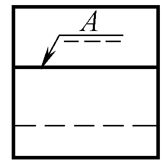
6 Omission of Reference Line or Weld Length Annotation In cases where it does not lead to misunderstanding, and when the arrow line points to the weld while there are no weld requirements on the non-arrow side, omitting the reference line (dashed line) on the non-arrow side is allowed. When the start and end positions of the weld length are clear (as determined by the dimensions of the components, etc.), omitting the weld length in the weld symbol is permitted. 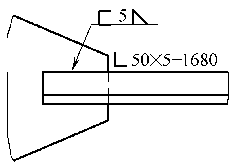
Note:
1. The positioning dimensions of the weld location should comply with relevant regulations.
2. When all the welds on the same drawing use the same welding method, the code indicating the welding method at the tail of the weld symbol can be omitted and not marked, but it must be stated in the technical requirements or other technical documents that “all welds use … welding” etc.; when most of the welding methods are the same, it can also be stated in the technical requirements or other technical documents that “except for the welding methods indicated in the drawing, the rest of the welds use … welding” etc.
3. When all the welds in the same drawing are the same and their positions are clearly indicated by the pictorial method, they can be uniformly indicated by symbols in the technical requirements or described in text; when some of the welds are the same, the same method can be used for representation, but the remaining welds should be clearly marked in the drawing.
Table 2-22 Welding and related process method codes (excerpted from GB/T5185—2005)Code Welding Method 1 Arc Welding 101 Metal Arc Welding 11 Gasless Arc Welding 111 Shielded Metal Arc Welding 112 Gravity Welding 114 Self-Shielded Flux-Cored Arc Welding 12 Submerged Arc Welding 121 Single Wire Submerged Arc Welding 121 Electroslag Submerged Arc Welding 123 Multi-Wire Submerged Arc Welding 124 Metal Powder Added Submerged Arc Welding 125 Flux-Cored Submerged Arc Welding 13 Gas Shielded Metal Arc Welding 131 Metal Inert Gas Welding (MIG) 135 Metal Active Gas Welding (MAG) 156 Non-Inert Gas Shielded Flux-Cored Arc Welding 137 Inert Gas Shielded Flux-Cored Arc Welding 14 Non-Consumable Electrode Gas Shielded Arc Welding 141 Tungsten Inert Gas Welding (TIG) 15 Plasma Arc Welding 151 Plasma Arc MIG Welding 152 Plasma Arc Powder Surfacing 18 Other Arc Welding Methods 185 Magnetic Arc Butt Welding 2 Resistance Welding 21 Spot Welding 211 Single-Sided Spot Welding 212 Double-Sided Spot Welding 22 Seam Welding 221 Lap Seam Welding 222 Flat Seam Welding 225 Thin Film Butt Seam Welding 226 Band Seam Welding 23 Projection Welding 231 Single-Sided Projection Welding 232 Double-Sided Projection Welding 24 Flash Welding 241 Preheated Flash Welding 242 Non-Preheated Flash Welding 25 Resistance Butt Welding 29 Other Resistance Welding Methods 291 High-Frequency Resistance Welding 3 Gas Welding 31 Oxy-Fuel Welding 311 Oxyacetylene Welding 312 Oxypropane Welding 313 Oxyhydrogen Welding 4 Pressure Welding 41 Ultrasonic Welding 42 Friction Welding 44 High Energy Rate Welding 45 Diffusion Welding 47 Pneumatic Welding 48 Cold Pressure Welding 5 High Energy Beam Welding 51 Electron Beam Welding 511 Vacuum Electron Beam Welding 512 Non-Vacuum Electron Beam Welding 52 Laser Welding 521 Solid-State Laser Welding 522 Gas Laser Welding 7 Other Welding Methods 71 Thermit Welding 72 Electroslag Welding 73 Gas Shielded Arc Spot Welding 74 Induction Welding 741 Induction Butt Welding 742 Induction Seam Welding 75 Light Radiation Welding 753 Infrared Welding 77 Impact Resistance Welding 78 Stud Welding 782 Resistance Stud Welding 783 Arc Stud Welding with Ceramic Ferrule or Shielding Gas 784 Short-Circuit Arc Stud Welding 785 Capacitor Discharge Stud Welding 786 Capacitor Discharge Stud Welding with Ignition Tip 787 Arc Stud Welding with Fusible Collar 788 Friction Stud Welding 8 Cutting and Gas Cutting 81 Flame Cutting 82 Arc Cutting 821 Air Arc Cutting 822 Oxy-Arc Cutting 83 Plasma Arc Cutting 84 Laser Cutting 86 Flame Gouging 87 Carbon Arc Gouging 871 Air Carbon Arc Gouging 872 Oxy Carbon Arc Gouging 88 Plasma Gouging 9 Brazing, Soldering, and Brazing 91 Hard Brazing 911 Infrared Hard Brazing 912 Flame Hard Brazing 913 Furnace Hard Brazing 914 Dip Hard Brazing 915 Salt Bath Hard Brazing 916 Induction Hard Brazing 918 Resistance Hard Brazing 919 Diffusion Hard Brazing 924 Vacuum Hard Brazing 93 Other Hard Brazing Methods 94 Soft Soldering 941 Infrared Soft Soldering 942 Flame Soft Soldering 943 Furnace Soft Soldering 944 Dip Soft Soldering 945 Salt Bath Soft Soldering 946 Induction Soft Soldering 947 Ultrasonic Soft Soldering 948 Resistance Soft Soldering 949 Diffusion Soft Soldering 951 Wave Soldering 952 Soldering Iron 954 Vacuum Soft Soldering 956 Drag Soldering 96 Other Soft Soldering Methods 97 Brazing 971 Gas Brazing 972 Arc Brazing
Note: The following welding methods have been removed in the new standard (GB/T5185—2005) from the old standard (GB/T5185—1985), these welding methods may still be used for special occasions, or appear in various documents from the past.
Table 2-23 Examples of welding method code notationAnnotation Example Meaning 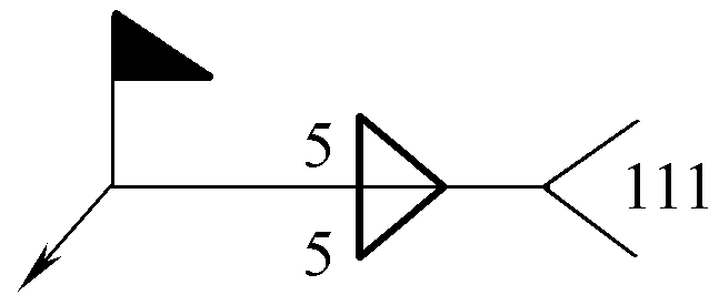
Symmetrical fillet welds with a leg size of 5mm are welded on the construction site using shielded metal arc welding. 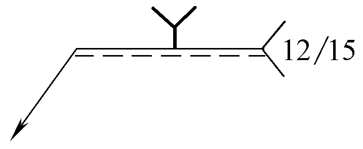
With a blunt-edged V-groove weld, first perform root welding with plasma arc welding, then cover the surface with submerged arc welding.