Oppervlaktekwaliteit verbeteren bij machinale bewerking: Sleuteltechnieken
De oppervlaktekwaliteit van machinale bewerking verwijst naar de oppervlaktegesteldheid van het onderdeel na machinale bewerking. De...
Welding auxiliary devices include a wide range of contents, in addition to welding lifting tools, lifting and transporting equipment, flux pads, flux recovery and delivery devices, and wire processing devices, beveling machines, root cleaning machines, grinding tools, ventilation equipment, and various protective equipment are all considered welding auxiliary equipment.
However, some auxiliary equipment is not exclusively for welding and will be discussed in other chapters, so only directly related equipment is introduced here.
In the production of welded structures, various plates, profiles, and welding components often need to be lifted and transported between different stations, and sometimes parts need to be flipped, positioned, dispersed, or concentrated according to technological requirements.
There is a significant amount of lifting work during production preparation, and using lifting tools that correspond to the cross-sectional shape of the workpiece plays an important role in improving transportation efficiency, saving labor time, reducing the intensity of bundling operations, and ensuring safe production.
Assembly welding lifting tools can be divided into mechanical lifting tools, magnetic lifting tools, and vacuum lifting tools according to their operating principles.
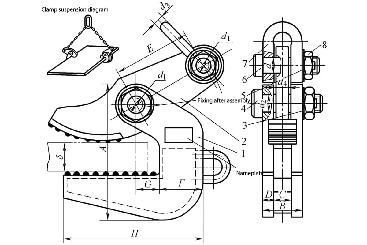
Figure 3-94 is a lifting device mainly used for horizontal lifting of plates. The devices are used in pairs and, depending on the specifications, each pair can lift between 1000 to 8000 kg. The entire device consists of lifting claws, pressure plates, pins, and lifting lugs. When used, if four devices are installed side by side on a longitudinal lifting beam through chains, it can be used for lifting longer, thinner plates, as well as cylindrical sections, boxes, and other structural components.
To ensure the safe use of the lifting device, an overload test should be conducted before use. The overload amount is set at 25% of the rated load and must last for 10 minutes. After unloading, the device must not have any residual deformation, micro-cracks, or cracks before it can be used.
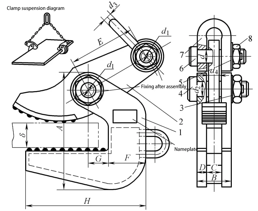
1—Lifting Claw
2—Pressure Plate
3, 5—Washer
4, 6—Pin
7—Lifting Lug
8—Nut
Figure 3-95 is a beam lifting device weighing 20 kg with a lifting capacity of 2000 kg. This type of device is often used for lifting I-beams, T-beams, and box beams. Its main feature is that the clamping jaws can automatically open and close under the weight of the lifting hook, allowing for easy grabbing and releasing of the workpiece, thus simplifying the lifting operation.
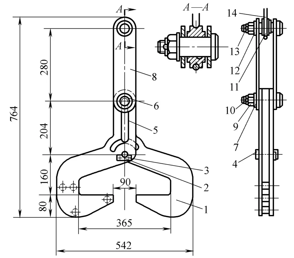
1—Right Claw
2—Stop Shaft Plate
3—Bolt
4, 6, 13—axis
5—Left Claw
7, 12—Washer
8—Connecting Plate
9—Nut
10—Pin
11—Pulley
14—Wire Rope
In magnetic lifting tools, there are permanent magnet type, electromagnetic type, and combined permanent-electromagnetic type lifting tools. The combined permanent-electromagnetic type lifting tool consists of a permanent magnet and an electromagnet, using the permanent magnet to attract the workpiece and the electromagnet to change polarity to enhance and weaken the magnetic force.
Figure 3-96 shows the structural forms of several combined permanent-electromagnetic type lifting tools.
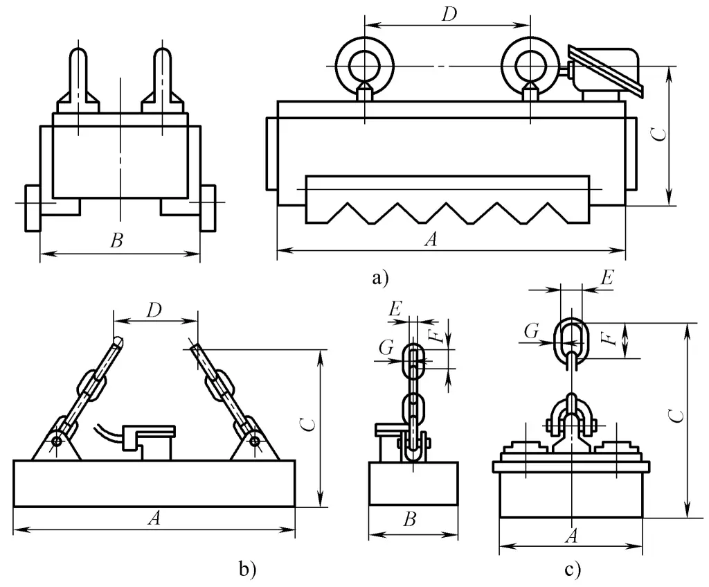
a) YMW12-5010T model
b) YMW24-15035L model
c) YMW04-30 model
The working principle of the combined permanent-electromagnetic lifting tool is: at the initial contact between the lifting tool and the workpiece, power the electromagnet and align its polarity with that of the permanent magnet to increase the adhesion force, firmly attaching the workpiece to the lifting tool, then turn off the current, switching to rely solely on the permanent magnet to attract the workpiece; when it is necessary to unload, reverse the current to the electromagnet to oppose the polarity of the permanent magnet, neutralizing the magnetic force of the permanent magnet to achieve rapid unloading.
The advantages of this type of lifting tool are: first, it is safe and reliable, there is no need to worry about workpiece falling due to power outages and other electrical faults causing personal and equipment accidents; second, it is energy-saving, with short power-on time and low electricity consumption, making it an energy-efficient safety lifting tool.
Note that magnetic lifting tools are only suitable for ferromagnetic materials and cannot be used to lift copper, aluminum, austenitic stainless steel, and other non-ferromagnetic materials.
Figure 3-97 is a vacuum lifting tool, consisting of suction cup 1, lighting lamp 2, lifting frame 3, piping 4, reversing valve 5, and distributor 6. During operation, it relies on a vacuum pump to vacuum the suction cup to attract the workpiece 7. Due to the small suction force, it is mainly used for lifting flat-surfaced, lightweight thin plates.
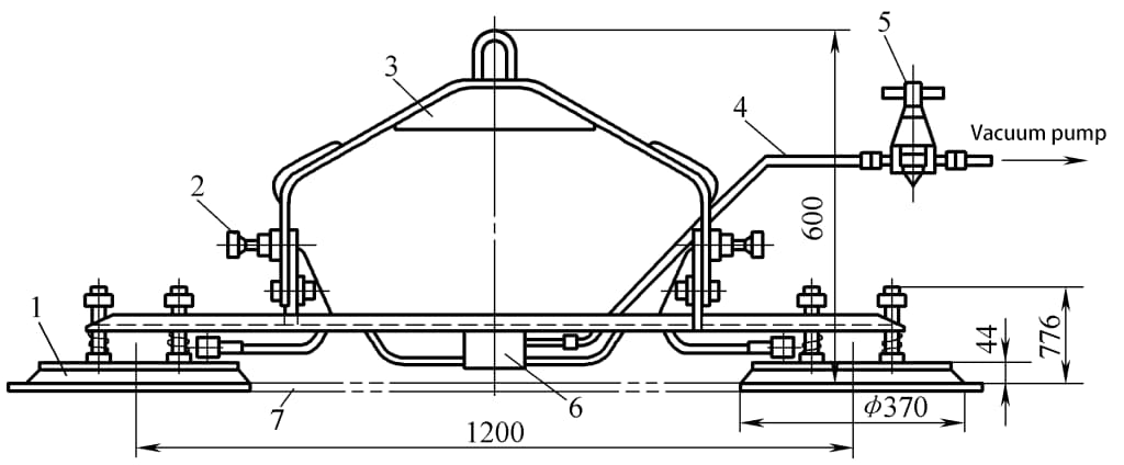
1—Suction Cup 2—Lighting Lamp 3—Lifting Frame 4—Piping 5—Reversing Valve 6—Distributor 7—Workpiece
In addition to the above-mentioned welding lifting tools, essential lifting and transport equipment in the welding structure production workshop includes ground transport equipment such as forklifts, electric transport vehicles, manual pallet trucks, electric flatbeds, and air cushion devices; lifting machinery equipment includes bridge cranes, gantry cranes, jib cranes, and suspension cranes; in mass production of products, conveyors are often needed to perform specialized production rhythmically.
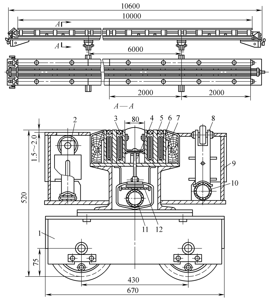
The forms of conveyance include suspension type, roller type, trolley type, stepping type, transmission belt type, cart type, and plate type, etc. Figure 3-98 is a schematic diagram of a single-rail suspension crane.
The track of this type of crane is fixed on the roof truss of the factory building, and the lifting traveling wheels are symmetrically arranged on the two limbs under the flange of the I-beam, and when the travel distance is less than 40m, power is generally supplied by a flexible cable, and the crane is operated by a worker on the ground using controller 2.
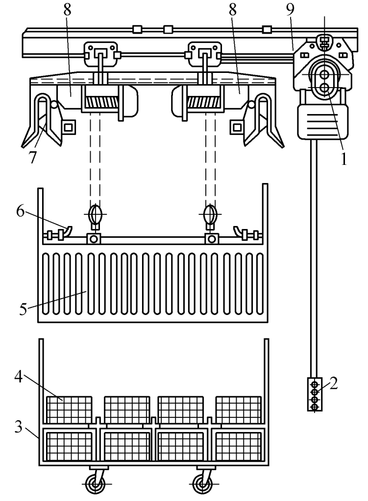
1—Mobile Electric Motor
2—Controller
3—Workpiece Trolley
4-Werkstuk
5—Cage
6—Pin
7—Fixed pin
8—Electric hoist
9—Track
The selection of lifting and transporting equipment in the welding workshop depends on the transport volume, transport distance and route, transport speed and degree of automation, weight of individual and structural components, transmission mode, and equipment productivity.
During welding, porosity is often caused by oil and rust, so it is necessary to remove anti-embroidery oil and rust from the welding wire before welding for various automatic welding methods. To improve the efficiency of rust and oil removal and reduce labor intensity, there are specialized equipment manufacturers in China that produce descaling machines.
The flux pad, also known as the weld seam forming device, uses a certain thickness of flux layer as a backing device for the back of the weld seam during booglassen onder poederdek to prevent burn-through or to form the backside. There are many structural forms of flux pads; some are manufactured by the production units themselves, while others are produced and supplied by professional factories.
(1) Rubber membrane type flux pad
As shown in Figure 3-99, when compressed air is introduced into chamber 5, the rubber diaphragm 3 bulges upwards, pushing the flux 1 to the back of the weldment to support it. The advantage of this flux pad is its simple structure and convenience of use.
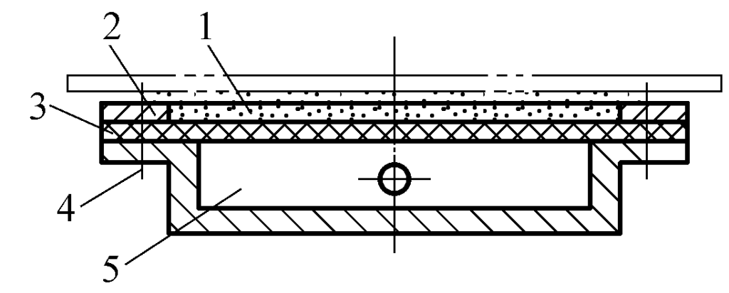
1—Flux
2—Cover Plate
3—Rubber Diaphragm
4—Bolt
5—Chamber
Its working part has a width of 300mm and a length of 2m. Excessive length can cause uneven pressure distribution on the rubber diaphragm, resulting in insufficient pressure at the end of the flux pad, which fails to support the molten pool, causing the molten iron to flow downwards and burn through. This type of flux pad is commonly used for welding long longitudinal seams.
(2) Hose Type Longitudinal Seam Flux Pad
As shown in Figure 3-100, during operation, the flux groove is first supported under the weld seam by the cylinder, and when compressed air inflates the hose 3, it presses the flux 1 against the weldment, making it tightly adhere to the back of the weld seam. The advantage of this type of flux pad is that it provides even pressure distribution, allows the back of the weld seam to be shaped, and is suitable for welding long longitudinal seams.
1—Flux
2—Canvas
3—Inflatable Hose
4—Cylinder
5—Flux Groove
The hose type flux pad is often used in combination with an electromagnetic clamping mechanism to form a specialized welding fixture for flat plate assembly. Figure 3-101 shows a fully functional and laterally movable electromagnetic hose type splicing device. This device can be used for splicing large flat plates, such as before rolling the tank bodies of railway oil tank cars, splicing ship decks, and bridge panels.
1—Trolley
2, 8—Support Roller
3—Flux Canvas Trough
4—Push Rod
5—Electromagnet Core
6—Electromagnetic Coil
7—Coil Casing
9—Cross Beam
10, 11, 12—Hoses (ф50 to ф65mm)
The weldable longitudinal seam length reaches 10m. The entire device is supported by two trolleys, which can move laterally along a 6m gauge steel rail to accommodate the welding of longitudinal seams at different positions.
The lateral adjustment of the weld seam is ensured by the trolley; when the support rollers 2, 8 are raised by the compressed air entering the hose 10, the flat steel plate can be appropriately adjusted longitudinally and laterally; appropriate adjustment of the seam position; after the seam position is determined, it is fixed with an electromagnet (suction not less than 20kN/m 2 ), and compressed air is passed through hose 12 to press the flux onto the weldment, allowing for longitudinal seam welding.
Figure 3-102 shows a hose-type flux pad used for welding the internal longitudinal seam of a large diameter cylinder. Its characteristic is to use the hose 6 to inflate and press the groove body 5 towards the weldment, and then inflate the hose 3 to press the flux towards the weldment, ensuring sufficient pressure of the flux while preventing it from spilling.
1—Steel wheel
2—Trolley
3, 6—Hose
4—Canvas groove
5—Steel groove body
Common types include disc type and conveyor belt type.
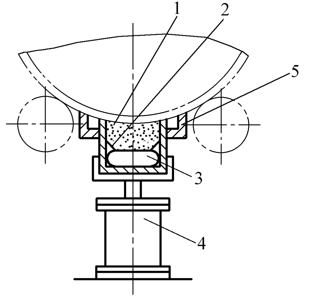
(1) Disc type circumferential seam flux pad
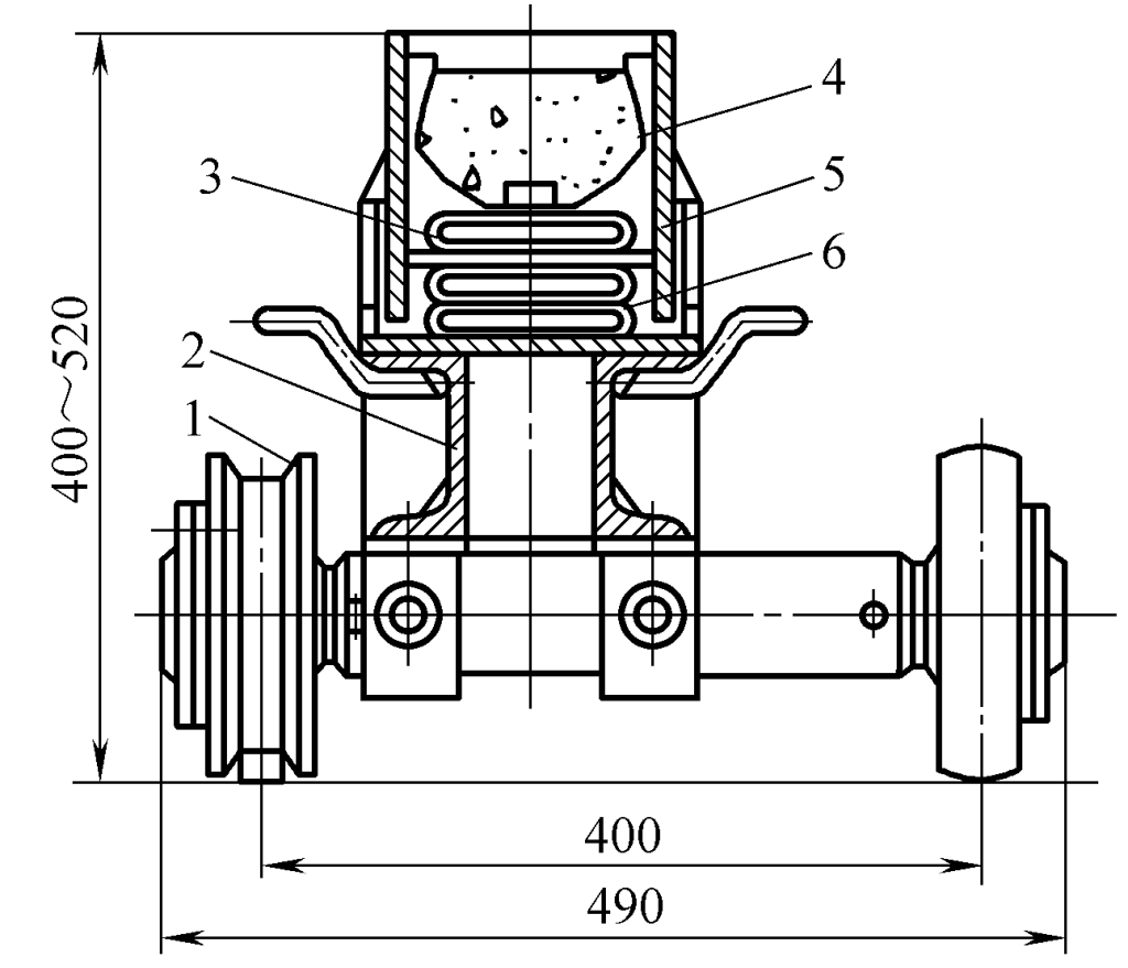
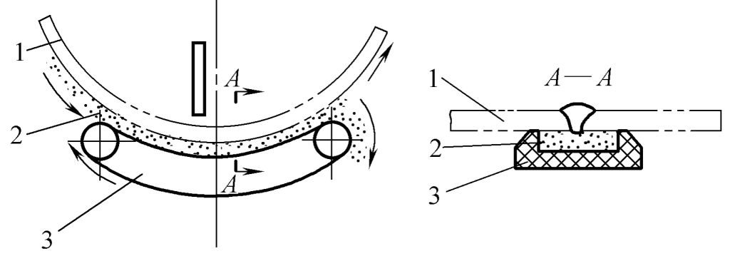
Its structure is shown in Figure 3-103. The working process involves aligning the flux-filled disc with the weld seam, pressing it towards the weldment with a cylinder 4, and during welding, the turntable rotates around its main axis with the rotation of the cylinder due to friction, continuously delivering flux to the weld path. This type of flux pad has a simple structure and is easy to use. The disadvantage is that the flux tends to scatter when the turntable rotates, requiring constant manual replenishment.
1—Rubber belt 2—Flux 3—Rolling bearing 4—Cylinder
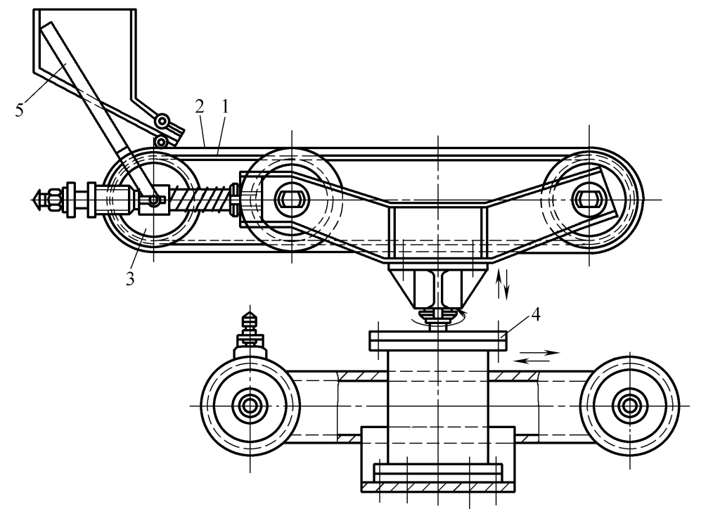
Figure 3-104 shows a ring groove type flux pad, the working principle is the same as described above, the difference is that the disc 3 is equipped with an elastic annular groove 6, filled with flux, pressed towards the weldment by the cylinder 4, and also driven to rotate by the workpiece.
1—Trolley
2—Shaft
3—Disc
4—Cylinder
5—Slot Holder
6—Ring Groove
(2) Belt Type Flux Pad
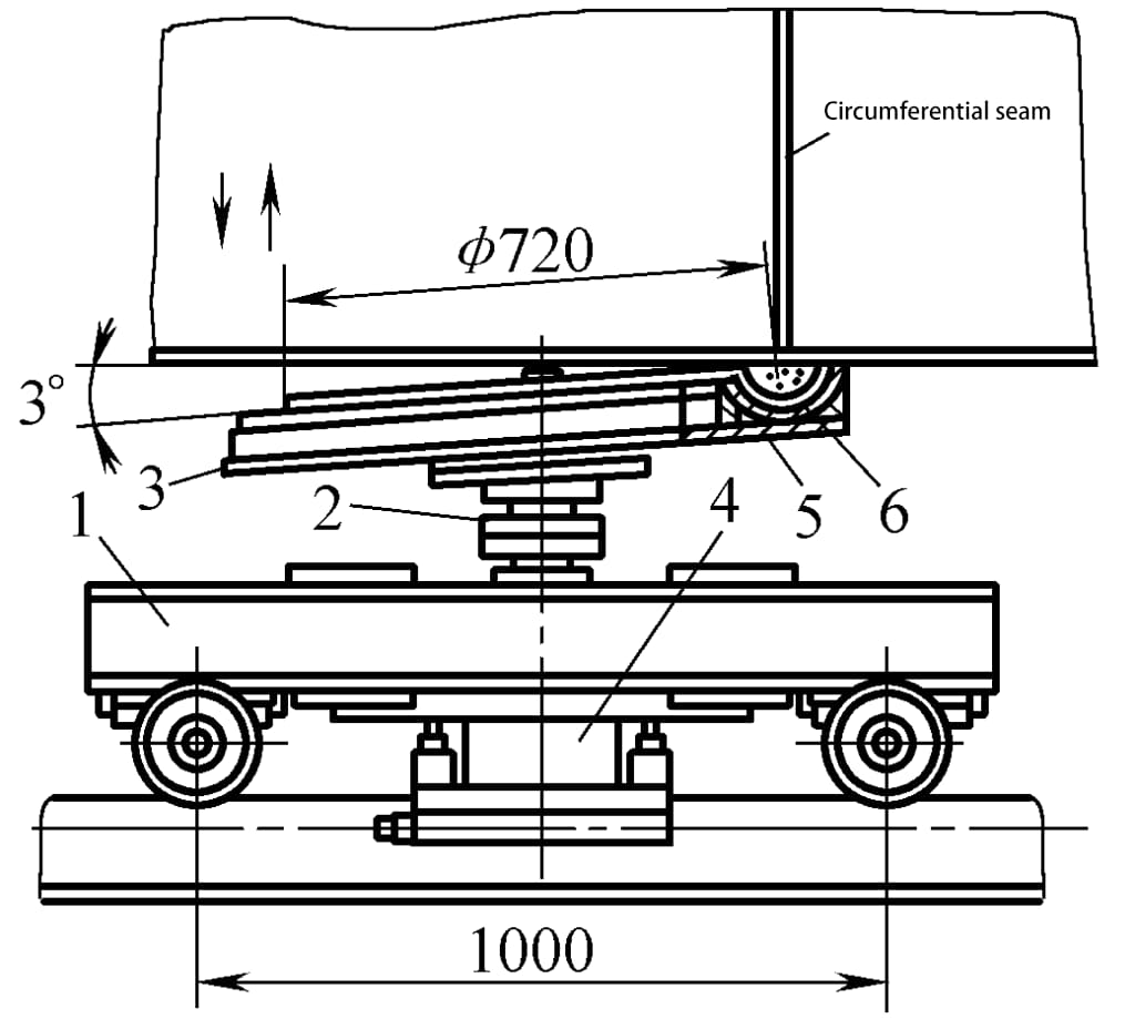
The working principle is shown in Figure 3-105, where the flux-filled conveyor belt presses against the workpiece under the action of gravity or a cylinder, and is driven to rotate by the workpiece. Figure 3-106 shows the structure of an actual belt-type flux pad in use. The process involves the flux-filled conveyor belt pressing towards the workpiece under the action of cylinder 4, and as the cylindrical body of the workpiece rotates, it drives the belt to rotate.
1—Cylinder
2—Flux
3—Conveyor Belt
Its features include: sturdy structure, reliable use, convenient maintenance, uniform flux thickness, appropriate stress, flux not easily broken, easy control of granularity, good air permeability, but the flux tends to fall to the ground, limited mobility, not suitable for narrow spaces, requires manual addition of flux.
1—Belt
2—Flux
3—Tension Structure
4—Cylinder
5—Worm Gear
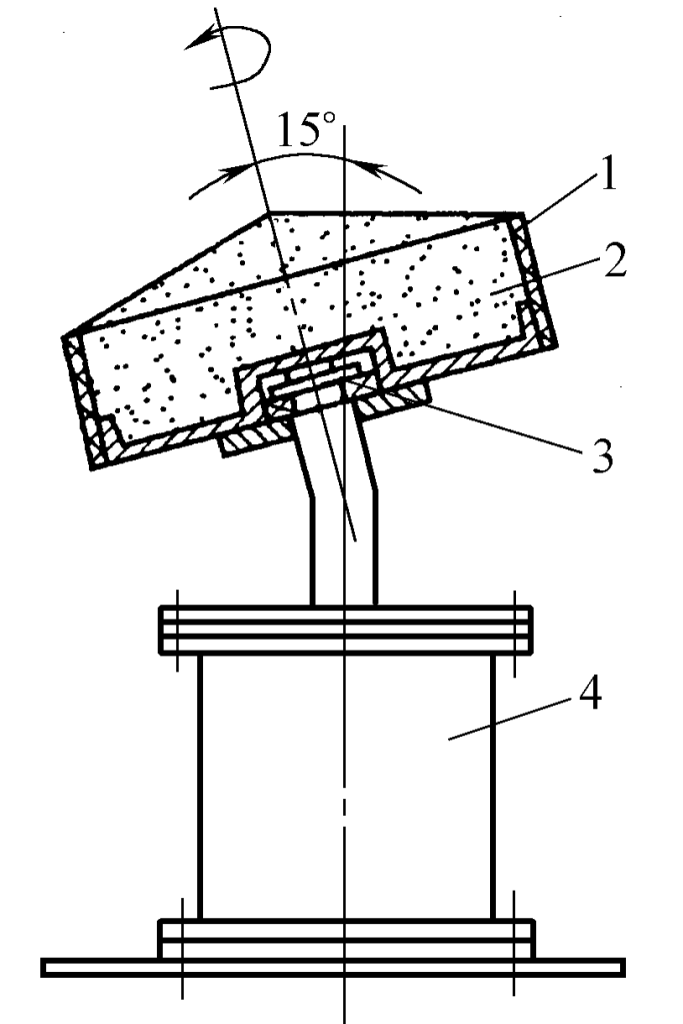
Soft pads made of thermosetting resin and quartz sand are attached to the back of the weld with adhesive tape or pressed against the weldment with magnetic clamps, as shown in Figure 3-107. Due to their small size, they are suitable for straight and curved welds (including circumferential seams) in narrow areas.
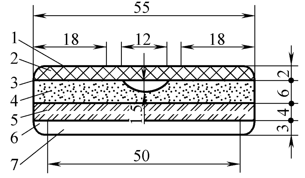
1—Plastic-faced isolation paper
2—Double-sided adhesive tape
3—Glass fiber tape
4—Thermosetting resin quartz sand pad
5—Asbestos mud board pad
6—Heat shrink film
7—Corrugated paper lining
When the groove gap is within 3mm and the blunt edge is within 2mm, single-sided welding and double-sided formation can be ensured. The disadvantage is that metal particles with a certain alloy composition need to be filled in the groove during use, and the manufacturing process of the soft pad is complex.
It can be divided into two types: horizontal and vertical:
(1) Horizontal Spiral Propeller Type Flux Pad
It mainly uses the spiral propeller to push the flux towards the surface of the weldment and allows the flux to circulate automatically. During use, the lifting transmission mechanism can be utilized to adjust the height of the flux pad to ensure good contact with the surface of the weldment.
(2) Vertical Spiral Propeller Type Flux Pad
Its working principle is the same as the horizontal type, the difference being that the vertical spiral propeller is installed vertically, and the unmelted flux returns by its own weight. Its advantages include flexible movement, reducing the labor of workers shoveling flux, and maintaining appropriate contact pressure between the flux pad and the surface of the weldment. The disadvantage is that the structure is more complex, the transmission mechanism requires good sealing, and the flux is prone to breakage.
The structure of the thermosetting flux pad is shown in Figure 3-108. The thermosetting flux pad is about 600mm long and is fixed to the bottom of the weldment using magnetic fixtures. This type of pad is highly flexible, has good conformity, is safe and convenient, and easy to store.
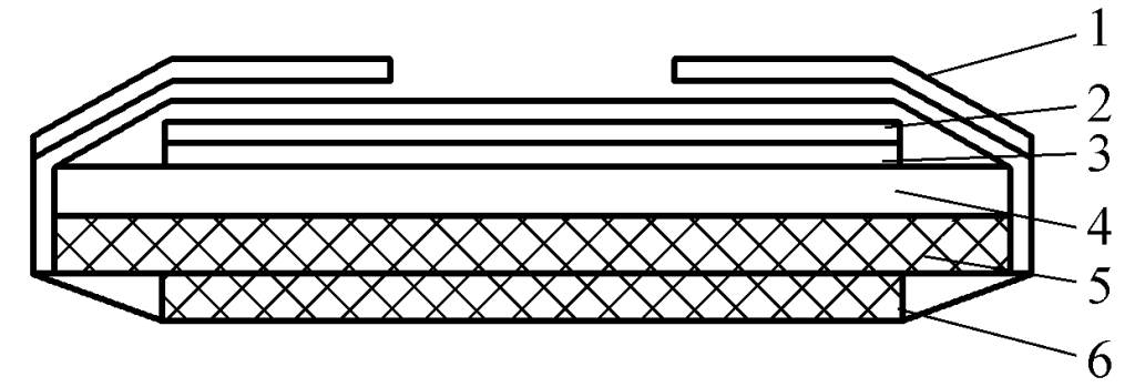
1—Double-sided Adhesive Tape
2—Heat shrink film
3—Glass fiber cloth
4—Thermosetting flux
5—Asbestos cloth
6—Elastic pad
During the submerged arc welding process, it is necessary to continuously deliver flux to the welding area, and the un-melted flux after welding must be recovered and reused, thus requiring a flux delivery and recovery device.
According to production needs, the delivery and recovery of flux can be combined to form a circulation system, working simultaneously during welding, allowing the flux to be continuously recovered and then sent back for use. Alternatively, the two can be separated, meaning the flux delivery device and recovery device can work independently.
(1) Fixed flux circulation system
Figure 3-109 is a flux circulation system for a spiral pipe welding machine. The flux falls by gravity, and after being recovered by the bucket elevator 2, it is re-fed into the flux hopper 1 for continued use.
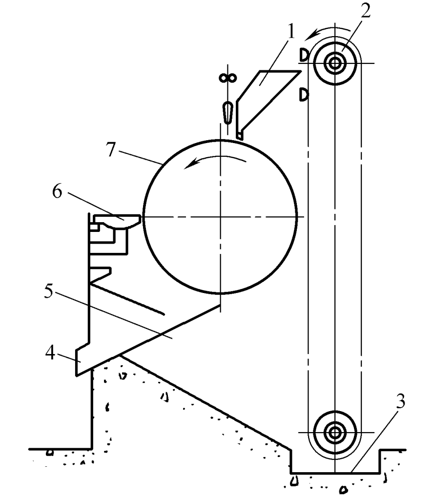
1—Flux Hopper
2—Bucket Elevator
3—Flux Tank
4—Slag Outlet
5—Screen
6—Slag Removal Knife
7—Pipe to be welded (Spiral Pipe)
(2) Mobile Flux Circulation System
Figure 3-110 is a mobile flux circulation system, where the flux delivery and recovery device is installed on the welding head 5, moving along with the welding cart (or the telescopic arm of the welding manipulator). During operation, the flux is transported from the storage tank 3 through the conduit 4 to the front of the arc, and the unfused flux is recovered by the suction tube 1 about 300mm from the arc, then it enters back into the storage tank 3 through the conduit 2.
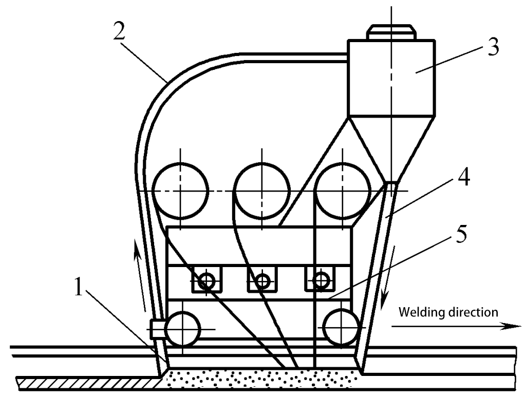
1—Suction tube
2, 4—Conduit
3—Storage tank
5—Head (cart)
Most flux recovery devices use a suction method to draw the flux into the storage tank. The power sources for these devices are electric and pneumatic, with pneumatic being the most commonly used.
(1) Electric Suction Type Flux Recovery Device
The electric flux recovery device shown in Figure 3-111 utilizes an electric centrifugal fan to create a negative pressure inside the flux tank, drawing the flux into the tank with the airflow. The advantage is that it has strong suction power, suitable for long-distance recovery, and the flux does not come into contact with compressed air, thus not getting contaminated.
However, the flux may break, and the inner walls of the equipment may wear. If used for conveying at the same time, the conveying distance is short due to the negative pressure inside the tank.
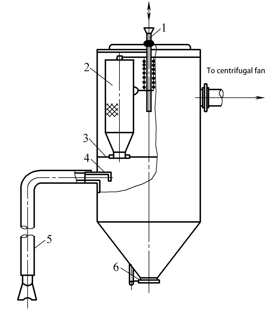
1—Vibrating rod
2—Dust filter bag
3—Partition
4—Heat-resistant rubber baffle
5—Hose and nozzle
6—Flux outlet
(2) Pneumatic suction flux recovery device
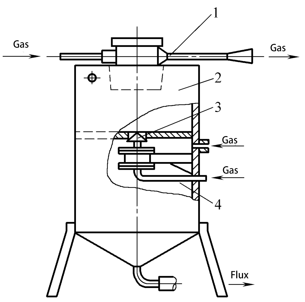
As shown in Figure 3-112, it is a pneumatic flux recovery device. It uses the airflow ejected from the upper Laval nozzle to create a negative pressure inside the sealed flux tank, and the flux is carried into the storage tank by the airflow.
1—Copper mesh filter
2—Flux suction tube
3—Compressed air inlet
4—Injection tube
5—Nozzle
6—Isothermal tube
7—Expansion tube
8—Compressed air outlet
9—Release tube
The flux does not come into contact with compressed air and is not contaminated. However, the flux also experiences fragmentation and causes wear on the inner walls. This device has a simple structure, complete flux recovery, and the use of factory compressed air is very convenient. If used for conveying at the same time, due to the negative pressure conveying and short distance, it is suitable to be directly mounted on the welding machine.
(3) Mixed type flux recovery device
As shown in Figure 3-113, the mixed type flux recovery device consists of a suction-type recycler and a positive pressure conveyor. When the pneumatic valve 3 is opened, the flux in the recycler falls into the conveyor. Thus, the flux can be continuously recovered and periodically conveyed, achieving a unified recovery and conveying. Since the tank is under positive pressure conveying, the conveying is reliable, suitable for longer distances, and more appropriate for fixed situations.
1—Injector
2—Reclaimer
3—Air Valve
4—Conveyor
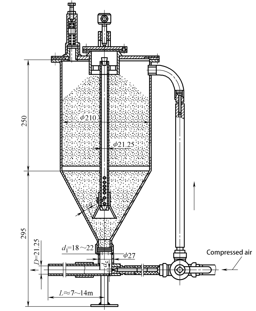
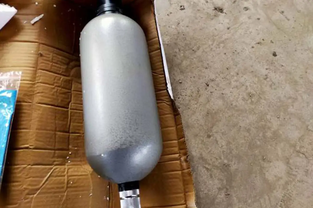
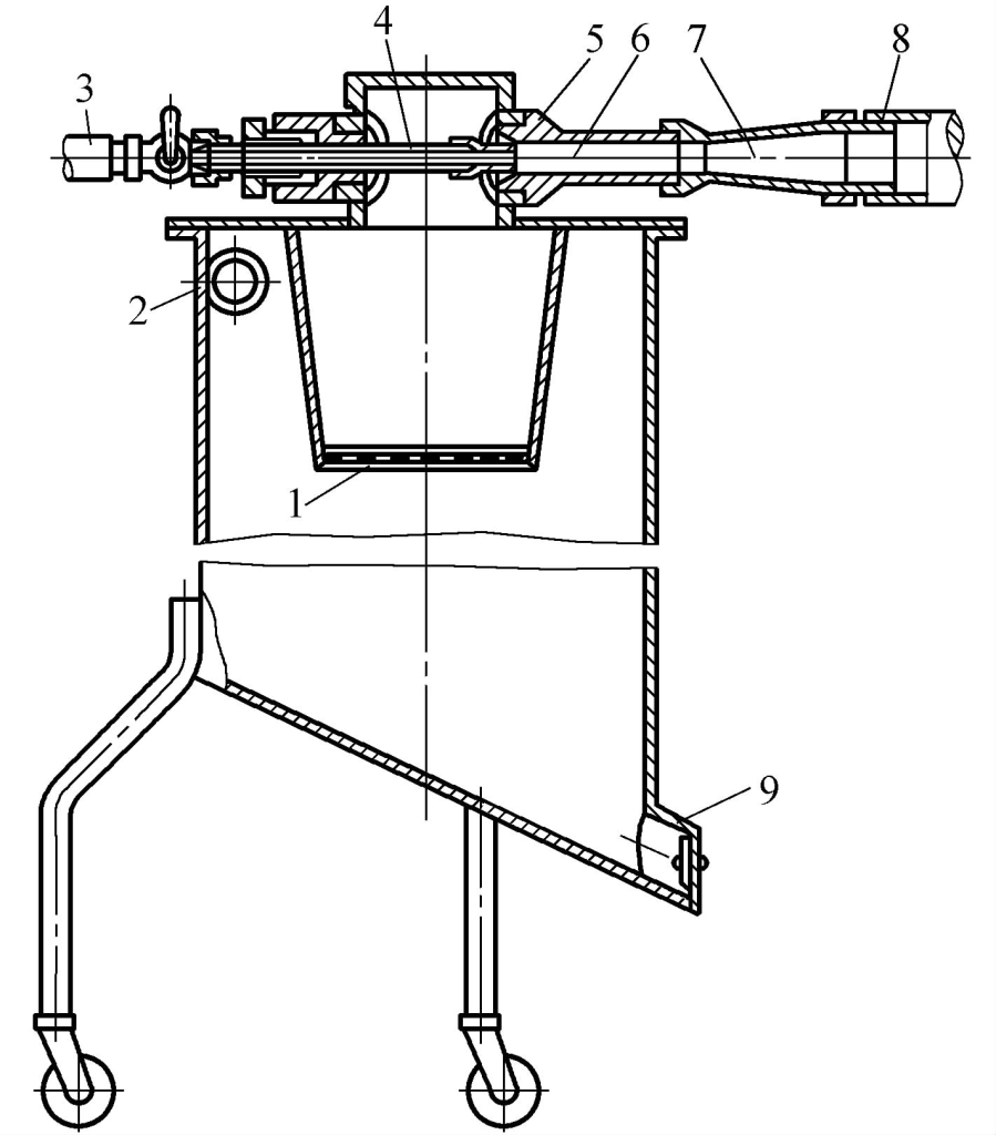
The flux delivery device refers to a specialized device for long-distance transportation. Its working principle is shown in Figure 3-114. When compressed air enters the upper part of the conveyor through the intake pipe and pressure reducing valve 1, it pressurizes the flux in the flux cylinder and causes the flux to flow along with the compressed air through the pipeline to the flux funnel of the welding machine, or directly to the semi-automatic welding gun. At this point, the flux falls, and the air escapes from the upper outlet.
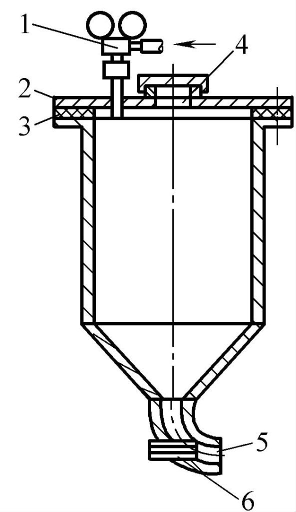
1—Intake Pipe and Pressure Reducing Valve
2—Flux Cylinder Cover
3—Gasket
4—Flux Inlet
5—Flux Outlet
6—Pipe End Booster
To make the flux delivery more reliable, a booster can be installed at the outlet of the flux cylinder. When the delivery distance is long, a booster can also be installed on the delivery pipeline to overcome pipe friction.
When using compressed air to transport flux, it is necessary to install an air-water separator to eliminate water and oil in the compressed air.
Figure 3-115 shows the structure of a typical flux delivery device. When the outlet pipe diameter D=21.25mm, take a=16mm, d 1 =22mm, d c =8mm, suitable for coarser flux particles; when the flux particles are no larger than 2.5mm, D can be reduced to 16mm; when less than 1.5mm, D can be 13mm, and other dimensions are correspondingly reduced.