How to Calculate Sheet Metal Weight: Essential Formulas
Ever wondered how to quickly calculate the weight of sheet metal? This article unveils a simple formula that takes the…
How do hydraulic systems store and release energy efficiently? The answer lies in accumulators, vital components that balance system pressure and store hydraulic energy. This article explores the different types of accumulators—gas-charged and spring-loaded—their working principles, and their structural variations. By reading, you’ll gain insight into how these devices enhance system stability, absorb pressure shocks, and ensure reliable operation in hydraulic mechanisms.

In hydraulic systems, an accumulator is a device that uses the principle of force balance to change the volume of working oil, thereby storing and releasing hydraulic energy.
As shown in Figure 1, the accumulator is basically composed of four parts: the shell, the piston, high-purity nitrogen gas (or possibly a spring) above the piston, and the working oil connected to the system below the piston. The working process can be divided into two stages: energy storage and release.
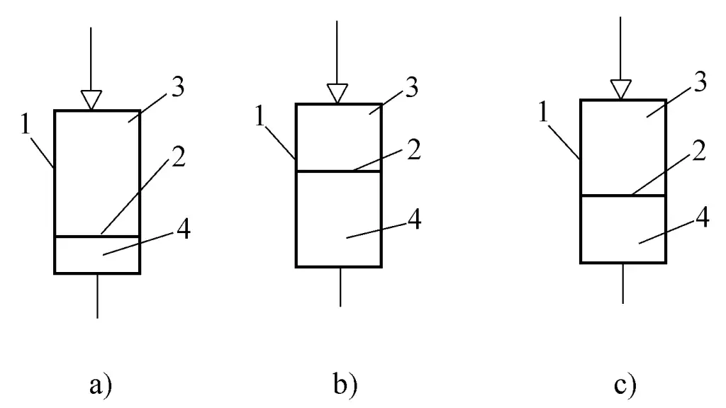
1—Shell
2—Piston
3—High-purity nitrogen gas (or possibly a spring)
4—Working oil
As shown in Figure 1a, the accumulator is in a pre-energy storage state, where the working oil and high-purity nitrogen gas (or spring force) above and below the piston are in a balanced state. The high-purity nitrogen gas is in a pre-charged state (or the spring is in a pre-compressed state), and the volume of the working oil is V1 .
When the system pressure increases, the pressure of the working oil also increases, pushing the piston upward, and the working oil in the system enters the accumulator (the volume increases to V2 ) until a balanced state is reached, as shown in Figure 1b.
At this time, the volume of working oil (V2 – V1 ) enters the accumulator for storage. This stage is called the energy storage stage. During this stage, the accumulator stores a certain pressure and volume (V2 – V1 ) of working oil.
When the hydraulic system performs opening or closing operations, the system pressure is lower than the pressure of the working oil in the accumulator. Under the pressure of the gas (or spring force), the piston is pushed downward, and the working oil is discharged into the system until a balanced state is reached, as shown in Figure 1c. This stage is called the release stage. During this stage, part of the working oil stored in the energy storage stage is discharged into the system.
From the above, it can be seen that as long as there is a change in system pressure, the pressure of the working oil in the accumulator changes accordingly. According to the principle of force balance, the piston moves, and the volume of the working oil changes accordingly. This repeated energy storage and release achieves the purpose of the accumulator.
In hydraulic systems, accumulators are generally divided into gas-charged and spring-loaded types based on the substance acting on the working oil. Each type of accumulator has different forms based on its structure. The specific classifications are as follows:
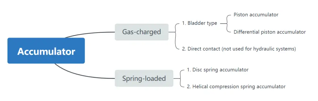
The working principle of the gas-charged accumulator is to use high-purity nitrogen gas pre-charged in the accumulator to balance with the pressure oil charged into the accumulator by the hydraulic pump. When the system needs oil, the oil is discharged under the pressure of the gas. Gas-charged accumulators are divided into isolated and direct contact types.
Isolated accumulator: An isolated accumulator refers to an accumulator where there is a separator between the gas and the liquid inside the accumulator, preventing the gas from easily mixing with the liquid. This type of accumulator effectively utilizes the compressibility of the gas and is therefore widely used. Based on the form of the separator, it is further divided into flexible and non-flexible accumulators.
Flexible accumulators, such as bladder accumulators, are used in hydraulic systems, while non-flexible accumulators, such as piston and differential piston accumulators, are most commonly used in hydraulic systems.
The working principle of the bladder accumulator is based on Boyle’s law, and its typical structure is shown in Figure 2.
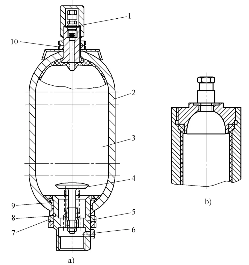
1—Inflation valve
2—Shell
3—Bladder
4—Mushroom valve
5—Valve body assembly
6—Half-round clamp
7—Nut
8—Gasket
9—O-ring
10—Tightening nut
Before use, first fill the bladder 3 in the accumulator with nitrogen at a predetermined pressure, then use a hydraulic pump to fill the accumulator with oil. Under the action of the pressure oil, the mushroom valve 4 is pushed open, and the oil enters the container, compressing the bladder. When the pressure in the gas chamber and the oil chamber is equal, the bladder is in a balanced state, and the pressure in the accumulator is the pump pressure. When the system needs oil, the bladder expands under the action of gas pressure, gradually squeezing out the oil.
The advantages of this type of accumulator are: the gas chamber and the oil chamber are separated by a bladder, ensuring reliable sealing with no leakage between the two; the bladder has low inertia, is responsive, compact in structure, small in size, light in weight, easy to maintain, and is often used in hydraulic systems with small-volume bladder accumulators to absorb pressure pulsations or as buffers. It is also used in situations with low operating power and pressure to store energy in hydraulic systems.
The typical structure of a bladder accumulator is shown in Figure 2a. It consists of an inflation valve 1, a shell 2, a bladder 3, and a mushroom valve 4. The shell 2 is a pressure vessel with an opening at the top to accommodate the inflation valve 1. The fully enclosed bladder 3, made of synthetic rubber, is pressed against the valve stem, forming a sealed space.
After the bladder is inserted through the opening at the lower end of the shell, it is fixed to the upper part of the shell with a tightening nut 10. The valve body assembly 5 is clamped by a pair of half-round clamps 6 installed inside the opening of the shell, securing the shoulder of the valve body 5. It is installed at the lower part of the shell, and with the O-ring 9 and gasket 8, it is tightened with a nut 7.
The function of the mushroom valve 4 in the valve body assembly 5 is to prevent the bladder from expanding out of the shell when all the oil is discharged. This type of accumulator has an O-ring at the opening of the shell. When the internal pressure of the shell increases to the burst pressure, the opening of the shell expands first, causing the O-ring to be squeezed out, safely releasing the oil pressure.
The above describes the bladder accumulator with type A structure. This type of accumulator is inconvenient for bladder replacement. Therefore, the top of the shell and bladder is designed with an “open-top” structure, as shown in Figure 2b, referred to as the type B bladder accumulator.
The piston accumulator uses a piston to separate the oil and nitrogen, as shown in Figure 3. The advantages of this type of accumulator are: simple structure and long service life. However, the piston has high inertia and sealing friction resistance, resulting in poor responsiveness; it requires high machining precision and is difficult to seal, making it unsuitable for absorbing pulsations and hydraulic shocks.
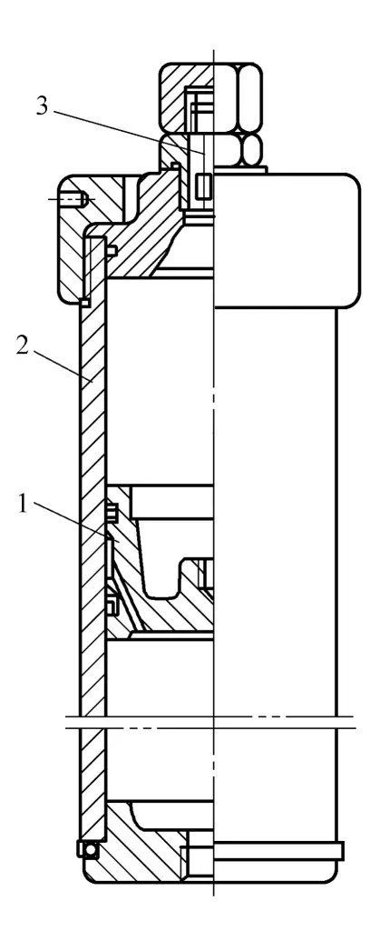
1—Piston
2—Cylinder
3—Inflation cylinder
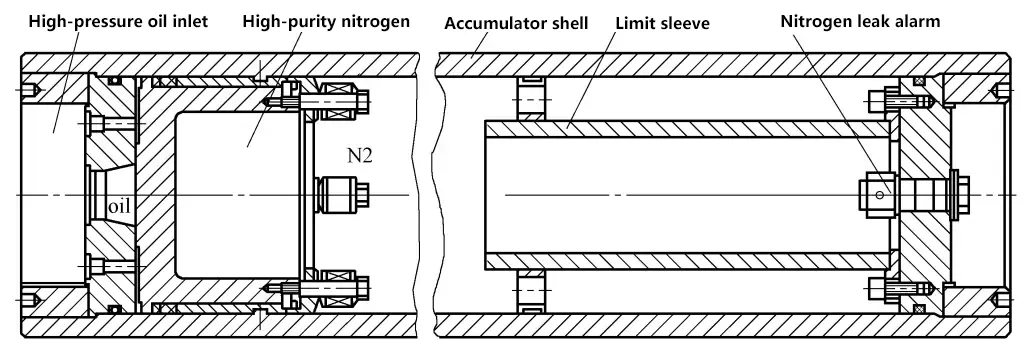
In hydraulic systems, this structure is commonly used for energy storage. The commonly used piston accumulator for energy storage in hydraulic systems is shown in Figure 4.
This type of accumulator uses the force of a spring acting on the piston to balance the pressure of the oil, storing pressure energy. The pressure generated by the accumulator depends on the stiffness and compression of the spring.
Common types include helical compression springs and disc springs. The helical compression spring accumulator is shown in Figure 5. This type of accumulator has a simple structure and relatively responsive, with its service life depending on the spring’s lifespan.
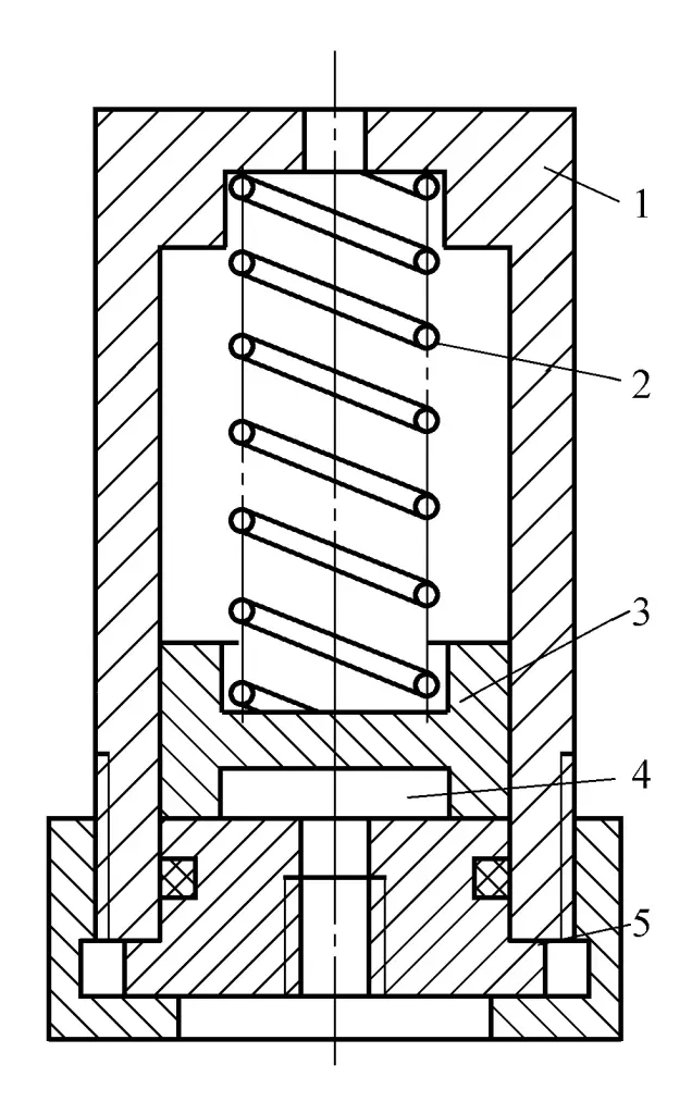
1—Shell
2—Spring
3—Piston
4—Oil chamber
5—Cover
It is used for energy storage and buffering in small-capacity, low-pressure, and low-cycle frequency systems, and is generally not used in hydraulic systems. In hydraulic systems, disc spring accumulators are commonly used, as shown in Figure 6.
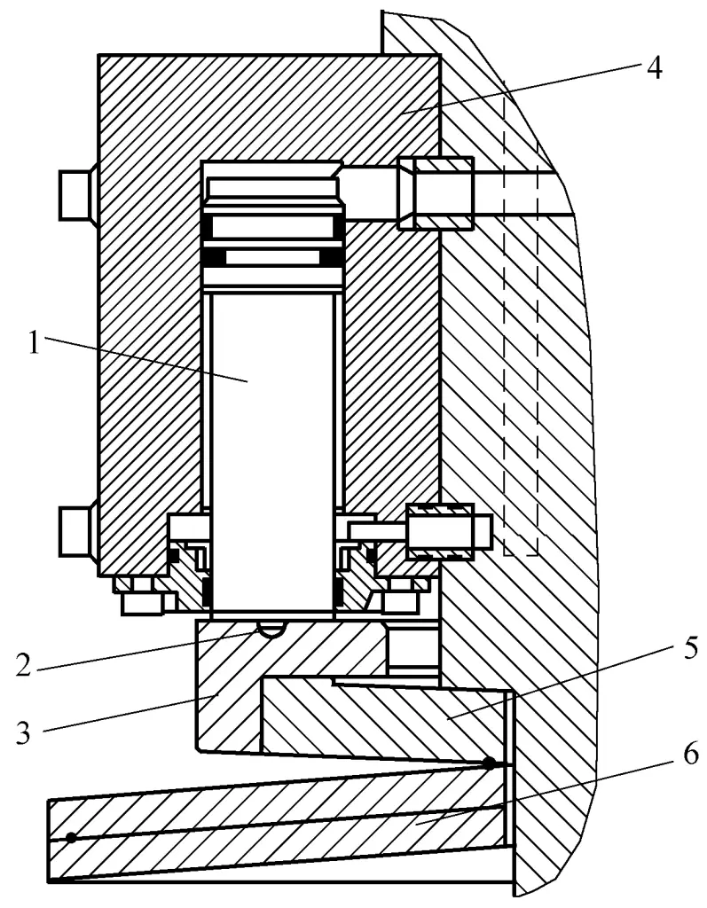
1—Energy Storage Piston
2—Positioning Hole
3—Support Ring
4—Housing
5—Support Disc Spring
6—Disc Spring Set
The accumulator is a device used to store the pressure energy of the hydraulic fluid, which can release this energy to perform useful work when needed. Its main functions in a hydraulic system are as follows:
The main use of the accumulator in hydraulic mechanisms. When the required flow rate varies greatly at different stages of a hydraulic system’s work cycle, an accumulator is often used in conjunction with a smaller pump to form the oil source. If the system requires a small flow rate, the accumulator stores the excess flow from the hydraulic pump; if the system requires a large flow rate for a short period, the accumulator releases the stored hydraulic fluid to supply oil to the system along with the hydraulic pump.
Additionally, when the hydraulic pump stops supplying oil to the system, the accumulator provides the stored pressure oil to the system to compensate for system leakage or maintain constant system pressure. It can also be used as an emergency energy source in case of hydraulic pump failure.
The secondary use of the accumulator in hydraulic mechanisms. In a hydraulic system, the accumulator is used to absorb shock pressures generated by sudden changes in fluid flow speed (such as when a directional valve suddenly shifts or a hydraulic cylinder load suddenly stops moving), thereby reducing the peak value of pressure shocks.
The flow pulsation of the hydraulic pump can cause uneven load movement speed and pressure pulsations. Therefore, systems that require relatively uniform load speed should install a corresponding accumulator at the pump outlet to improve the stability of system operation.