Measurement Tools: A Comprehensive Guide
Have you ever wondered how machinists achieve such precise measurements? In the world of mechanical engineering, accuracy is everything. This…
In this article, we’ll take a fascinating look at the advanced cutting tools used by today’s lathe operators. You’ll learn about the different types of tools, how they work, and the amazing capabilities they bring to the manufacturing process. Get ready to be amazed by the science and artistry that goes into every cut!
Proficiently mastering various advanced cutting tools, such as mechanically clamped indexable tools, coated tools, diamond tools, cubic boron nitride tools, and ceramic tools, including their performance, types, and application ranges, as well as improvement methods for twist drills and sharpening of gang drills, is one of the essential skills that lathe operators must possess.
Indexable turning tools are a type of tool where inserts with several cutting edges and reasonable geometric parameters are mechanically clamped onto a tool holder (or tool body). Compared to brazed turning tools, indexable turning tools have the following advantages.
When the cutting edge is worn, there’s no need to resharpen the insert. Simply rotate the insert to a new cutting edge for continued use, thus reducing tool change and sharpening auxiliary time.
This avoids internal stresses and cracks caused by brazing, fully utilizing the original cutting performance of the insert material and improving tool life.
This is beneficial for promoting the application of coated materials, further improving cutting efficiency and tool life.
The groove dimensions are stable, chip breaking is reliable, which helps ensure processing quality.
This saves tool body material, facilitates tool standardization, and simplifies tool management work.
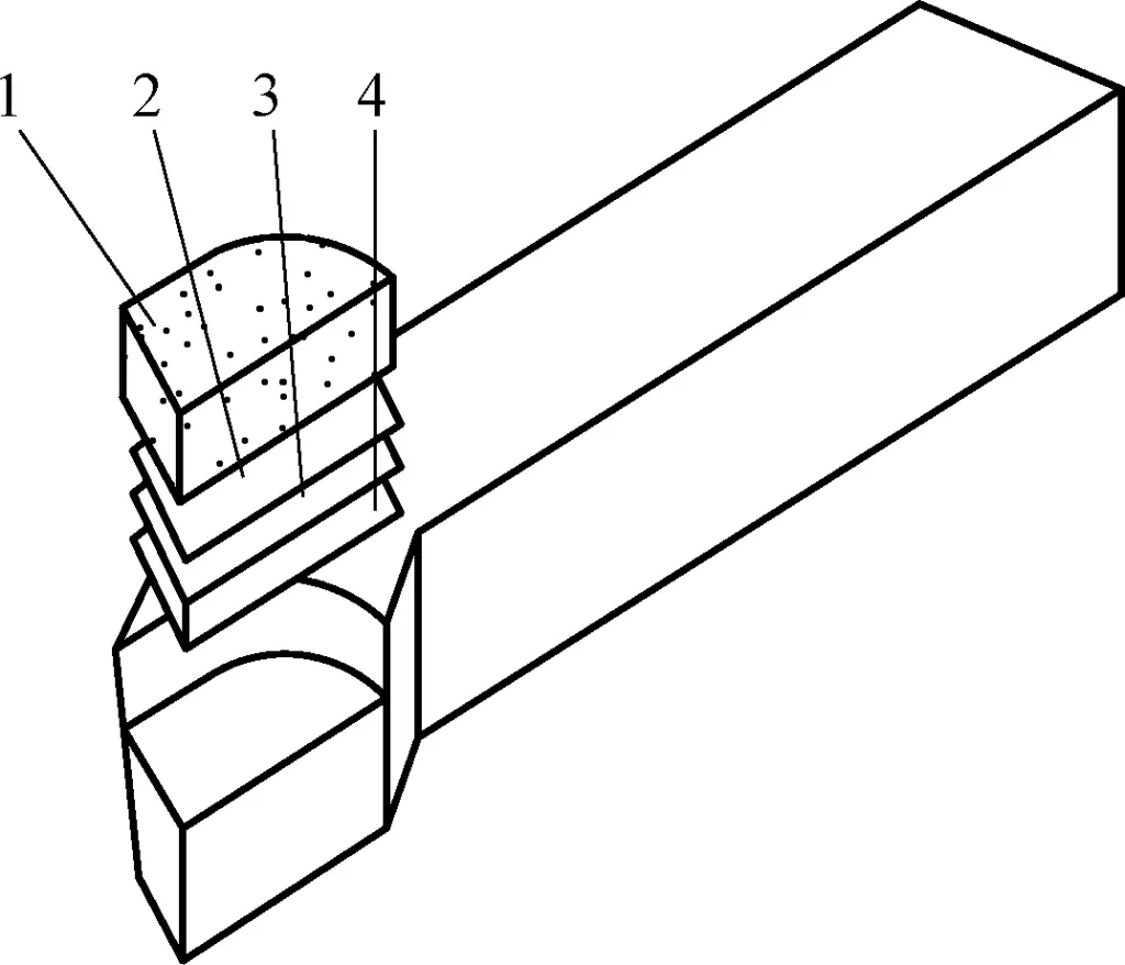
Indexable turning tools consist of a tool holder, clamping mechanism, insert, and shim, as shown in Figure 1.
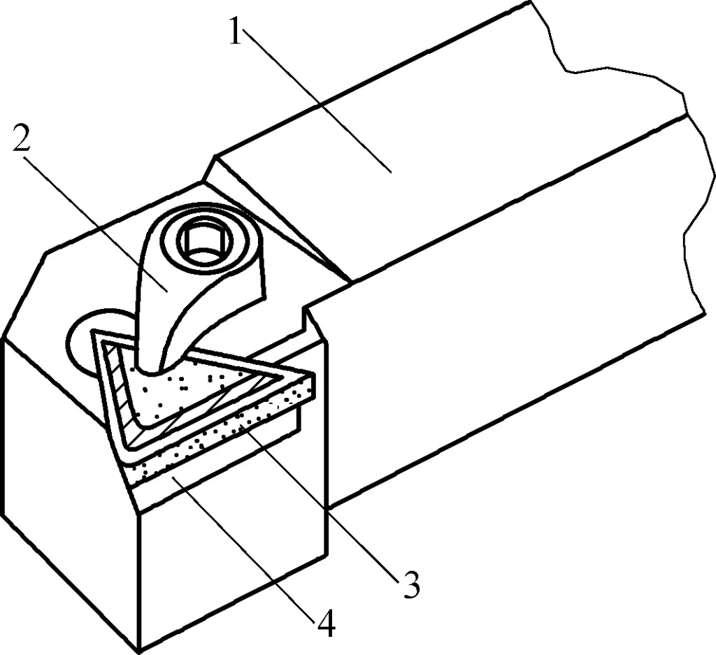
1—Tool holder
2—Clamping mechanism
3—Insert
4—Shim
Insert materials include carbide and ceramic. According to national standards, the model number of the insert is composed of ten positions arranged in a given order, representing the insert’s shape, normal clearance angle, precision grade, structural features, cutting edge length, insert thickness, nose radius, edge form, cutting direction, and chip breaker type and width.
For example:
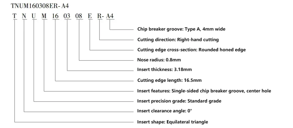
There are 17 types of insert shape codes. The most common ones are equilateral triangle (T), square (S), triangular with minor cutting edge (F), and convex trigon (W). There are 9 types of normal clearance angle codes, with the most widely used being type N with α₀ = 0°.
There are 11 types of insert precision grade codes, among which A, F, C, H, E, G, J, K, L belong to the precision grade, M belongs to the medium grade, and U is the most widely used general grade. For details on the meaning and method of expressing each letter or number in the indexable insert model number, refer to the standard GB/T 2076—2007.
The insert model should be selected based on processing conditions and workpiece material.
Used for clamping the insert and mounting on the tool post, the insert pocket on the tool holder is used to place and ensure the positioning of the insert. The main angles of the indexable turning tool are formed by installing the insert in an insert pocket with certain geometric angles. The geometric parameters of the insert pocket on the tool holder should be determined based on the angles of the selected insert. The tool holder material is 45 steel, with a hardness of 35~40HRC.
Using a shim makes it easy to adjust the position of the indexable turning tool tip; it protects the tool holder from damage during tool setting. During normal cutting, it prevents chips from scratching the tool holder. Shim materials are selected from GCr15, YG8, or W18Cr4V.
The insert positioning and clamping mechanism should meet the following requirements:
The insert positioning form should strive to minimize the change in tool tip position after insert rotation. There are four common positioning forms:
1) Positioning using the insert’s bottom surface and two adjacent side surfaces.
As shown in Figure 2, this positioning form makes the tool tip position accuracy only related to the external dimensional accuracy of the insert itself, so the positioning accuracy is relatively high. This form is commonly used for top-clamped and pin-clamped inserts.
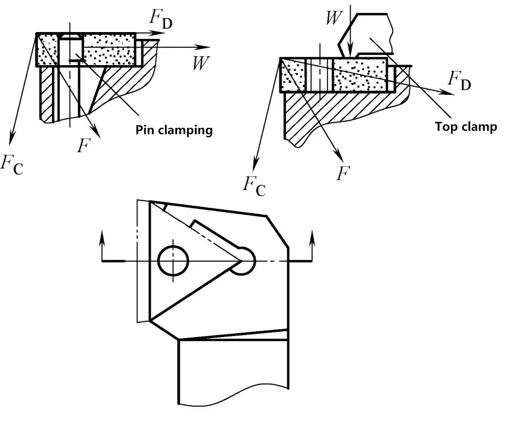
F₀, F₁—Cutting force components
F—Total cutting force
W—Clamping force
2) Positioning using the insert’s bottom surface, one side surface, and a hole mating with a movable center pin.
As shown in Figure 3. This positioning form makes the tool tip position accuracy related to the insert’s external dimensional accuracy, center hole accuracy, movable center pin dimensional accuracy, and fitting accuracy. The advantage is a relatively simple structure, and the insert pocket is easy to machine. This form is commonly used for eccentric pin clamped inserts.
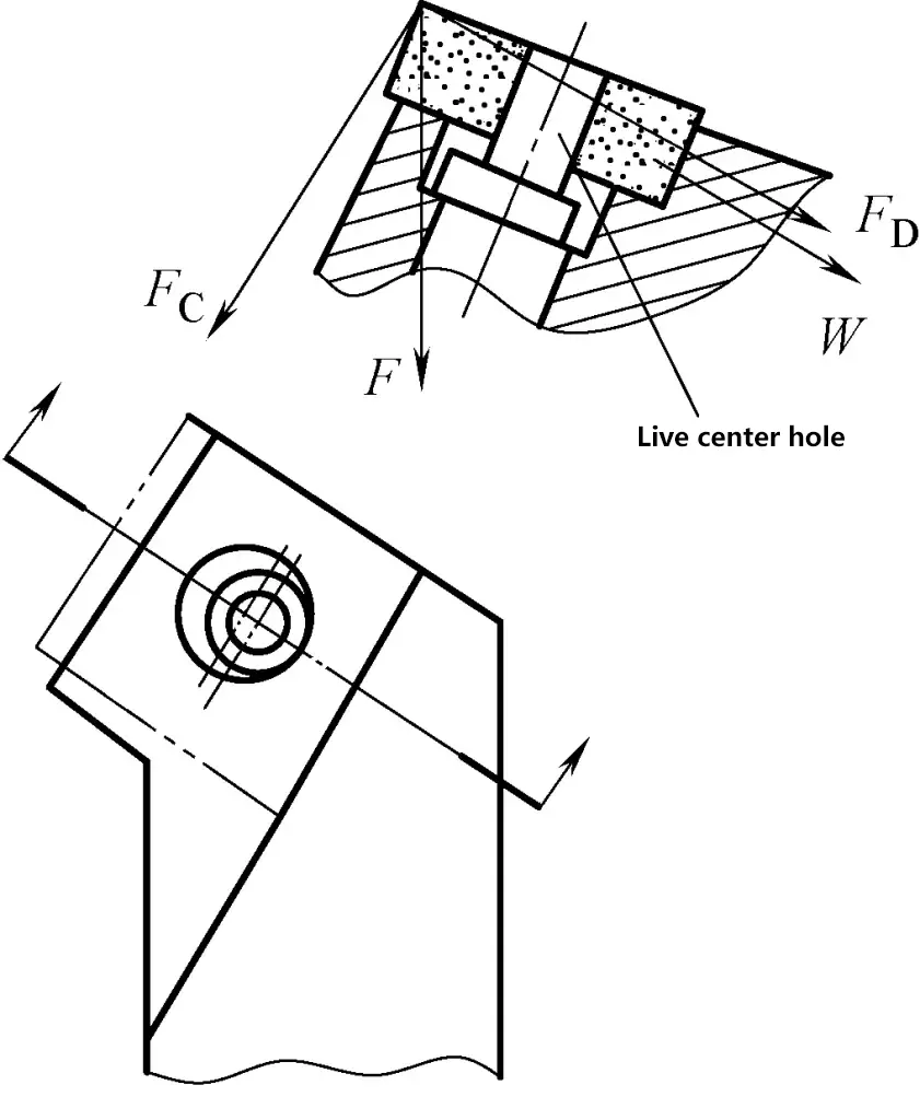
F₀, F₁—Cutting force components
F—Total cutting force
W—Clamping force
3) Positioning using the insert’s bottom surface, center hole, and one side surface in contact with the clamping element.
As shown in Figure 4, this positioning form makes the tool tip position accuracy related to the insert’s external dimensional accuracy, the dimensional and positional accuracy of the internal hole, and the dimensional accuracy of the fixed center pin. The positioning accuracy is better than the above forms, and the structure is relatively simple. The disadvantage is that the clamping force is in the opposite direction of the cutting force, requiring a large clamping force. This positioning form is commonly used for wedge pin clamped inserts.
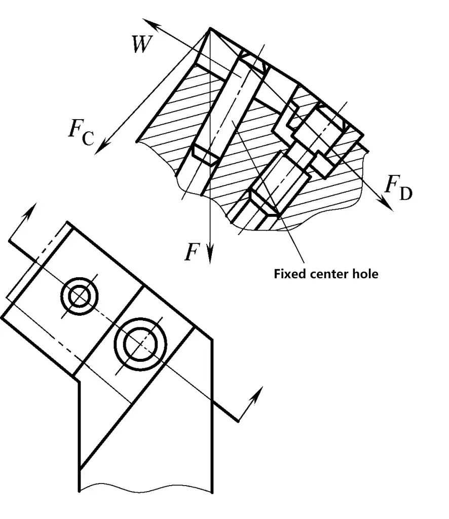
F₀, F₁—Cutting force components
F—Total cutting force
W—Clamping force
4) Positioning using the insert’s bottom surface, center hole, and one side surface.
As shown in Figure 5, the tool tip position accuracy of this positioning form is similar to the third form, but the force situation is better, requiring less clamping force. However, care should be taken that the side positioning point does not damage the unused cutting edges of the insert.
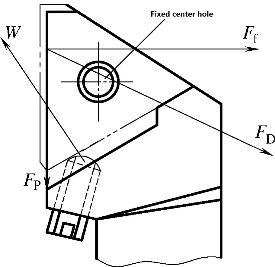
F₀, F₁, F₂—Cutting force components
W—Clamping force
Common clamping forms for indexable turning tools include:
1) Top clamp.
As shown in Figure 6, it uses the downward pressure of a clamp to press the insert firmly into the insert pocket. Its characteristics are large clamping force, stable and reliable positioning, simple structure, easy to use, and can clamp inserts without center holes. The disadvantage is that the tool head is bulky, affecting the operator’s line of sight. This clamping form is suitable for large and medium-sized lathes and intermittent cutting.
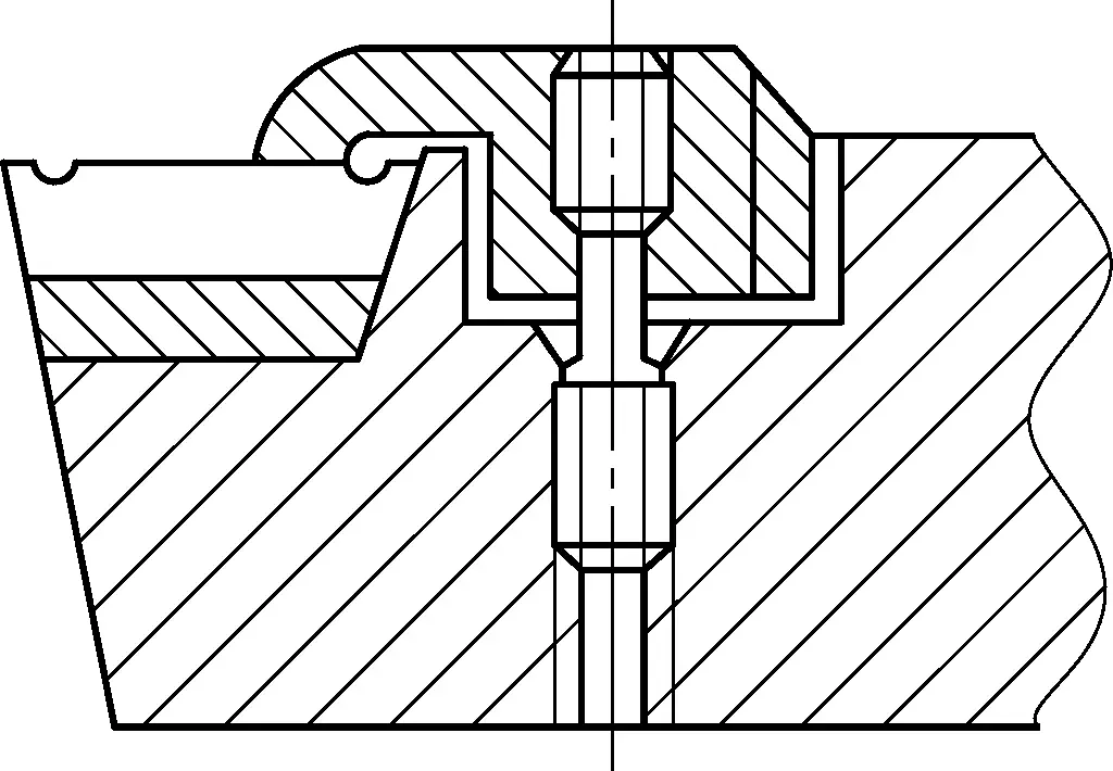
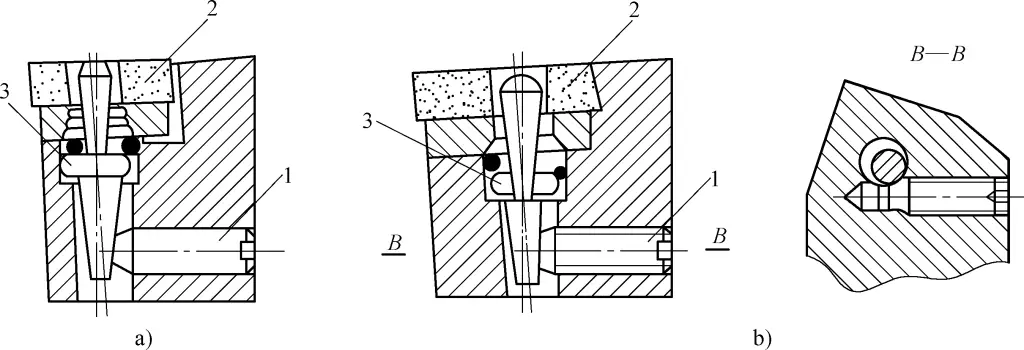
2) Eccentric pin clamp.
As shown in Figure 7, it uses the principle of eccentric clamping. When the eccentric pin (with or without threads) is tightened, its eccentricity clamps the insert in the insert pocket and self-locks. The advantage is a simple and compact structure, few components, easy to manufacture, and quick and easy insert indexing. The disadvantage is that clamping may not be very reliable under large impact loads, and tightening or loosening the eccentric pin is not very convenient. It is suitable for small turning tools.
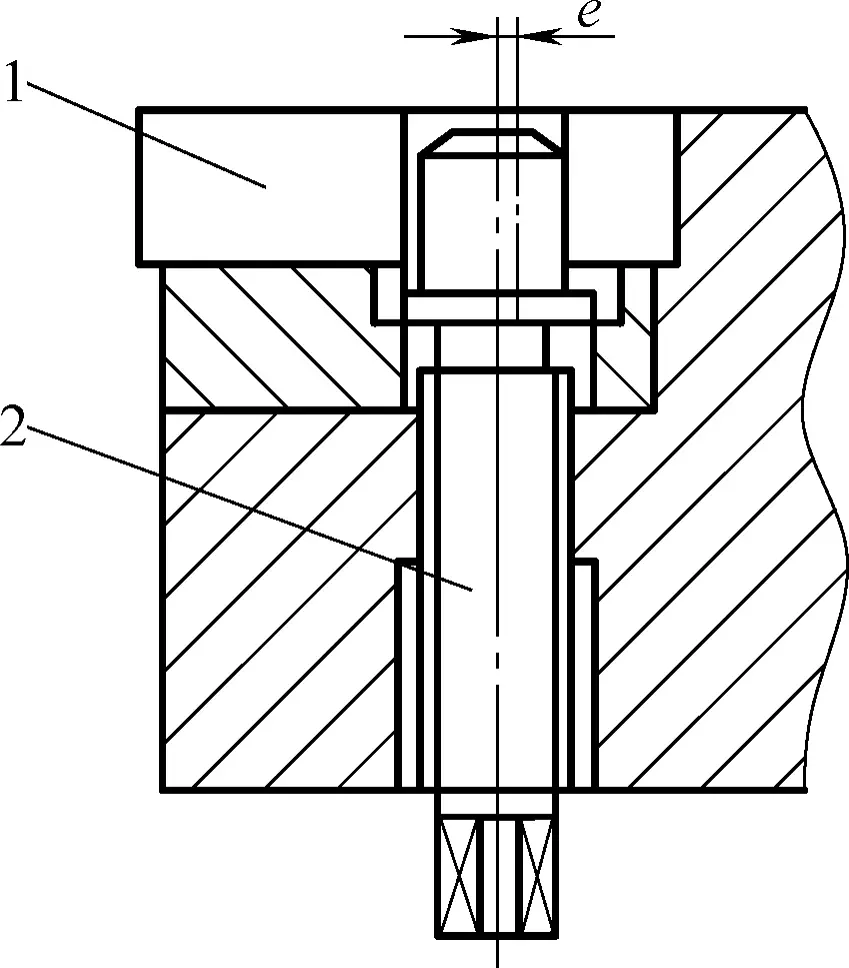
1—Insert
2—Eccentric pin
3) Lever pin clamp.
As shown in Figure 8, it uses the lever principle. When the screw applies force to the lower end of the lever pin, the lever pin uses the contact point with the tool holder hole wall as a fulcrum to press the insert firmly against the side of the insert pocket. Its advantages are stable clamping force direction, high positioning accuracy, and not too complex structure. The disadvantages are poor rigidity of the lever pin and small clamping travel. It is mainly suitable for
a) Direct force application
b) Tangential force application
1—Screw
2—Insert
3—Lever pin
4) Lever clamp.
As shown in Figure 1-30, this clamping method also uses the lever principle. Tightening the screw presses the lever to pivot, loosening or clamping the insert.
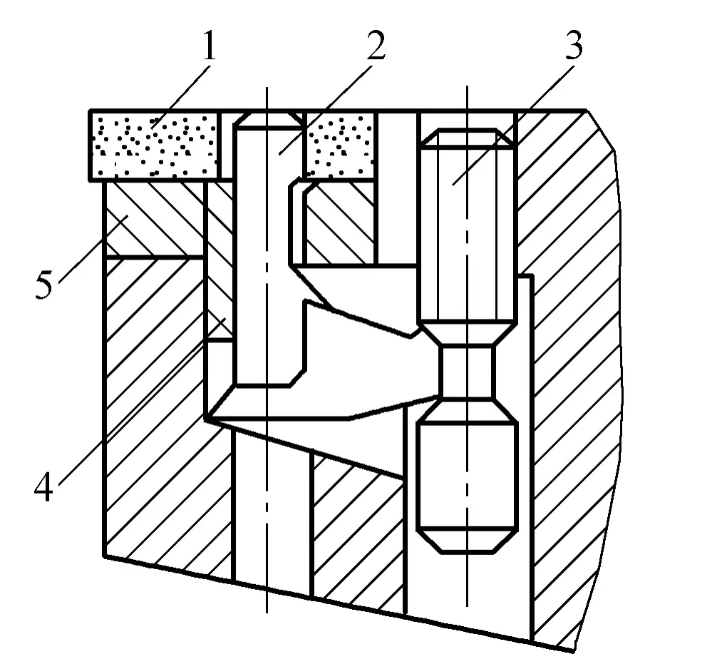
1—Insert
2—Lever
3—Screw
4—Spring sleeve
5—Shim
The advantages are stable and reliable clamping, relatively high positioning accuracy, and larger clamping travel, making insert indexing convenient. The disadvantage is a complex structure that is difficult to manufacture. It is suitable for cutting parameters: v₀ = 80~100m/min, f = 0.4~0.6mm/r, a₁ ≤ 8mm.
5) Wedge pin clamp.
As shown in Figure 10, this clamping method uses a screw to press the wedge block, which in turn presses the insert towards the fixed center pin under the action of the wedge. Its characteristics are simple structure, large clamping force, and easy to manufacture and use.
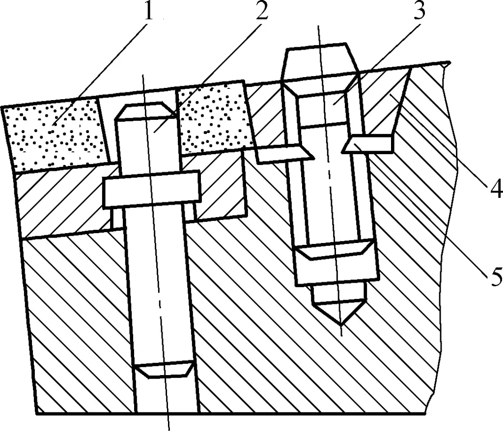
1—Insert
2—Screw
3—Pin
4—Wedge block
5—Washer
The disadvantage is that the central pin is easily deformed, resulting in low positioning accuracy, and the structure is not as compact as the lever type. Suitable cutting parameters are: vc ≤120m/min, f≤0.8mm/r, ap =4~6mm.
6) Composite type.
As shown in Figure 11, this clamping method adopts a composite structure that simultaneously clamps the blade using two clamping forms, such as wedge-pressure composite (Figure 11a) and pull-pressure composite (Figure 11b). It provides reliable clamping, can withstand large cutting loads and impacts, and is suitable for heavy-duty turning.

a) Wedge-pressure composite
b) Pull-pressure composite
1—Screw
2—Special wedge block
3—Blade
4—Tool pad
5—Locating pin
6—Tool shank
7—Pull-pressure plate
As shown in Figure 12, the tool features are as follows:
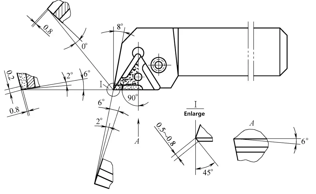
1) Blade material:
YT15 cemented carbide.
2) Tool features:
Based on the characteristics of slender shaft turning and drawing from the experience of welded turning tools for machining slender shafts, it is an improvement of some geometric angles of the standard 90° indexable external turning tool.
3) Cutting parameters:
vc =80~90m/min, f=0.3~0.4mm/r, ap =5~6mm.
4) Applicable range:
Rough turning of slender shafts with length-to-diameter ratios L/d=30~40 on C630 type lathe (extended).
5) Usage effects:
As shown in Figure 13. The tool features are as follows:
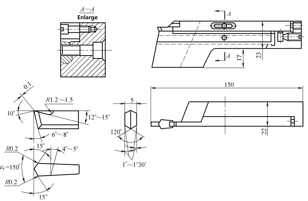
1) Blade material:
YT15 cemented carbide.
2) Tool features:
3) Cutting parameters:
vc =150~200m/min, f=0.15~0.2mm/r.
4) Applicable range:
For parting workpieces made of 20 steel or 45 steel with diameters less than 80mm on CA6140 or C630 type lathes, with coolant application.
5) Precautions:
As shown in Figure 14. The tool features are as follows:
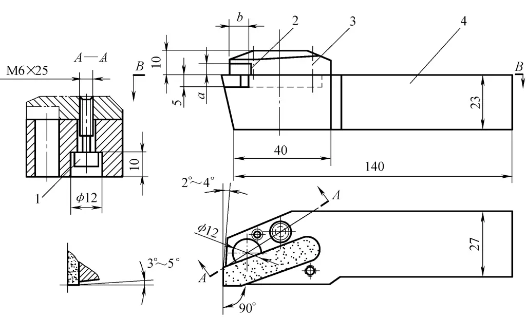
1—Screw
2—Chip collection port
3—Pressure plate
4—Tool body
1) Tool material:
Blade is YG8 cemented carbide; tool body is 45 steel, heat-treated and tempered, 230~250HBW.
2) Tool features:
3) Cutting parameters.
For rough turning (chip collection port size a×b=3.5mm×10mm): cutting speed vc =150m/min, feed rate f=0.15~0.3mm/r, depth of cut ap =4~5mm; For finish turning (chip collection port size a×b=1mm×4mm): vc =180m/min, f=0.06~0.18mm/r, ap =0.12~0.30mm.
4) Applicable range:
For turning brittle materials such as cast copper and cast iron on C6140 type lathe.
As shown in Figure 15. The tool features are as follows:
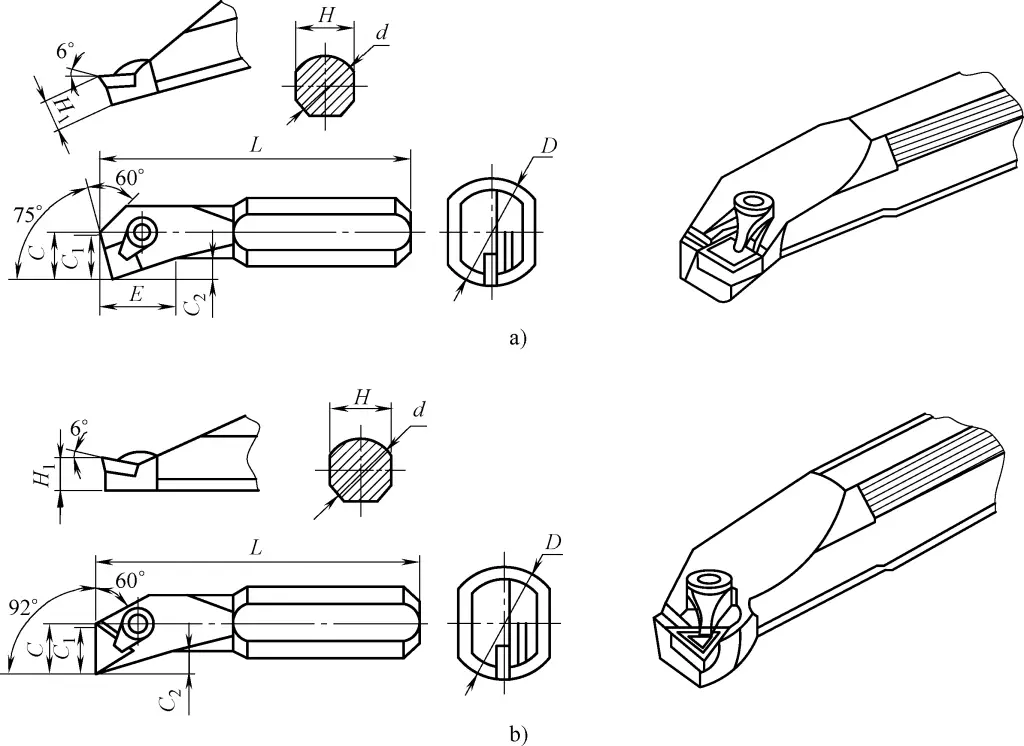
a) Through-hole boring tool
b) Blind-hole boring tool
1) Increased cross-sectional area of the tool shank.
As the tool tip is positioned on the center plane of the tool shank, the cross-sectional area of the shank in the hole can be maximized, resulting in good rigidity of the boring tool.
2) Adjustable overhang length of the tool shank.
The boring tool shank has two flat surfaces on the top and bottom, and the shank is made relatively long. During boring, the overhang length of the shank in the tool holder can be adjusted according to different hole depths. This not only increases the rigidity of the shank but also expands the application range of the boring tool.
The dimensions of each part of the boring tool are shown in Table 1.
Table 1 Dimensions of each part of the boring tool (unit: mm)
| Maximum boring diameter D | Tool shank dimensions | |||||||
| d | L | H | H1 | C | C1 | C2 | E | |
| 12 | 10 | 125 | 9.5 | 4.5 | 8.7 | 6.5 | 1.5 | — |
| 16 | 12 | 140 | 11.5 | 5.5 | 11.8 | 9 | 3 | — |
| 20 | 16 | 160 | 14 | 7 | 14 | 11 | 4 | 15 |
| 34 | 25 | 220 | 23 | 11.5 | 19.3 | 18 | 8 | 21 |
| 43 | 32 | 250 | 30 | 15 | 22.5 | 21.3 | 9 | 23 |
| 50 | 40 | 315 | 37 | 18.5 | 28 | 23.5 | 10.5 | 23 |
| 63 | 50 | 400 | 47 | 23.5 | 36 | 27.2 | 12.5 | 24 |
To improve tool performance, a layer or multiple layers of wear-resistant refractory compounds are coated on a tool substrate with good toughness through coating methods. This combines the tool substrate with a hard coating to increase the surface hardness of the tool and improve its wear resistance and lubricity.
Based on the different substrate materials, coated tools can be classified into high-speed steel coated tools, cemented carbide coated tools, ceramic coated tools, diamond coated tools, and cubic boron nitride coated tools.
Cemented carbide coated tools are created by depositing a layer of TiC, TiN, or A3120 compound material with a thickness of 5~12μm or less on the surface of cemented carbide inserts through chemical vapor deposition and vacuum sputtering methods. According to different coating methods, coated tools can be divided into chemical vapor deposition (CVD) coated tools and physical vapor deposition (PVD) coated tools.
For cemented carbide tool substrates, coating is generally done using the chemical vapor deposition (CVD) method, with a deposition temperature of about 1000°C. For high-speed steel tool substrates, coating is generally done using the physical vapor deposition (PVD) method, with a deposition temperature of about 500°C.
Coated tools have high oxidation resistance and adhesion properties, maintaining the good toughness and high strength of the substrate while also having the high hardness, high wear resistance, and low friction coefficient of the coating, which reduces cutting forces and cutting temperatures. After coating a 5~6μm thick TiC layer on a cemented carbide tool substrate, its surface hardness can reach 2500~4200HV.
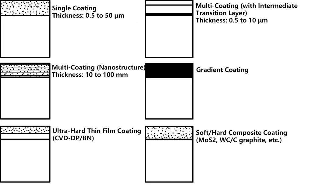
Coating methods include single-layer coating, multi-layer coating, gradient coating, super-hard thin film coating, soft/hard composite coating, etc., as shown in Figure 16.
Common coating materials are TiC, TiN, TiCN, Al2 O3 , etc. Coating materials have evolved from the initial TiC and TiN coatings to composite multi-layer coatings, such as TiC, TiN, TiCN, TiC/TiCN/TiN, TiC/A1203, TiC/A1203/TiN, TRAIN, etc., and their combinations.
Their common characteristics are high hardness, good chemical stability, resistance to diffusion wear, low friction coefficient, resulting in lower cutting forces, reduced cutting temperatures, and significantly improved cutting performance of the tools.
TiC coating is currently the most widely used coating material, with good resistance to wear and crater wear. It easily diffuses into the substrate, adheres firmly to the substrate, and has high wear resistance at low cutting temperatures. It is typically used in situations where severe wear occurs.
TiN coating has slightly lower hardness than TiC, with low affinity for metals and good wettability. Currently, the usage rate of TiN-coated high-speed steel tools in industrially developed countries has reached 70% of high-speed steel tools. It has a high resistance to crater wear but adheres less firmly to the substrate.
Al2 O3 coating has good chemical stability, thermal stability, and high oxidation resistance. Al2 O3 coating maintains good chemical and thermal stability at high temperatures, making it suitable for high-speed cutting.
TiCN coating combines the properties of TiC and TiN, with higher hardness than both TiC and TiN. To significantly improve tool life, TiCN can be used as the main wear-resistant layer for tools. TiCN is a relatively ideal tool coating material.
TiAIN coating has good chemical stability, high hardness, and strong resistance to oxidation, adhesion, and diffusion wear. It shows notable effects in high-speed cutting and is particularly suitable for machining wear-resistant materials such as gray cast iron and silicon-aluminum alloys.
Currently, the proportion of coated cemented carbide indexable inserts in foreign countries exceeds 70%, and they are widely used in machining various steel parts, cast iron, stainless steel, and high-temperature alloys. Presently, coating technology has been applied to end mills, shaving cutters, broaching tools, forming pulling tools, reamers, gear hobs, and various mechanically clamped indexable inserts to meet the needs of high-speed cutting and machining.
Diamond is an allotrope of carbon and is the hardest known natural material.
Diamond tools have high hardness, high wear resistance, and high thermal conductivity. They can precisely cut non-ferrous metals, alloys, and high-hardness wear-resistant materials, especially in high-speed cutting of aluminum and silicon-aluminum alloys (Table 2). Diamond tools are the primary cutting tools that are difficult to replace.
Table 2 Materials suitable for machining with diamond tools
| Workpiece material | Machining objects | |
| Non-ferrous metals | Aluminum and aluminum alloys | Aircraft, automobiles, motorcycles: pistons, cylinders, compressor parts, transmissions, various housing components, etc. Precision machinery: cameras, photocopiers, measuring instruments, gas appliances, etc. General machinery: various pump bodies, hydraulic presses, mechanical parts, etc. |
| Copper and copper alloys | Internal combustion engines, ships: various shafts, bearings, pump bodies, gears, rotor blades Electronic instruments: various meters, electric motors, commutators, etc. General machinery: various shafts, bearings, valve bodies, casings, etc. | |
| Cemented carbide | Various valve seats, cylinders and other sintered products and semi-finished sintered products | |
| Others | Various non-ferrous metals such as titanium, magnesium, zinc, lead, etc. | |
| Non-metallic | Wood | Various chipboard and artificial wear-resistant fiberboard products |
| Reinforced plastics | Glass fiber, carbon fiber reinforced plastics | |
| Rubber | Rubber bonded grinding wheels, rubber rings, paper calender rolls, etc. | |
| Graphite | Carbon rods, etc. | |
| Ceramics | Sealing rings, plungers and other sintered and semi-sintered products | |
Natural diamond is the hardest substance discovered in nature. Its microhardness is as high as 10000HV. The wear resistance of natural diamond is 80-120 times that of cemented carbide, while synthetic diamond’s wear resistance is 60-80 times that of cemented carbide.
The friction coefficient between diamond and some non-ferrous metals is very low, usually between 0.1 and 0.3. Low friction coefficient leads to small deformation and reduced cutting force during processing.
The cutting edge of diamond tools can be ground very sharp, with a typical tool tip radius of 0.1-0.5μm. Natural single crystal diamond tools can reach as high as 0.002-0.008μm. Therefore, it can perform ultra-thin cutting and ultra-precision machining.
The thermal expansion coefficient of diamond is about 1/10 that of high-speed steel, so diamond tools do not produce large thermal deformation, which is particularly important in precision and ultra-precision machining.
The thermal conductivity of diamond can reach 9 times that of cemented carbide. Due to its high thermal conductivity and thermal diffusivity, cutting heat is easily dissipated, resulting in low temperature at the cutting part of the tool.
Currently, there are two types of diamond cutting tools: single crystal diamond tools and polycrystalline diamond tools. Polycrystalline diamond tools include polycrystalline diamond (PCD) tools and chemical vapor deposition (CVD) diamond tools.
Single crystal diamonds can be divided into natural single crystal diamonds and artificially synthesized single crystal diamonds. Most natural diamonds are regular octahedrons or rhombic dodecahedrons, with a few being cubic or other shapes. They are light-colored, transparent, free of impurities and defects, and have a strong refractive index.
Natural single crystal diamond tools are made by fixing a single large diamond particle, which has been ground into a certain geometric shape and size, onto a tool shank or tool body using welding, bonding, mechanical clamping, or powder metallurgy methods, and then mounting it on a precision machine tool.
After fine grinding, the cutting edge of natural single crystal diamond tools can be extremely sharp, with an edge radius as small as 0.002μm, enabling ultra-thin cutting. Combined with its low friction coefficient with the workpiece material, good anti-adhesion properties, lack of affinity for non-ferrous metals, low thermal expansion coefficient, and high thermal conductivity, natural diamond tools can produce extremely high workpiece accuracy and extremely low surface roughness values.
Therefore, cutting with natural diamond tools is also called mirror cutting, and natural diamond tools are universally recognized as ideal and irreplaceable ultra-precision machining tools.
Since single crystal diamonds have anisotropic properties, it is necessary to choose the correct crystal orientation when designing and manufacturing single crystal diamond tools, and the diamond raw material must undergo crystal orientation. Due to the complex manufacturing technology and high production costs of artificial single crystal diamonds, the vast majority of single crystal diamond tools are currently made from natural single crystal diamonds.
Using single crystal diamond tools on ultra-precision lathes can achieve mirror-like finishes. Single crystal diamond tools are currently the main tools in the field of ultra-precision cutting, with their edges capable of being ground extremely sharp, producing workpieces with very low surface roughness values and having very high tool life. Currently, single crystal diamond tools are widely used in machining computer disk substrates, laser reflectors, and various optical instruments.
Since the successful development of polycrystalline diamond (PCD) inserts by GE in the early 1970s, PCD has been more widely applied than natural diamond tools due to its abundant raw material sources and much lower cost, with prices only a fraction (from one-tenth to one-sixtieth) of natural diamond.
PCD tools cannot be ground to have extremely sharp edges, and their edge radius is much larger than that of natural diamond tools. The surface quality of workpieces machined with PCD tools is also not as good as those machined with natural diamond tools, making it difficult to achieve ultra-precision mirror cutting.
Although PCD has lower hardness than single crystal diamond, PCD is an isotropic material, so preferential orientation is not required in tool manufacturing. The conductive nature of PCD binders makes it easy to cut and shape PCD.
PCD tools are mainly used for machining wear-resistant non-ferrous metals and their alloys, as well as non-metallic materials. They can maintain sharp edges and cutting efficiency over long cutting processes and are widely used in high-speed precision machining of some difficult-to-machine non-ferrous metal and alloy parts, as well as non-metallic materials (such as graphite, carbon, glass, hard rubber wood, ceramics, plastics, corundum, bakelite, and glass fiber reinforced composite materials).
Structurally, PCD tools can be divided into brazed PCD tools and indexable inserts, integral polycrystalline diamond inserts, and polycrystalline diamond composite inserts. Currently, most PCD inserts used are composite inserts sintered with cemented carbide substrates.
Indexable PCD inserts are made by mounting a PCD blank on a cemented carbide indexable insert and then grinding the edge. They can be clamped in various tool holders, tool clamps, or tool discs of CNC machines for highly reliable mass production.
Polycrystalline diamond turning tools use polycrystalline diamond composite inserts. The upper layer of the insert is fine-grained synthetic diamond, and the lower layer is a cemented carbide substrate, sintered under high pressure and high temperature to form a circular polycrystalline diamond composite insert blank.
Since the emergence of CVD diamond technology in Japan in the 1970s and 1980s, this technology has been rapidly applied to cutting tools.
CVD diamond refers to diamond films synthesized on heterogeneous substrates (such as cemented carbide, ceramics, etc.) using chemical vapor deposition (CVD) method. CVD diamond contains no metal or non-metal additives, and its performance is very close to natural diamond, combining the advantages of single crystal diamond and polycrystalline diamond (PCD), and to some extent overcoming their shortcomings.
Different CVD deposition processes can be selected to synthesize PCD with different grain sizes and surface morphologies according to different application requirements.
Extensive practice has shown that the performance of CVD diamond tool products surpasses similar PCD products in many aspects, and their surface roughness is close to that of single crystal diamond, while their impact resistance exceeds that of single crystal diamond. CVD diamond is considered a promising new diamond material.
The super-hard wear resistance and good toughness of CVD diamond tools allow them to machine most non-metallic materials and various non-ferrous metal materials, such as aluminum, silicon-aluminum alloys, copper, copper alloys, graphite, ceramics, and various glass fiber and carbon fiber reinforced structural materials. CVD diamond tools can also be used as high-efficiency and high-precision machining tools, with costs far lower than expensive natural diamond tools.
CVD diamond tools can be made in two forms: one is a thin film with a thickness of less than 50μm deposited on the substrate, known as CVD diamond thin film coated tools; the other is a thick film without a substrate, with a thickness of up to 1mm, known as CVD diamond thick film brazed tools, which can be brazed onto a substrate if needed.
CVD diamond thin film coated tools have an integral diamond surface coating and can be machined into cutting edges of any style and geometric shape. Diamond thin film coated tools are superior to PCD tools in some aspects.
Since CVD diamond thin films can be deposited on substrates of any shape, CVD diamond thin film coated tools are easy to manufacture into complex profile tools. Moreover, CVD diamond thin film coated tools have a simple manufacturing process, low cost, and a wide variety of potential tool types, making them a future development direction with great potential.
CVD thick film diamond is pure diamond, with hardness close to natural diamond and much higher than PCD. Unlike natural diamond, CVD thick film diamond is isotropic and has a lower cost, so it will replace PCD in many aspects. If the deposition quality is further improved, it may also replace natural diamond in ultra-precision machining.
Due to the high wear resistance and high thermal stability of CVD thick film diamond, it has great potential in the field of high-speed cutting of highly wear-resistant materials. The three types of diamond tools mentioned above each have their own characteristics, as shown in Table 3.
Table 3 Comparison of characteristics of single crystal diamond, PCD diamond, and CVD diamond tools
| Characteristics | Single crystal diamond tools | Polycrystalline diamond tools (PCD) | CVD diamond tools |
| Material structure | Pure diamond | Contains Co binder | Pure diamond |
| Wear resistance | Higher than PCD and diamond film | Varies with diamond particle size | 2-10 times higher than PCD |
| Toughness | Poor | Excellent | Good |
| Chemical stability | High | Relatively low | High |
| Machinability | Poor | Excellent | Poor |
| Solderability | Poor | Excellent | Poor |
| Cutting edge quality | Excellent | Good | Excellent |
| Applicability | Ultra-precision machining | Rough machining, precision machining, not suitable for machining organic composite materials | Precision machining, semi-precision machining, continuous cutting, wet cutting, dry cutting, suitable for machining organic composite materials |
Taking PCD tools as an example, their geometric parameters should be determined according to different processing materials. The reasonable selection of geometric angles for the cutting part has a significant impact on tool life, as shown in Table 4.
Table 4 Selection of geometric angles for PCD tools
| Angle | Selection |
| Rake angle γo | For rough turning of high hardness materials, generally use a larger negative rake angle of -10° to -5°; for lower hardness, a smaller negative rake angle can be used; For fine turning, generally use 0°, or even a positive rake angle of 0° to 10° |
| Clearance angle αo | When the workpiece material has higher hardness, 8° to 12° can be used; when the workpiece material has lower hardness, 10° to 20° can be used |
| Inclination angle λs | For rough turning, generally use a smaller inclination angle to increase cutting edge strength; for fine turning, generally use a larger inclination angle to reduce radial cutting force |
| Lead angle kr | Generally use 75° to 90°. When rough turning high hardness materials, the lead angle can be 90° to maintain tool strength and impact resistance. When machining slender workpieces, a larger lead angle can be chosen to reduce radial cutting force; for fine turning, a smaller lead angle can be used to improve surface quality |
Cubic Boron Nitride (CBN) is an allotrope of Boron Nitride (BN), with a structure similar to diamond. It has ultra-hard properties, high thermal stability, and high chemical stability. It does not oxidize even when heated to 1000°C in the atmosphere and is widely used in the processing of iron and steel products.
Due to their superior performance, Cubic Boron Nitride tools can be used for cutting high-speed steel, tool steel, hardened steel, chill-hardened cast iron, bearing steel, high-temperature alloys, and other difficult-to-machine materials.
Cubic Boron Nitride (CBN) comes in single crystal and polycrystalline forms, namely single crystal CBN and Polycrystalline Cubic Boron Nitride (PCBN).
CBN has hardness and strength close to diamond. The microhardness of CBN powder is 8000-9000HV, and the hardness of PCBN sintered body reaches 3000-5000HV. When cutting wear-resistant materials, its wear resistance is 30 times that of coated carbide tools.
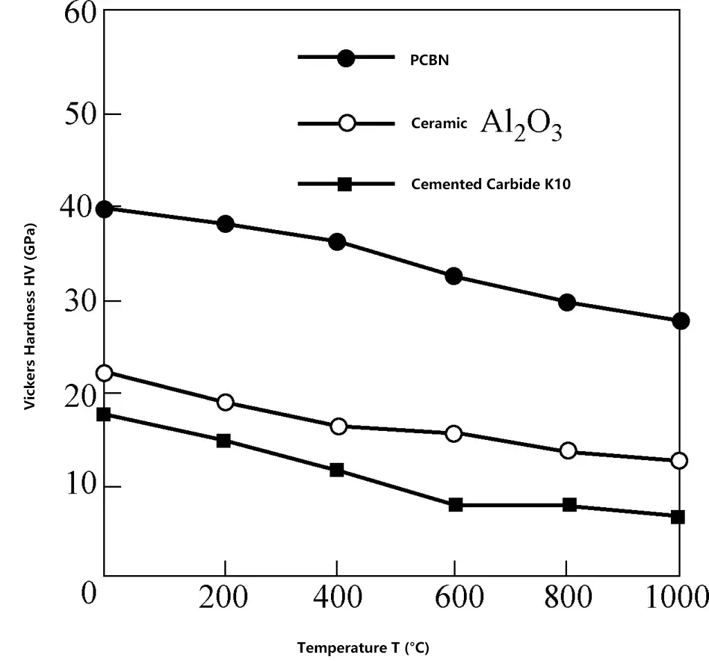
CBN has higher heat resistance than diamond, reaching 1400-1500°C. The hardness of PCBN at 1000°C is still higher than the room temperature hardness of ceramics and carbides. Figure 17 shows a comparison of high-temperature hardness between PCBN, ceramics, and carbides.
CBN has very high oxidation resistance and does not oxidize even at 1000°C. It also does not react chemically with ferrous materials up to 1200-1300°C, showing high chemical inertness.
CBN’s thermal conductivity is second only to diamond, 20 times that of carbide. The ratio of CBN to ceramic thermal conductivity is 37.1. High thermal conductivity in high-speed cutting can lower the temperature at the tool tip, reducing tool wear and improving machining accuracy.
The friction coefficient between CBN and different materials is 0.1-0.3. In high-speed cutting, a small friction coefficient can reduce cutting force, lower cutting temperature, and improve machining surface quality.
Cubic Boron Nitride (CBN) comes in single crystal and polycrystalline forms, namely single crystal CBN and Polycrystalline Cubic Boron Nitride (PCBN). Single crystal CBN is usually obtained by sintering hexagonal boron nitride (HBN) under high temperature and high pressure with the participation of catalysts and additives.
PCBN is a polycrystalline material formed by sintering fine CBN materials together with binding phases (TiC, TiN, Al, Ti, etc.) under high temperature and high pressure. It is collectively referred to as super-hard tool materials along with diamond.
Due to limitations in manufacturing technology and high costs of single crystal CBN, PCBN is still the main form used in practical applications. PCBN tools have unique structure and characteristics and have been widely used in recent years for cutting ferrous metals, especially suitable for cutting difficult-to-machine materials such as hardened steel, high-hardness cast iron, and high-hardness thermal spray alloys.
PCBN tools are divided into two main categories according to their structure: PCBN brazed tools and PCBN indexable tools.
PCBN brazed tools are made by brazing PCBN inserts onto a steel substrate and then grinding. PCBN indexable inserts are generally made by brazing a PCBN insert onto one corner of an indexable carbide insert and then grinding.
According to different composite manufacturing methods, PCBN tools can be divided into solid PCBN inserts and PCBN composite inserts sintered with carbide. Solid PCBN inserts have multiple cutting edges and can be indexed. PCBN composite inserts have multiple cutting edges, can be indexed, and can also be reground.
PCBN composite inserts are made by sintering a 0.5-1.0mm thick layer of PCBN on carbide with good strength and toughness, combining good toughness with high hardness and wear resistance. This solves problems such as low bending strength and difficult brazing of CBN inserts.
Taking the machining of hardened steel as an example, the selection range of PCBN tool geometric angles is shown in Table 5.
Table 5 Selection of geometric angles for PCBN tools
| Angle | Selection |
| Rake angle γo | When machining hardened steel, the tool tip angle should not be too small. The tool rake angle is generally -10° to 0°, usually 0° |
| Clearance angle αo | The clearance angle is generally small, between 6° and 10°, to ensure that the wedge angle of the cutting part of the tool is large enough |
| Inclination angle λs | When there are no special requirements, the inclination angle is often 0° or negative, to ensure a better stress state when the cutting edge enters |
| Nose angle εr | The nose angle should generally not be less than 90°, and the tool tip should be ground into a circular arc of ϕ (0.4-1.2) mm to ensure sufficient strength of the tool tip |
Ceramic tools are made from synthetic compounds, formed under high pressure and sintered at high temperatures. They have very high hardness and wear resistance, heat resistance up to 1200°C and above, good chemical stability, and are not easily bonded with metals.
Now, due to improved manufacturing methods, microstructure refinement, high densification, and the addition of carbides, nitrides, borides, oxides, and other metals (such as Ni, Mo) to their composition, ceramic tools have significantly improved bending strength, fracture toughness, and impact resistance. Ceramic tools are widely used in high-speed cutting, dry cutting, hard cutting, and cutting of difficult-to-machine materials.
The room temperature hardness reaches 93-95HRA, and the cutting speed is 5-10 times higher than that of carbide, thus having a very high tool life. It is suitable for machining high-hardness materials that are difficult to machine with traditional tools and is suitable for high-speed cutting situations.
The hardness at 1200°C is 80HRA, and it can still perform cutting. Ceramic tools have excellent high-temperature mechanical properties, with a hardness of 87HRA at 800°C, and the bending strength at high temperatures decreases very little. Therefore, ceramic tools can have very high cutting speeds.
Ceramics have very little affinity with metals, have good anti-adhesion ability, and have less adhesive wear on the tool, which can reduce the tool’s adhesive wear.
Ceramic tools have characteristics such as corrosion resistance, diffusion resistance, oxidation resistance, and good chemical stability.
The lower friction coefficient reduces cutting forces and cutting temperatures, and chips are less likely to adhere, making it less likely to produce built-up edges, thus resulting in good machined surface quality.
The earliest to appear was pure alumina ceramic, with the main component being alumina (Al2 O3 ) and a small amount of magnesium oxide used for grain refinement, made by cold pressing and sintering, with a hardness of 92-94HRA, relatively low bending strength and toughness, and a limited range of use.
Subsequently, composite alumina ceramics were developed on this basis, which involve adding alloying elements such as TiC, Ni, and Mo to the Al2 O3 matrix, formed by hot pressing, with a hardness reaching 93-94HRA. Their strength, hardness, and toughness have significantly improved, with noticeable increases in cutting speed and feed rate, rapidly expanding their range of use.
Due to the continuous maturation of research and development technology, ceramic tools with TiB2 , Ti(C, N), SiCw, ZrO2 , etc., added to Al2 O3 have appeared, further improving various properties and being widely used in fine machining or semi-fine machining of carbon steel, alloy steel, and cast iron. Table 6 lists the properties of typical alumina-based ceramic tool materials in China.
Table 6 Properties of typical alumina-based ceramic tool materials in China
| Grade | Main components | Density/(g/cm) | Hardness/HRA | Bending strength/MPa | Fracture toughness/MPa·m1/2 |
| LT-55 | Al2O3/TiC | 4.96 | 93.7~94.8 | 900 | 5.04 |
| SG-4 | Al2 O3 /(Ti, W)C | 6.65 | 94.7~95.3 | 850 | 4.94 |
| LX-1 | Al2O3/SiCw | 3.63 | 94~95 | 700~800 | 8.5 |
| LP-1 | Al2O3/TiR2 | 4.08 | 94~95 | 800~900 | 5.2 |
| LP-2 | Al2O3/TiB2/SiCw | 3.94 | 94~95 | 700~800 | 7.8 |
The earliest to appear was Si3 N4 ceramic cutting tools, which have low thermal expansion coefficient, good chemical stability, and good thermal shock resistance. Its thermal stability and thermal crack resistance are higher than Al2 O3 , suitable for high-speed machining of cast iron and cast iron alloys, cold hard cast iron, and other high-hardness materials.
Subsequently, Si3 N4 /TiC ceramic cutting tools were developed. These tools have excellent wear resistance, heat resistance, and thermal shock resistance. By adding TiC to the Si₃N₄ matrix, cutting performance was further improved, with tool life being ten times that of carbide tools.
With the continuous maturation of research and development technology, Sialon ceramic cutting tools appeared internationally. Sialon ceramic cutting tools are materials obtained by hot-press sintering a mixture of aluminum nitride, alumina, and silicon nitride at high temperatures.
Y2 O3 was added to the structure to make it denser. Sialon ceramic cutting tools have good comprehensive performance, with high strength and toughness, mainly used for machining difficult-to-cut materials such as cast iron and nickel-based alloys.
Currently, many new ceramic cutting tool materials have been developed, such as nanocomposite ceramic cutting tools, whisker-reinforced ceramic cutting tools, functionally graded ceramic cutting tools, powder-coated ceramic cutting tools, self-lubricating ceramic cutting tools, etc.
The selection of commonly used geometric angles for ceramic cutting tools is shown in Table 7.
Table 7 Selection of geometric angles for ceramic cutting tools
| Angle | Selection |
| Rake angle γo | Ceramic cutting tools generally use negative rake angles for cutting, usually ranging from -10° to -50° depending on the hardness of the workpiece material |
| Clearance angle αo | The recommended clearance angle for ceramic cutting tools is generally 5° to 12°. When turning high-hardness cast iron and quenched steel, a larger clearance angle of 8° to 10° is generally chosen |
| Major cutting edge angle kr | The size of the major cutting edge angle is mainly chosen based on the rigidity of the technological system, generally 30° to 75°. When turning slender workpieces, to reduce the back force and deformation, a larger major cutting edge angle should be chosen, generally 45° to 75°. When machining various sprayed and welded materials, to reduce tool wear and increase the contact width between the cutting edge and the machined surface, a smaller major cutting edge angle should be chosen, generally 25° to 30° |
| Inclination angle λs | When ceramic cutting tools are used for machining steel and cast iron, especially when cutting high-hardness materials and intermittent cutting, negative inclination angles are used. Generally recommended to be -10° to 0° |
By analyzing the geometric parameters of standard twist drills, the following main defects can be found:
The above-mentioned defects caused by the geometric structure of standard twist drills seriously affect their cutting performance. To improve the geometric structure of the cutting part of the drill and increase work efficiency, the following grinding is often performed on the cutting part when using standard twist drills.
1) Grinding the face.
(Figure 18) This mainly changes the size of the rake angle and the form of the face to meet the needs of machining different materials. There are two methods for grinding the face: one is to grind the face near the outer edge of the drill flat to reduce the rake angle and increase the strength of the cutting edge, as shown in Figure 18a. This is used for drilling materials with high strength and hardness, and when using twist drills for hole enlargement, to prevent the drill from digging in.
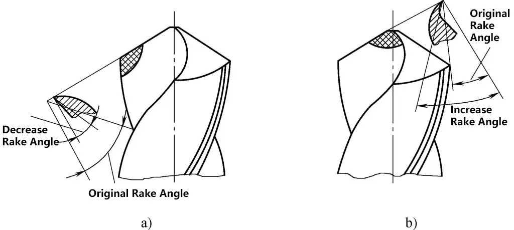
a) Reducing the rake angle at the outer edge
b) Increasing the rake angle at the drill core
The other method is to grind the rake angle at the drill core (Figure 18b) to increase the rake angle, reduce cutting force, and make cutting smoother. This is used for drilling materials with lower strength.
2) Grinding the chisel edge.
(Figure 19) There are two methods for grinding the chisel edge: shortening the chisel edge and improving the rake angle of the chisel edge. These two methods are usually combined. During drilling, this can reduce feed force, improve the drill’s centering ability, and improve cutting conditions.
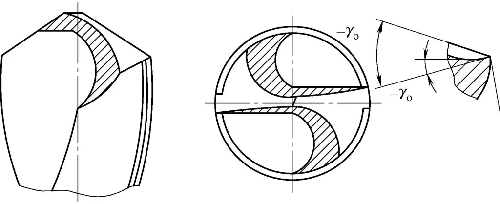
The grinding standard is: the softer the workpiece material, the shorter the chisel edge should be ground; the harder the workpiece material, the less the chisel edge should be ground.
3) Grinding the margin.
Since the secondary clearance angle α’ of standard twist drills is 0°, to reduce friction between the drill margin and the hole wall and reduce drill wear, the back of the margin can be ground, as shown in Figure 20.
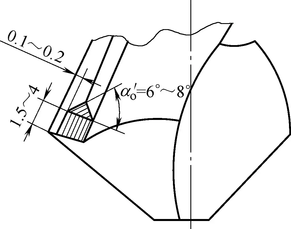
Grind out a secondary clearance angle α’ o = 6° to 8°, reducing the margin width to 0.1-0.2mm, with a grinding length of about 1.5-4mm. This is used for drills with larger diameters, machining ductile materials or soft metals, can improve the machined surface quality, and can be used for semi-finishing holes.
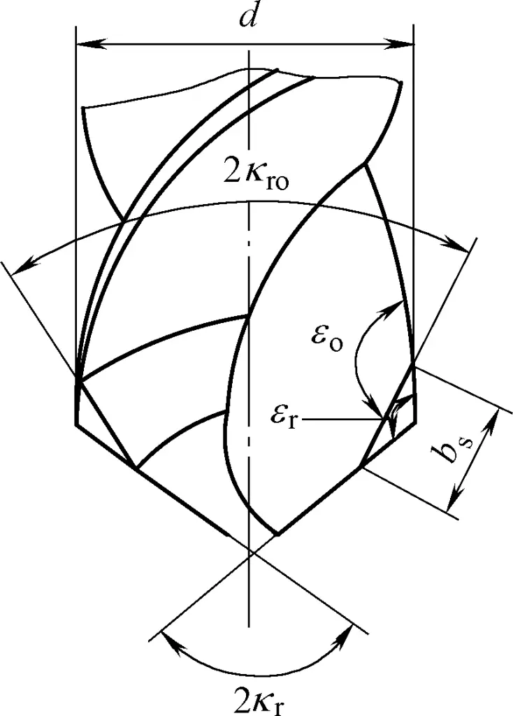
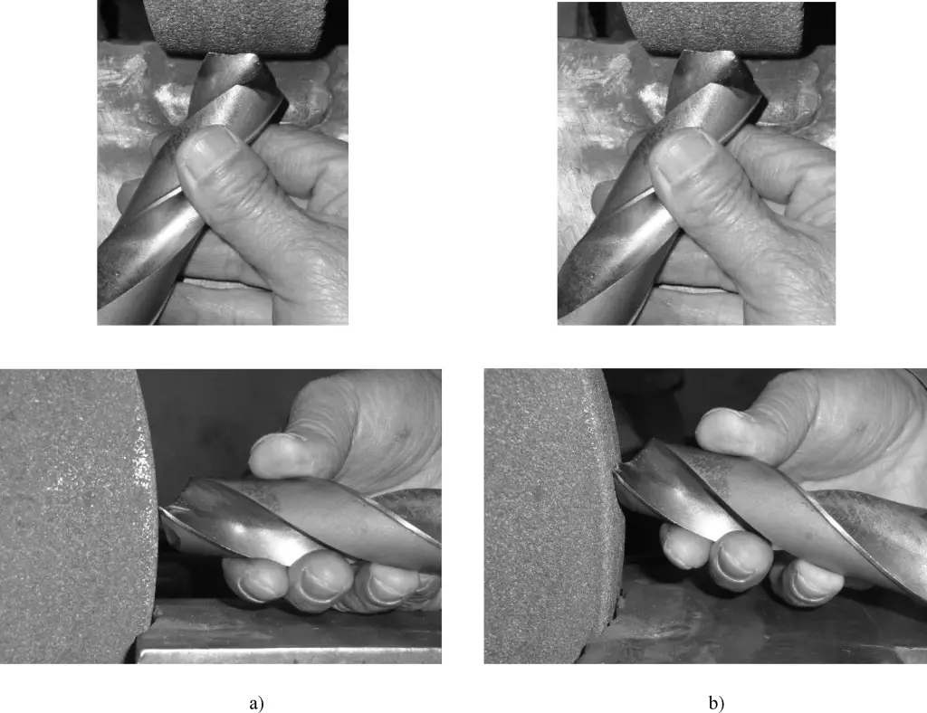
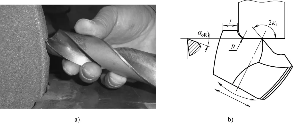
4) Grinding the point angle.
Grind the two cutting edge points of the drill into a straight line or arc transition edge, forming a double point angle, as shown in Figure 21. Generally, 2Kro = 70° to 75°, bs = 0.2d. After grinding, the point angle at the outer edge increases, the load-bearing capacity of the cutting edge improves, feed force decreases, heat dissipation conditions improve, and drill life increases. This is particularly effective when drilling cast iron and cast steel parts with hard skin.
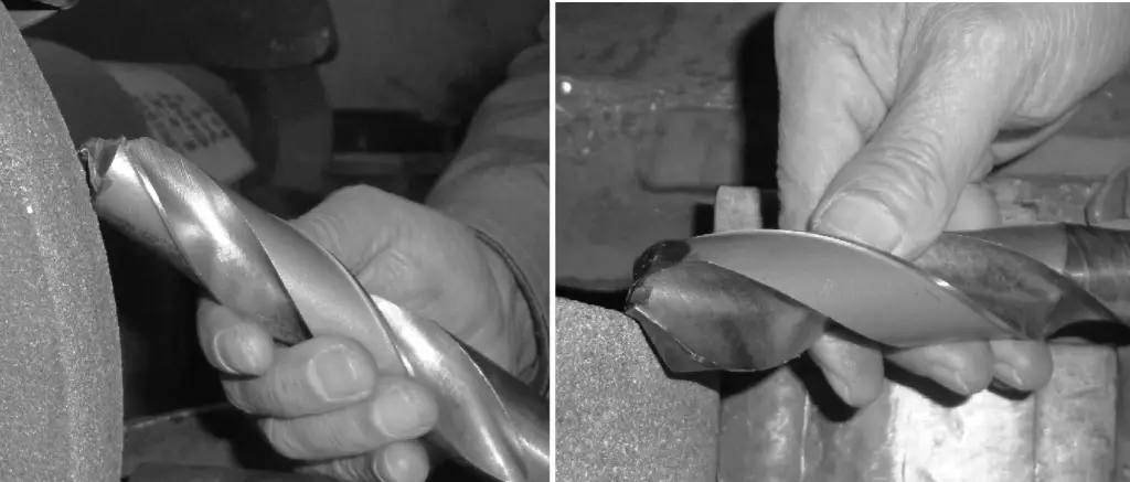
5) Creating chip-breaking grooves.
(Figure 22) When the twist drill is relatively large, chip-breaking grooves can be ground alternately on the two main back faces of the drill (Figure 22a), or chip-breaking grooves can be manufactured on the face during drill production (Figure 22b).
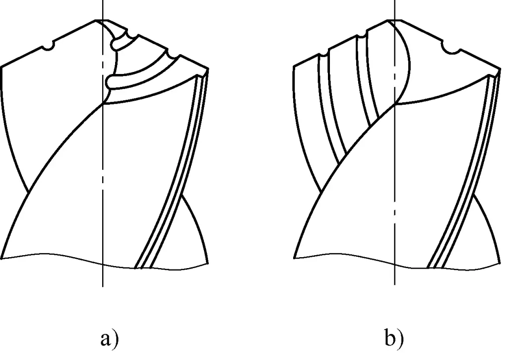
a) Creating chip-breaking grooves on the main back face
b) Manufacturing chip-breaking grooves on the face
During drilling, this can divide the chips into narrow strips, reducing cutting deformation, facilitating chip removal, reducing cutting force, promoting cooling and lubrication in the cutting zone, and improving cutting conditions. It is suitable for drilling large and deep holes in ductile materials.
Gang drills are a type of drill that has been revolutionized through long-term practice and research, addressing the weaknesses exposed in standard twist drills by adopting different measures. Basic gang drills are mainly used for drilling various steel materials and have a wide range of applications.
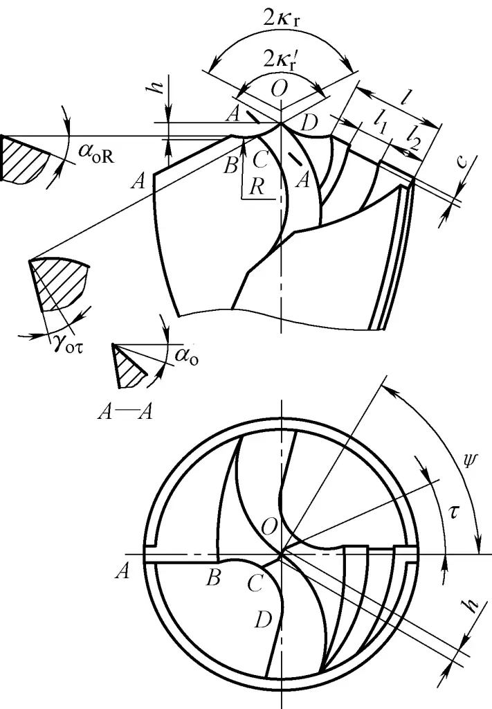
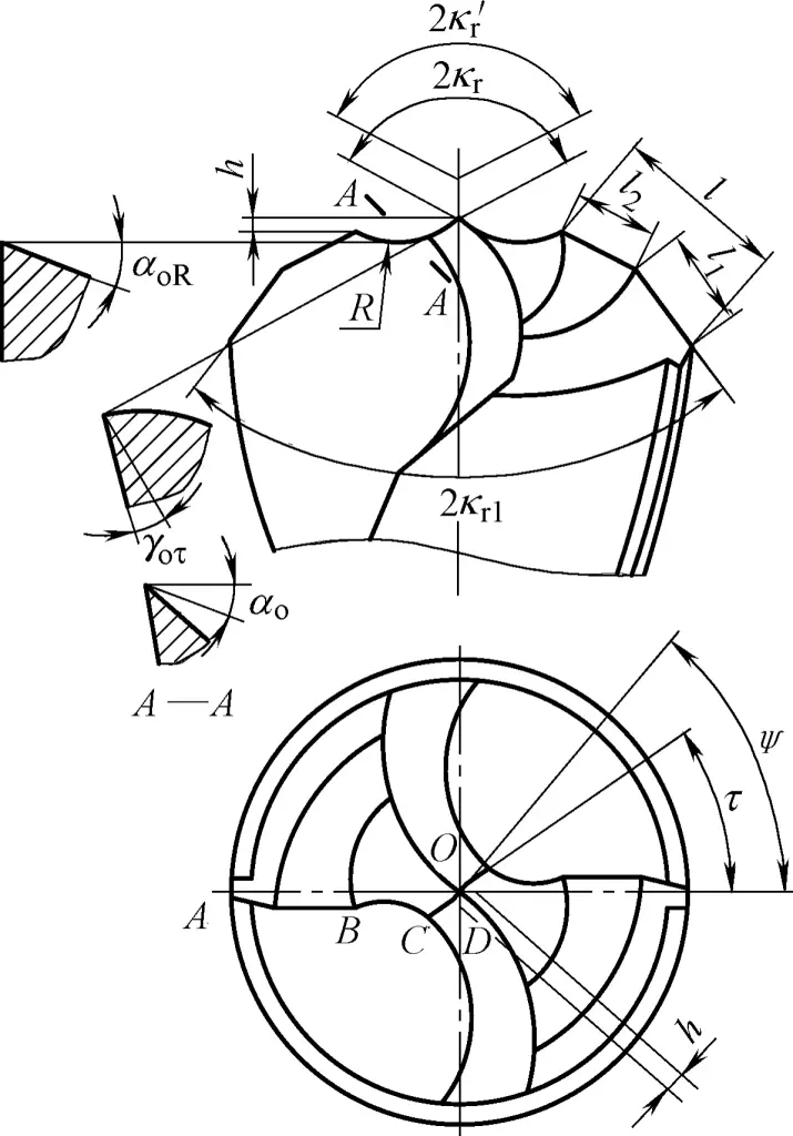
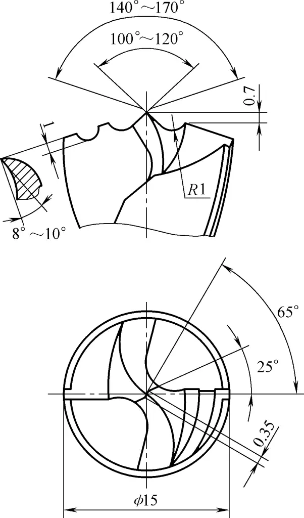
Figure 23 shows a basic gang drill of medium size (15≤d≤40mm). From the figure, it can be seen that the basic gang drill is a standard twist drill with added crescent-shaped grooves, modified chisel edge, and single-sided chip-breaking grooves. Its characteristics are:
1) Adding crescent-shaped grooves.
Forming a crescent-shaped arc edge is the most significant feature, which divides the main cutting edge into three sections: outer edge (AB section), arc edge (BC section), and inner edge (CD section). This is beneficial for chip breaking and chip removal, and the rake angle at each point on the arc edge is larger than before, making cutting smoother.
During drilling, the arc edge cuts a circular ring rib on the bottom of the hole, which can limit the swing of the drill and enhance centering. Since grinding the crescent-shaped groove lowers the height of the drill, the chisel edge can be ground sharper without affecting the strength of the drill point.
2) Modifying the chisel edge.
Shortening the chisel edge can reduce feed force and improve centering. At the same time, grinding the rake angle at the inner edge improves cutting ability.
3) Creating single-sided chip-breaking grooves.
That is, grinding a concave chip-breaking groove on one outer edge, which is beneficial for chip removal and reducing cutting force. The shape characteristics of basic gang drills are: “Three points and seven edges sharp at the front, crescent-shaped arc grooves on both sides, one side outer edge with an additional groove, chisel edge ground low, narrow and sharp.” Three points refer to the main cutting edge divided into three sections forming three points; seven edges refer to two outer edges, two arc edges, two inner edges, and one grooved edge.
Drill angles: 2kr =125°, 2k’r =135°, ψ=65°, τ=25°, γoτ =-15°, αo =10°~15°, αoR =12°~18°, l=(0.2~0.3)d, l 1 =l/4, l2 =l/2, R=0.1d, h=0.03d, b=0.03d, c=1.5f. Where: d is the drill diameter, f is the feed rate.
1) Dressing the grinding wheel.
For grinding on a common grinding machine, use white aluminum oxide (WA) or brown aluminum oxide (A) wheels, with grit size F46~F48 and hardness K~L.
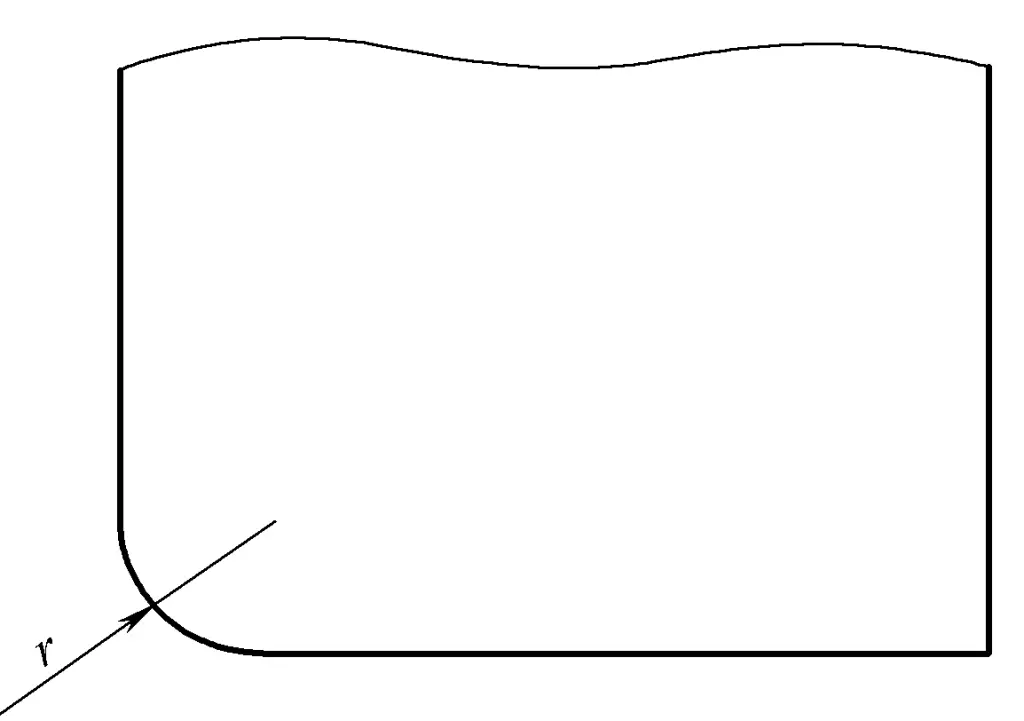
Use a diamond to flatten the outer circle and both sides of the grinding wheel (the grinding wheel should not wobble). Generally, the right side is close to a sharp angle, and the left side is ground into an arc. The radius of the rounded corner r is slightly smaller than the radius of the drill bit’s curved edge, as shown in Figure 24.
2) Grinding the main cutting edge.
The method is the same as grinding standard twist drills, controlling parameters 2k r and α o . The grinding method is shown in Figure 25.
3) Grinding the curved edge.
Control parameters: R, αoR , l, 2k’r , as shown in Figure 26. The grinding method is as follows:
4) Grinding the chisel edge.
Control parameters: τ, γo , bo . The method is similar to grinding the chisel edge of a standard twist drill, as shown in Figure 27.
The grinding method is as follows:
5) Grinding the chip-breaking groove on the single-sided outer straight edge.
The grinding method is shown in Figure 28. Choose a grinding wheel with a smaller diameter, position the side of the wheel perpendicular to the outer edge, with the grinding point roughly on the horizontal center plane of the wheel, centered on the outer edge.
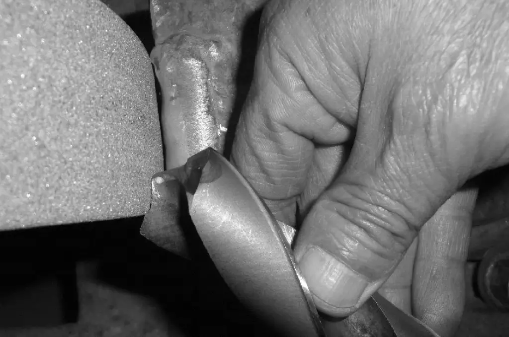
When grinding, swing the drill tail in the vertical plane as it contacts the grinding wheel, creating a chip-breaking groove with a certain relief angle. Thus, there are 14 grinding parameters for the basic group drill, including 7 length parameters and 7 angle parameters, as shown in Table 8.
Table 8 Basic group drill grinding parameters
| Grinding length | Grinding angle | ||
| Point height | 0.03d | Outer edge point angle | 2kr=125° |
| Curved radius | R≈0.1d | Inner edge point angle | 2k’r =135° |
| Outer edge length | When d>15mm, l=0.3d | Inner edge rake angle | Yoτ=-15° |
| When d≤15mm, l=0.2d | |||
| Groove spacing | l1=l/4~l/2 | Inner edge inclination angle | τ=20°~30° |
| Groove width | l2=l/3~l/2 | Chisel edge inclination angle | ψ=60°~65° |
| Groove depth | c=1~1.5f | Outer edge relief angle | αo=10°~15° |
| Chisel edge length | b≈0.03d | Curved edge relief angle | αoR=12°~18° |
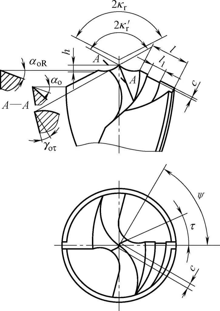
Due to the brittleness of cast iron, when drilling, the chips form in fragments mixed with powder, which get squeezed between the back of the drill bit, the edges, and the hole wall, causing intense friction and wear on the drill bit. Wear occurs almost entirely on the back surface, but the most severe wear is at the outer corner of the drill bit, significantly affecting its service life. Therefore, when grinding the drill bit, the following aspects should be considered.
1) To protect the drill point, grind a crescent-shaped curved groove to lower the drill center. After entering the workpiece, the three points quickly cut simultaneously, providing good centering. The drill point is less likely to chip and wear, and it’s easier to align.
2) Use a double point angle, grinding a chamfer at the outer edge of the drill bit to form a double point angle (2Kr1 ). This widens the corner area, improving heat dissipation conditions and thus increasing the lifespan.
3) Appropriately increase the relief angle, generally about 3° larger than when drilling steel, to reduce friction between the drill bit and the workpiece. The characteristics of the drill bit can be summarized as “Cast iron chips are like abrasives, use lower speed and higher feed, keep three cutting edges sharp with cooling, double point angle for longer life”.
The structural shape and geometric parameters of the drill bit are shown in Figure 29.
Drill bit angles: 2kr =120°, 2k’r =135°, 2K r1 =70°, ψ=65°, τ=25°, γoτ =-10°, αo =13°~18°, αoR =15°~20°, l=0.3d, l1 =l2 , R=0.12d, h=0.02d, b=0.02d (d is the drill bit diameter).
The structural shape and geometric parameters of the drill bit are shown in Figure 30. It can replace a reamer, or be used when the hole diameter is non-standard, to improve drilling accuracy and reduce hole wall surface roughness.
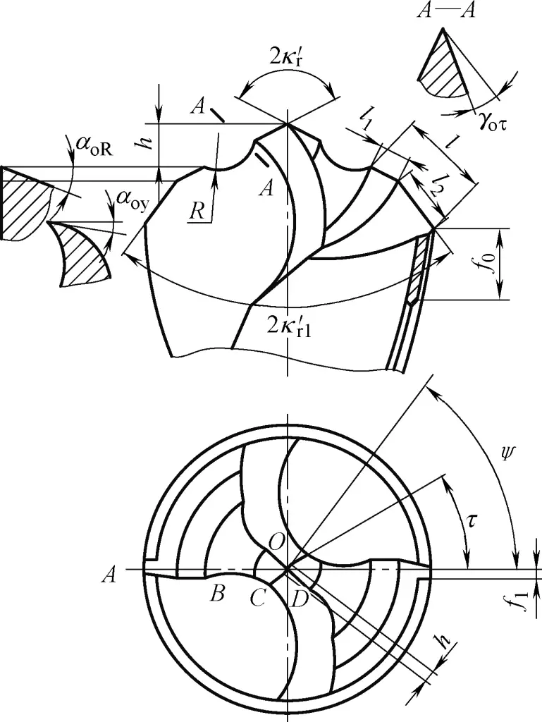
Drill bit angles: 2kr =15°~20°, ψ=80°, τ=25°, γoτ =-10°, αo =8°~12°, αoR =10°~15°, αoy =4°~6°, l=0.25d, l1 =0.2d, l2 =0.15d, R=0.1d, f0 =3~5mm, f1 =0.5mm, h=0.2d, b=0.02d (d is the drill bit diameter).
The main problem when drilling stainless steel holes is the difficulty in breaking chips. Although this material is not very high in strength, it has high plasticity and low thermal conductivity. When using basic group drills, increasing chip deformation to break chips will increase the cutting load and reduce the drill bit’s lifespan, which is undesirable.
Based on the basic group drill, increase the curved edge radius R, increase the point height h, and grind the curved edge and single-sided chip-breaking groove shallower. This increases the tool tip angle of the curved edge tip and chip-breaking edge tip. During drilling, the curling motion of the wide chip is used to twist and tear off the previously separated narrow and straight chip at the junction’s crack, which is a measure to fully utilize the cutting performance of the drill bit.
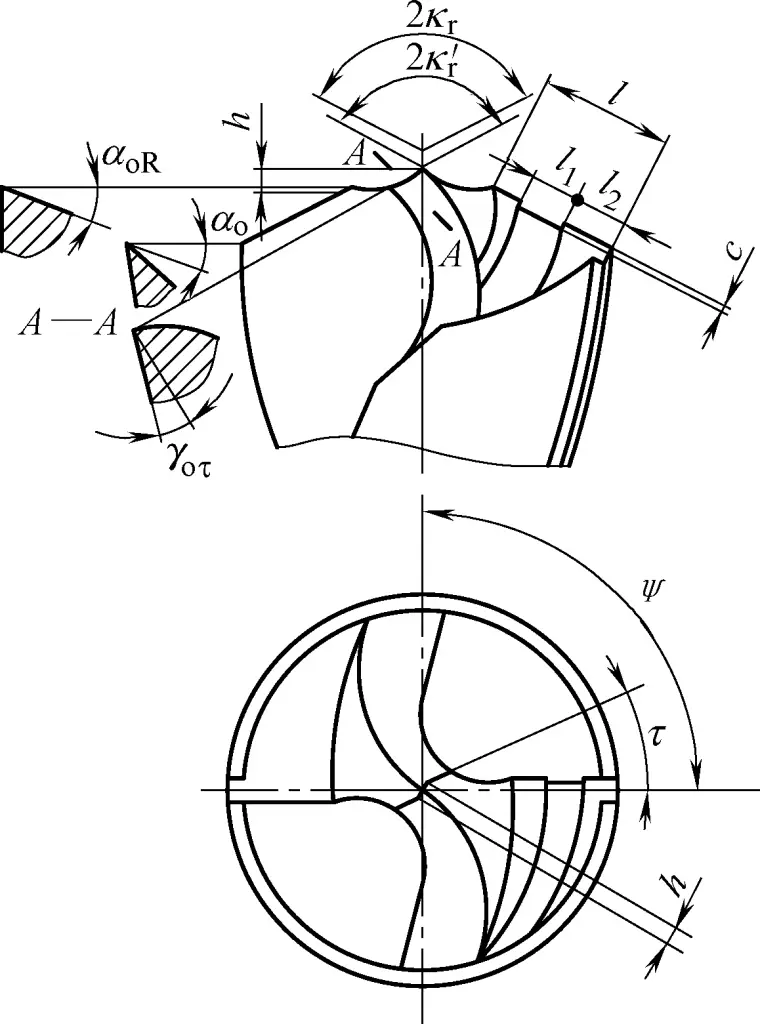
Drill bit angles: 2kr =135°~150°, 2k’r =135°, ψ=65°, τ=20°~25°, γoτ =-15°, αo =10°~12°, αoR =14°~16°, l=0.3d, l1 =l2 =l/3, R=0.2d, h=0.05d(2kr =150°)~0.07d(2kr =135°), b=0.04d (d is the drill bit diameter), c=f/3 (f is the feed rate).
The structural shape and geometric parameters of the drill bit are shown in Figure 31.
The structural shape and geometric parameters of the drill bit are shown in Figure 32. The main problem with drilling pure copper holes is that due to the soft material, it easily produces “stabbing” and causes the drill bit to vibrate, resulting in non-circular or polygonal holes.
Also, because it’s difficult to break chips, the chips wrap around the drill bit, causing the hole to enlarge externally, resulting in rough holes or torn hole walls. Since pure copper material conducts heat faster than high-speed steel drill bits, the drill bit can easily get stuck in the hole when drilling deeper holes. Therefore, when grinding the drill bit, the following aspects should be considered.
1) The shape of the drill core should be appropriate to ensure stable cutting and reliable centering. This mainly involves appropriately reducing the inner cutting edge angle 2k’r , increasing the drill point height h, making the inner cutting edge rake angle γ oτ slightly more negative, reducing the circular edge relief angle αoR , and setting the chisel edge inclination angle ψ=90°.
2) For drill bits with a diameter larger than 25mm, grind chip-breaking grooves on the outer cutting edge to facilitate chip removal and further reduce the cutting load.
3) Choosing an outer cutting edge angle 2kr =120° aims to facilitate chip removal and improve the surface quality of the hole wall (when drilling hardened pure copper, 2k r should be appropriately increased).
Drill bit angles: 2kr =120°, 2k’r =115°, ψ=90°, τ=30°-35°, γoτ =-25°, αo =12°-15°, αoR =10°-12°, l=(0.2-0.3)d, R=(0.1-0.2)d, h=0.06d, b=0.02d. For d≤25mm, no chip-breaking groove; for d>25mm (d is drill bit diameter), l1 =l2 /2, l2 =l/2.
The main problems with drilling aluminum alloy holes are severe built-up edge, rough hole walls, and difficulty in chip removal when drilling deep holes.
The geometric parameters of aluminum alloy drill bits are similar to those of basic type drill bits. However, the chisel edge is ground narrower to further reduce the cutting load and heat. When grinding the chisel edge, more of the flank is removed to increase chip space. The point angle 2k r is increased to make the narrow strips of chips curl upwards, reducing friction with the drill’s spiral grooves and facilitating chip removal.
The structural shape and geometric parameters of the drill bit are shown in Figure 33.
In addition to mechanical clamping methods, copper brazing and adhesive bonding are also used to connect carbide inserts to tool holders.
Copper brazing is generally used to braze carbide inserts onto turning tool holders. Due to the brittle nature and poor thermal conductivity of carbide inserts, they have a high shrinkage rate when heated. If the operating process is improper during brazing, large internal stresses can cause coarse and deep cracks, as shown in Figure 34.
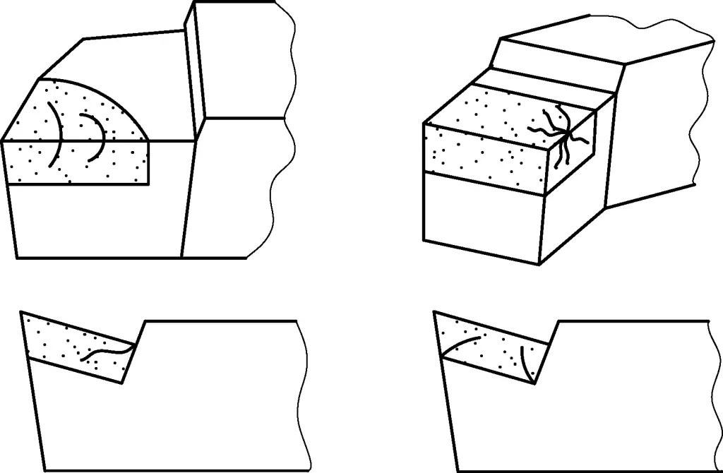
The cooling rate has a significant impact on the brazing quality, and rapid cooling can cause the insert to shatter. Brazed tools should be immediately subjected to low-temperature tempering (220-250°C), then placed in a dry insulating medium (such as charcoal powder, wood ash, asbestos powder, etc.) and kept warm for 6-8 hours to remove most of the brazing stress, prevent cracking in the insert, and improve the tool’s service life.
The heating rate during brazing also significantly affects the brazing quality. Rapid heating can produce large internal stresses, causing the insert to chip at the brazing layer due to excessive local thermal stress. Since carbide has low thermal conductivity and high sensitivity to rapid heating, heating during brazing must be slow.
The contact surfaces between the insert and the tool slot must be flat. Bumps, depressions, or scale will prevent good contact between the two, causing uneven distribution of brazing material, stress concentration, and cracking of the insert.
Additionally, the shape of the tool slot should match the insert, with dimensions not differing too much, and the insert’s overhang should not be too large. Otherwise, due to the tensile stress the tool undergoes during the brazing process and the different shrinkage rates of the insert and tool holder after thermal expansion, chipping may occur at the brazing layer of the insert.
For brazing large-sized inserts and those prone to cracking (such as YT30 inserts), a multi-layer brazing method can be used by adding a 0.4mm thick low-carbon steel sheet under the insert, as shown in Figure 35. This can eliminate stress caused by inconsistent shrinkage between the insert and tool holder during brazing, preventing insert cracking.
1—Insert
2, 4—Brazing material
3—Thin steel sheet
Multi-layer brazing is similar to ordinary brazing, but with an additional layer of low-carbon steel sheet. After brazing, the thickness of the brazing layer increases. Since the linear expansion coefficient of the steel sheet is smaller than that of the steel tool holder, the elongation rate of the brazing layer is reduced, while the thickness of the brazing material does not increase. Therefore, stress is reduced, strength is increased, which helps avoid insert chipping.
During brazing, when the brazing material melts, use a pointed rod to press the insert firmly. This is because the metal molecules diffuse between the insert and brazing material, and between the brazing material and tool slot, creating an adhesion stronger than the strength of the brazing layer material. Therefore, the brazing layer should be as thin as possible and uniformly continuous. If the brazing material is too thick, the brazing will not be solid.
At the same time, it should be noted that the tip of the pointed rod should not be too large, otherwise, it may cause the insert to crack due to sudden cooling when pressing.
When improper brazing operations can cause cracking in carbide inserts and reduce tool life, bonding is clearly superior to brazing.
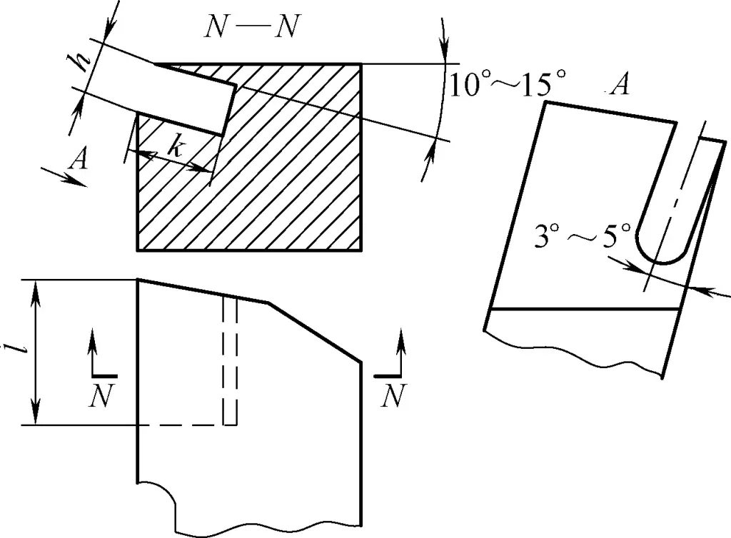
Bonding involves cutting an angled slot at the front end of the tool holder where the insert is to be fixed, and using inorganic adhesive to bond the insert in the slot. The bonding strength and the self-locking force generated during cutting maintain the rigidity of the connection between the insert and the tool holder.
Figure 36 shows the slotting situation before bonding a 90° external turning tool. The slot height h is 0.1-0.3mm greater than the insert thickness, l is approximately equal to the insert length, and k is approximately equal to the insert width. The surfaces inside the slot do not require smoothness, with a surface roughness Ra value in the range of 50-62μm being acceptable.
Copper oxide-phosphoric acid inorganic adhesive can be used for bonding. To prepare this inorganic adhesive, take 4.5g of copper oxide powder for every 1mL of phosphoric acid solution, and mix evenly on a copper plate.
Before bonding, first clean the carbide insert and tool slot with acetone and dry at room temperature. After bonding, leave it at room temperature for about 2 hours, applying pressure to fix it. Once it has initially solidified, place it in a heating furnace and keep it at 60-80°C for 3-4 hours.
If not handled properly during grinding, fine and irregular cracks are likely to appear on the insert.
When grinding a brazed carbide turning tool for the first time, first rough grind on a corundum wheel, especially removing the non-carbide material parts, then grind the carbide parts on a silicon carbide (green) wheel. This method is more efficient, produces better grinding quality, and reduces the probability of damage to the carbide insert.
When grinding manually, apply appropriate pressure to the rotating wheel, not too much, and avoid grinding in one spot for a long time. Interrupt frequently to allow more cooling time for the tool. If the temperature on the tool gets too high, causing uneven heating and cooling, the insert is prone to cracking.
During grinding, do not apply excessive force. Otherwise, increased friction will cause the insert temperature to rise sharply, creating localized high temperatures, forming additional thermal stress leading to thermal deformation, and producing overheating cracks.
When a newly welded carbide lathe tool or severely worn lathe tool needs sharpening, it should first be rough ground on a coarse grinding wheel, then fine ground on a fine grinding wheel. The grinding wheel material should be medium-hard green silicon carbide. For rough grinding, use abrasive grits F40 to F60; for fine grinding, use grits F80 to F100; for grinding tool shanks, use grits F36 to F46.
When sharpening manually, coolant may not be necessary. However, avoid immersing the hot, dry-ground tool in cold water to reduce temperature, as this can cause severe cracking in the tool due to sudden temperature changes and excessive contraction stress.
When using machine sharpening (such as on a tool grinder), the axial runout and radial runout of the grinder spindle should not be too large. Otherwise, vibration or instability may occur during grinding, causing the tool insert to develop vibration cracks or fine chipping at the cutting edge.
When sharpening carbide tools to prevent cracking, it is recommended to use a negative rake grinding method for rough grinding. This involves first grinding a negative chamfer before grinding the front and back faces of the lathe tool. After the front and back faces and chip breaker groove are ground, the negative chamfer can be fine-tuned as needed (Figure 37). This method can improve tool insert strength, enhance vibration resistance during grinding, and reduce grinding heat on the guide insert.
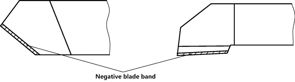
During grinding, the temperature rises rapidly, but the tool insert has a small heated area and limited heat capacity. The large temperature difference between the insert and the tool holder causes concentrated thermal stress, leading to cracking in the insert. When using the negative rake grinding method, the negative rake band on the cutting edge enhances the insert’s ability to withstand impact loads and increases the heated area, effectively preventing crack formation.
There are no strict rules for the shape and size of the negative rake band. It can be determined based on the grinding allowance and tool dimensions. The negative rake band can be ground off during fine grinding to achieve the final profile dimensions.
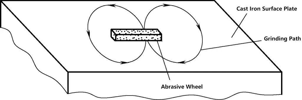
Generally, when lathe tools become dull, they are resharpened manually on a grinding machine. In production lines and when conditions allow, specialized devices can be used for grinding lathe tools. Figure 38 shows a simple device used for grinding welded lathe tools. Part 1 is a disc installed in the base (not shown in Figure 38). The disc can rotate around its axis according to the scale markings on its perimeter.
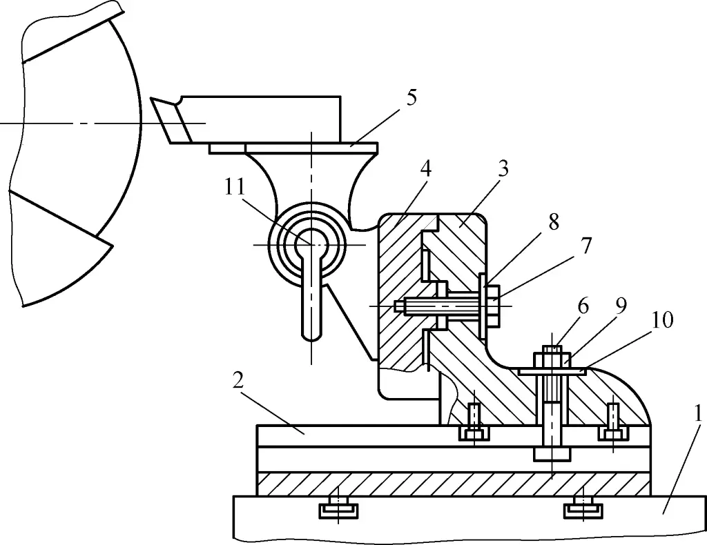
1—Disc
2—Sliding plate
3—Support
4—Bracket
5—Tool holder
6—Bolt
7, 11—Screws
8, 10—Washers
9—Nut
When grinding the main approach angle and end cutting edge angle of the lathe tool, the angle is controlled by rotating the disc. Part 2 is a sliding plate, which is fixed to disc 1 using hex socket screws. When these screws are loosened, sliding plate 2 can move longitudinally on disc 1.
Part 3 is a support, which is tightly fastened to sliding plate 2 using bolt 6, nut 9, and washer 10. It can move laterally on sliding plate 2. Part 4 is a bracket that fits with support 3 and is secured with screw 7 and washer 8. The bracket has degree markings. Part 5 is the tool holder, fixed to bracket 4.
When grinding the relief angle of the lathe tool on the side of the grinding wheel, loosen screw 7 and turn bracket 4 to adjust. To grind the relief angle, release the handle to loosen screw 11, and rotate tool holder 5 to adjust. This device has a simple structure, provides accurate grinding angles, and is suitable for centralized grinding operations.
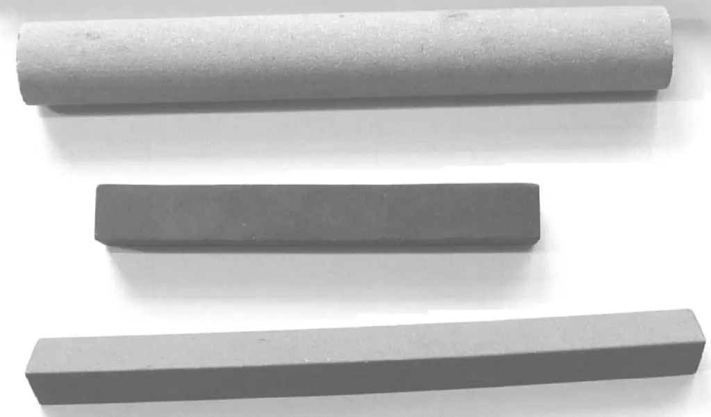
Lathe tool honing is generally done manually using honing stones. Practice has shown that honing stones are suitable for almost all types of tools, including high-speed steel and carbide tools, as well as both roughing and finishing lathe tools. Figure 39 shows commonly used honing stones for honing lathe tool cutting edges.
(1) Selection and “Opening” of Honing Stones
Honing stones have similar characteristics to grinding wheels. For honing high-speed steel and carbon tool steel cutters, choose alumina-based honing stones; for carbide tools, choose green silicon carbide honing stones. Rectangular bar-shaped honing stones are preferable.
It should be noted that newly acquired honing stones should not be used directly to hone tools. This is because honing stones are formed through high-temperature sintering, and deformation is difficult to avoid, especially in thinner and longer stones. Additionally, like sintered grinding wheels, the abrasive grains in newly sintered honing stones are round and have not been “opened,” as shown in Figure 40.
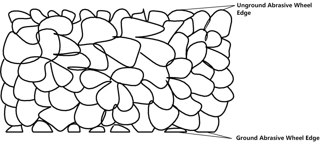
If used without “opening,” the honing stone will lack cutting ability, resulting in slipping during honing and poor straightness and flatness of the honed cutting edge.
To “open” a honing stone, generally use F80 to F100 grit green silicon carbide abrasive as the grinding agent, with kerosene or diesel oil as the grinding fluid. Hand-grind the stone on a flat plate in a figure-8 or circular pattern, as shown in Figure 41.
Do not apply too much pressure when grinding. For round honing stones, lightly press with your fingers and roll the stone on the flat plate, observing until all areas have been ground evenly.
A well-ground honing stone will feel noticeably different from before grinding, with a clearly perceptible sharp “cutting edge.” Additionally, honing stones that have been used for a long time, have surface scratches, or show uneven wear should be resurfaced promptly to avoid affecting the honing quality of lathe tools.
Due to the influence of grinding wheel grit size and runout on grinding machines, the ground surfaces and angles of lathe tools may be inaccurate and have high surface roughness. Use a coarse-grit honing stone for initial rough honing, followed by a fine-grit honing stone for finishing.
When honing, the honing stone should be pressed firmly against the surface being honed and moved in short, reciprocating motions. The stroke should not be too large to prevent unevenness in the honed surface. Continue honing until the grinding wheel marks disappear. When honing the chip breaker groove, choose a round honing stone of an appropriate diameter. For other profiles, rectangular honing stones can be used.
Special attention should be paid when honing the tool’s flank face. Since the flank face of a lathe tool is ground as a curved surface on the outer diameter of the grinding wheel, the honing principle should be to maintain this curved surface and only hone the cutting edge portion, as shown in Figure 42.
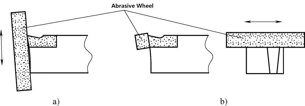
a) Incorrect honing method
b) Correct honing method
The chamfer, transition edge, and wiper edge of the lathe tool can all be directly honed using honing stones.
For complex shaped tool cutting edges, in addition to using honing stones, diamond files can be used to shape the cutting edge. For example, small radii and complex cutting edges that are difficult to grind directly by hand on a grinding wheel can be shaped using diamond files.