How to Calculate Sheet Metal Weight: Essential Formulas
Ever wondered how to quickly calculate the weight of sheet metal? This article unveils a simple formula that takes the…
Imagine a factory floor where precision meets efficiency: the realm of automated stamping machines. These mechanical marvels revolutionize production lines, ensuring each part is flawlessly crafted at lightning speed. But what exactly makes this equipment indispensable in modern manufacturing? In this article, we’ll uncover the key components and technologies behind automated stamping, revealing how they enhance productivity and maintain impeccable quality. Get ready to explore how these machines transform raw materials into finely detailed products with unmatched consistency and speed.

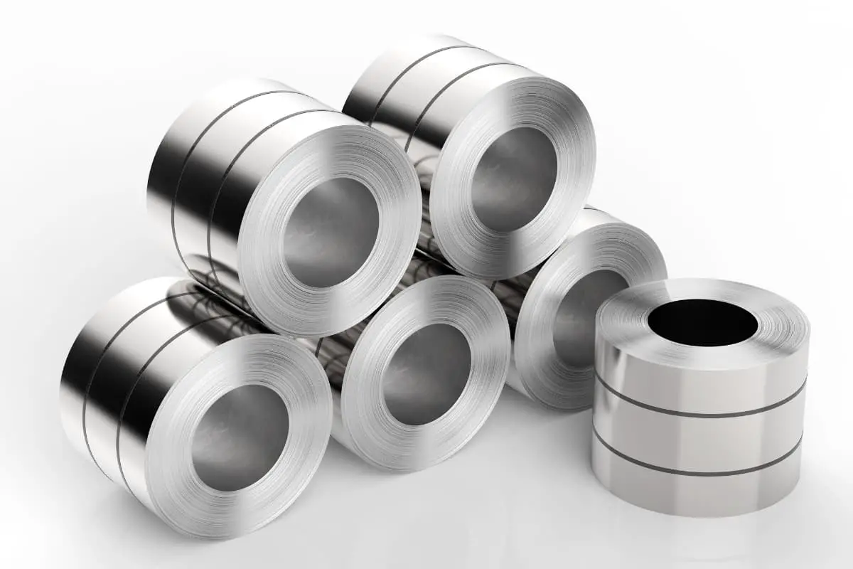
In automatic stamping production lines using coil materials, the production line should be equipped with an uncoiler or uncoiler-leveler to uncoil, level, longitudinally or transversely cut the sheet material, processing it into the required blank shape, such as strips, blocks, or other shapes.
Uncoiler and leveler are suitable for uncoiling and leveling various cold and hot-rolled sheet metals. They are easy to operate, simple, have a wide range of applications, and are indispensable sheet metal blanking equipment in the metal forming field.
Table 1 lists the basic parameters of sheet metal uncoiling, leveling, and cutting production lines.
Table 1 Basic Parameters of Sheet Metal Uncoiling, Leveling, and Cutting Production Lines
| Coil thickness/mm | Coil width series/mm | Production line speed/(m/min) | Coil inner diameter series/mm | Maximum coil weight/kg | Maximum coil outer diameter range/mm | Cutting length/mm | ||
| Transverse cutting | Longitudinal cutting | |||||||
| Flying shear | Stop-and-cut | |||||||
| 0.15~0.6 | 450 650 800 1000 1300 1600 1800 2000 2200 | 50~120 | 15~60 | 30~200 | 450 508 610 762 | 15000 | 1000~2200 | 500~4000 |
| 0.3~1.2 | ||||||||
| 0.5~2.0 | 20000 | |||||||
| 0.8~3.0 | ||||||||
| 1~4 | 40~80 | 15~50 | 30~150 | 1000~16000 | ||||
| 2~8 | ||||||||
| 3~12 | 20~60 | 10~40 | 40000 | |||||
| 4~16 | ||||||||
| 6~20 | ||||||||
| 8~25.4 | ||||||||
Note: The parameters in the table are calculated based on coil material mechanical properties σs ≤245MPa, Rm ≤460MPa.
Figure 1 shows an automatic wide coil uncoiling and blanking line manufactured by a German company. The wide coil is hoisted by a crane with a special hook onto the coil feeding device 1, clamped on the uncoiling devices 2 and 3 for uncoiling.
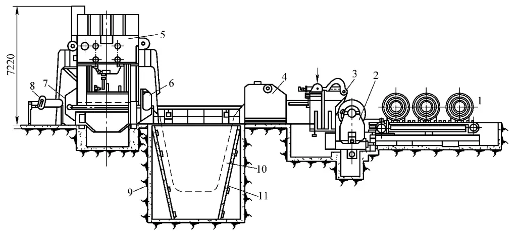
1—Coil feeding device
2, 3—Uncoiling devices
4—Multi-roll leveler
5—Blanking press
6, 7—Automatic coil pulling and pushing feeding mechanism
8—Scrap cutting device
9—Compensating loop pit
10—Coil compensating loop
11—Gantry frame
The coil enters the multi-roll leveler 4 for leveling, passes through the coil compensating loop 10, then enters the automatic coil pulling and pushing feeding mechanism 6, 7, and finally reaches the blanking press 5 for blanking. The cut blanks slide into the stacking device. When the end of a new coil has not yet entered the automatic pulling and pushing feeding mechanism, the gantry frame 11 installed on both sides of the compensating loop pit 9 immediately lifts the coil end and feeds it into the automatic pulling and pushing mechanism.
The automatic coil pulling and pushing feeding mechanism needs to be synchronized with the blanking press and intermittently feed the coil, while the uncoiling device and leveler continuously feed the coil. The operating speed between the two is adjusted by a photoelectric control system.
Based on the feedback signal output from blanking sampling, it is sent to the computer control system to control the continuous feeding speed, thus forming a closed-loop control system. The coil connecting the uncoiling device and the leveler relies on the compensating loop in the pit for storage and compensation.
The use of automatic feeding devices is a basic requirement for achieving automation in stamping production. It is the main content of stamping automation, directly affecting stamping productivity, production rhythm, and the overall automation level of stamping production. It can also significantly improve the utilization rate and productivity of the press.
Based on different power sources, feeding mechanisms for ordinary presses can be divided into three categories: mechanical, hydraulic, and pneumatic. In stamping processes, mechanical and pneumatic types are more commonly used. Pneumatic feeding mechanisms have advantages such as being agile and lightweight, versatile, adjustable in feed length and material thickness, and quick response.
Due to the use of differential pressure pneumatic working principle, pneumatic feeding mechanisms generate relatively high working noise, which can affect the stamping work environment. They are mainly used for preliminary feeding in stamping and small batch, multi-variety production.
Although mechanical feeding mechanisms are relatively difficult to adjust and have larger dimensions, they have advantages such as accurate and reliable feeding, less impact and vibration, low noise, and good stability. They remain the most commonly used automatic feeding method in stamping processes.
Currently, there are two widely used configuration methods for stamping production lines: One method is to install a roller feeding machine (or pneumatic feeding machine) on a single-point press, which can achieve continuous stamping for single or multiple processes with good operational performance; The other method is to install a multi-station feeding device on a double-point press, combined with uncoiling devices, leveling devices, etc., to form a multi-station continuous stamping production line.
As these two feeding mechanisms significantly reduce floor space and inter-process transportation, their application in production is showing an increasing trend.
A multi-station feeding system is a device similar to a moving arm, whose main function is to move stamped parts from one station to another. Each set of dies within a group of dies completes the stamping work in the same press.
The multi-station feeding moving bar is the main structural component, moving along the die area, with end effectors for moving stamped parts installed on these structural components. For automotive body stamping, based on the feeding transmission method, multi-station feeding systems mainly include mechanical feeding, electronic servo feeding, and combined feeding systems.
This system moves stamped parts from one station to another through direct connection with the press transmission system. The power output device on the press crossbeam transfers energy from the top of the press to the ground, and a large mechanical cam installed on the feeding mechanism is driven by a follower, with the cam rotation driving the mechanical feeding action.
It is relatively reliable in use, but has disadvantages: mechanism wear can affect feeding accuracy; once the mechanical transmission design specifications are determined, they cannot be changed; as the size of processed parts increases, the transmission mechanism will also increase, shortening the expected lifespan of mechanism components.
This system is driven separately by servo motors, connected to the feeding system through gearboxes and drive shafts, and operates under computer control. Coordination with the press action is achieved through electronic signals exchanged between the press and the controller.
Its motion trajectory is determined by computer programs, offering good flexibility and the ability to provide any feeding distance, clamping stroke, closing stroke, and lifting stroke according to the workpiece requirements.
Compared to mechanical feeding, electronic servo feeding has the following advantages: no need to use the press’s power output device; programmable stroke trajectories for each axis (including stroke length and time curve); micro-adjustments can be made to the feeding device without adjusting the slide position; faster acceleration and deceleration; fewer mechanical parts resulting in lower failure rates, etc.
This device consists of a feeding hook, a non-return pin, and a driving mechanism.
This device consists of one or more pairs of rollers and a driving device. It has a simple structure and good versatility, making it the most widely used form currently. It can be used for both coil and strip materials, suitable for different thicknesses and pitches.
Based on the installation form of the rollers, roller-type feeding can be divided into vertical rollers and horizontal rollers. Horizontal rollers include single-sided and double-sided types, with single-sided horizontal rollers generally being push-type, and a few being pull-type, while double-sided horizontal rollers are in a push-pull form.
Roller-type feeding devices have various driving methods, common ones include linkage four-bar mechanism transmission, rack and pinion transmission, arc tooth bevel gear transmission, inclined wedge transmission, and sprocket transmission. There are also pneumatic and hydraulic drives, with power sources divided into independent energy systems and those from the equipment’s main shaft.
Figure 2 shows a single-sided push-type horizontal roller feeding device. The material is fed through upper and lower rollers 6. The adjustable eccentric disc 1 installed at the end of the crankshaft drives the pawl to oscillate back and forth through the connecting rod 3, intermittently pushing the ratchet wheel 4 to rotate. The ratchet wheel is installed on the same shaft as the roller, producing intermittent feeding. The scrap after stamping is rewound by the spool 7. The conveyor belt tension should not be too high to avoid slipping.
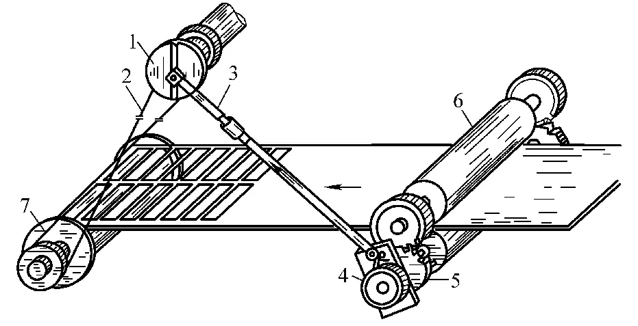
1—Adjustable eccentric disc
2—Conveyor belt
3—Connecting rod
4—Ratchet wheel
5—Gear
6—Roller
7—Spool
This device is mainly used for conveying sheet or block-shaped parts.
The gate-type feeding device has a simple structure, is safe and reliable, and has high feeding accuracy. It has been widely used in production, as shown in Figure 3. The gate-type feeding device requires that the thickness of the blank should not be too small, generally greater than 0.5mm, and the surface of the blank should be flat with no large burrs on the edges, otherwise it will affect the reliability of the feeding device’s operation.
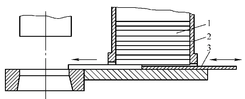
1—Sheet or block-shaped parts
2—Feed box
3—Push plate (gate)
When the distance between the magazine and the working part of the mold is large and the press slide stroke is small, multiple strokes feeding can be considered. This means pushing the workpiece in stages or pushing workpieces during the feeding process, with only the last workpiece being pushed by the pusher plate.
This device consists of a swing arm, gripping part, and driving part, utilizing the swing of the arm to achieve gripping and feeding processes.
This device consists of clamps, connecting rods, sliding plates, feed troughs, and stacking parts, mainly used for feeding round block materials.
The transmission forms of this feeding device include friction type, ratchet type, slotted wheel type, worm gear type, and cylindrical cam type.
This device consists of clamping plates, clamps, longitudinal feeding mechanism, and transverse clamping mechanism. In multi-station stamping production, automatic feeding is divided into two-way and three-way feeding.
The two-way feeding method follows the “clamp-feed-release-return” pattern, with limitations on stamping methods and shapes of stamped parts; the three-way feeding method adds “up-down” movements to the two-way feeding method, allowing the clamping plate to operate in a “clamp-rise-feed-descend-release-return” pattern, expanding the range of products that can be processed by multi-station devices.
The function of the ejection mechanism is to promptly remove the stamped workpieces or waste materials, otherwise they will accumulate around the mold, affecting the normal operation of the feeding mechanism. According to transmission characteristics, ejection mechanisms can be divided into pneumatic and mechanical types.
Pneumatic ejection devices mainly include compressed air blowing and air cylinder piston pushing. Compressed air blowing devices are simple in structure and widely used for ejecting small stamped parts, but the position and orientation of the blown-out workpieces cannot be controlled, and they are relatively noisy.
Figure 4 shows another type of pneumatic ejection device, which uses the pushing force of the air cylinder piston to eject the workpiece from the mold. The cylinder operation is controlled by a cam mounted on the slide or crankshaft end through an air valve.
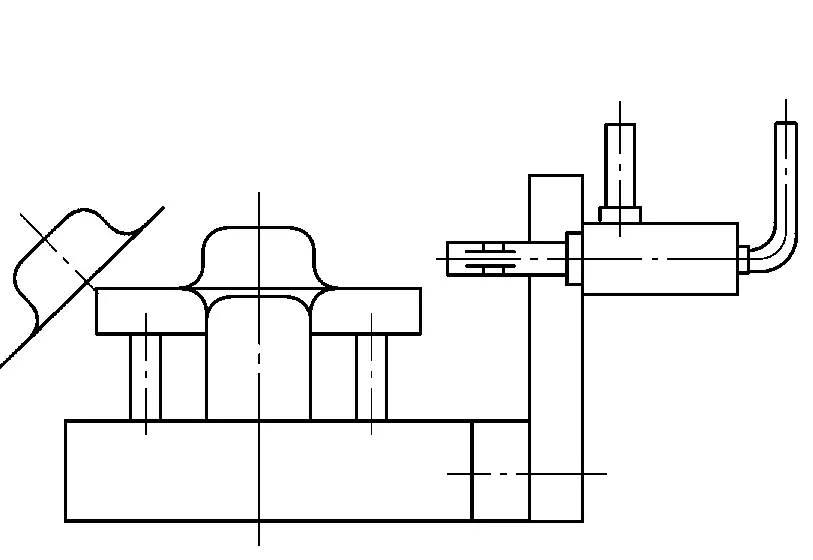
When the stamping work is completed and the slide moves upward, the cam controls the air source through a limit switch, allowing air to enter the left chamber of the cylinder, pushing the piston to the right, and the right end of the piston rod pushes the workpiece out from the right side. When the slide moves downward, the cam on the slide controls the air valve through a limit switch, allowing air to enter the right chamber of the cylinder, pushing the piston rod to the left, away from the stamping work area.
There are many structural forms, including tray-type, spring-type, and support rod-type.
Figure 5 shows a mechanical tray-type ejection mechanism, consisting of rod 3, receiving tray 5, and lower swing rod 6. The upper end of rod 3 is connected to the upper die. The receiving tray 5 and lower swing rod 6 are welded together, maintaining an angle β after welding; rod 3 and lower swing rod 6 are hinged, with the receiving tray aligned with the upper die.
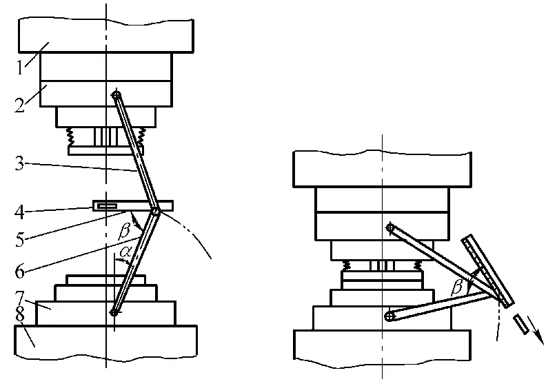
1—Press slide
2—Upper die
3—Rod
4—Workpiece
5—Receiving tray
6—Lower swing rod
7—Lower die
8—Worktable
The operation process is as follows: When the press slide rises with the upper die, the workpiece also rises with the upper die. Rod 3 is driven by the upper die, causing the lower swing rod 6 to swing upward, reducing angle α, and placing the receiving tray in a horizontal position. The workpiece falls onto the receiving tray pushed by the ejector rod.
When the slide moves downward, the lower swing rod 6 swings downward, causing the receiving tray to swing outward. Because the angle between the receiving tray and the lower swing rod is fixed at β, when the lower swing rod swings to the lowest position, the receiving tray has a larger tilt angle, allowing the workpiece to slide down automatically.
Since their introduction in the early 1960s, robots have developed over many years and are now widely used in various industries. For example, entertainment robots, service robots, underwater robots, military robots, humanoid robots, agricultural robots, medical robots, welding robots, handling robots, etc., have become an inseparable part of modern life, especially in manufacturing.
Robotics technology is a comprehensive and interdisciplinary high-tech field formed by the integration and intersection of multiple disciplines such as mechanics, mechanism theory, mechanical design, automatic control, sensor technology, electro-hydraulic-pneumatic drive technology, computer science, artificial intelligence, and bionics.
As a typical mechatronic equipment with high automation and intelligence, robots can automatically complete target operations or mobile tasks through computer programming, with high reliability, flexibility, and enormous information storage, processing capabilities, and rapid response capabilities. The research of manipulators, as an important branch of robotics research, has great practical value and strategic significance in modern manufacturing.
The earliest manipulators were often specialized with fixed programs or simple variable programs. These manipulators were mostly designed and manufactured for specific production sites, using pneumatic, hydraulic, or electrical drives, with limit switches, mechanical stops, or other sensors to control their working positions.
They have single working objects, fewer actions, simple structures, and low costs. The motion characteristics of simple manipulators mainly include arm movement and hand grasping and releasing actions.
As shown in Figure 7-56, assuming the initial motion state of the manipulator is at position one in the figure, it first locates to position one; then the forearm 3 brings the wrist 2 and hand 1 down to grasp the workpiece; next, the forearm 3 rises; after that, the upper arm 4 moves to the right while the column 5 rotates to position two, the forearm 3 brings the wrist 2 and hand 1 down to release the workpiece; finally, the manipulator returns to its initial position. This completes one work cycle.
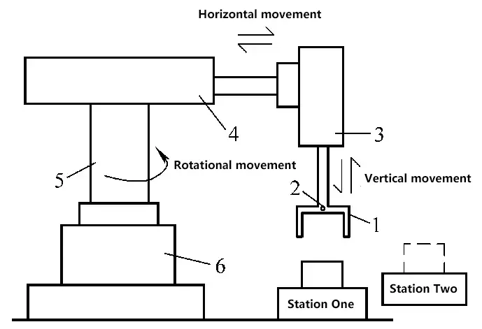
1—Hand
2—Wrist
3—Forearm
4—Upper arm
5—Column
6—Frame
Stamping manipulators are equipment specially developed based on manipulators to achieve stamping automation according to the characteristics of stamping production. They can replace manual work in various stamping stations for auxiliary stamping, handling, loading and unloading, etc. Figure 7 shows the structure of an automatic feeding manipulator for a cylindrical coordinate press.
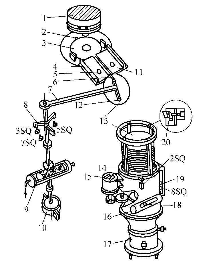
1—Punch
2—Locating pin
3—Lower die
4—Slide
5—Permanent magnet
6—Feeding claw
7—Arm
8—Bumper
9—Rotary air cylinder
10—Brake
11—Non-return stop block
12—Suction cup
13—Workpiece
14—Lifting platform
15—Rapid descent motor
16—Pawl air cylinder
17—Lifting air cylinder
18—Pawl
19—Stroke stop block
20—Separating claw
The feeding manipulator consists of an arm 7, suction cup 12, feeding claw 6, gear shaft, brake cylinder, etc. The piston rack of the cylinder drives the gear shaft to rotate, realizing the arm rotation of the feeding manipulator.
When the arm 7 of the feeding manipulator retracts above the lifting platform 14, the bumper 8 triggers the limit switch 7SQ, and the lifting cylinder 17 and pawl cylinder 16 act simultaneously. The pawl 18, ratchet wheel, lead screw, and nut raise the lifting platform 14.
As the lifting cylinder 17 rises, the material in the storage basket is immediately firmly sucked by the suction cup 12 of the feeding manipulator. During the ascent, it triggers the limit switch 8SQ to send a signal, causing the lifting cylinder 17 to descend and return to its original position; and triggers the upper limit switch 2SQ to send a signal, causing the feeding manipulator to return to the slide 4.
The feeding claw 6 connected to the suction cup frame of the feeding manipulator pushes the material (from the previous feed) on the slide onto the lower die face of the press, while the bumper 8 on the arm 7 triggers the limit switch 3SQ and sends a signal, opening the switch valve of the suction cup, connecting the suction cup 12 to the atmosphere. The sucked workpiece falls onto the slide and is held by two permanent magnets 5 to prevent the workpiece from being carried back by the feeding claw 6.
At the same time, the limit switch 3SQ de-energizes the intermediate relay, and after the directional valve changes direction, the feeding manipulator rotates in the opposite direction. When it rotates 30°, it touches the limit switch 5SQ and sends a signal to perform one stamping action.
When the feeding manipulator rotates back to its original position (i.e., back above the lifting platform 14), the bumper 8 triggers the limit switch 7SQ and sends a signal, and the feeding manipulator repeats the above actions.
As the arm of the feeding manipulator rotates back towards the lifting platform, when it reaches the limit position, a brake 10 (i.e., a mechanical braking device) is used to slow down the arm to reduce impact. The brake only provides unidirectional cushioning and braking for the arm rotation of the feeding manipulator.
When the arm turns towards the lifting platform, the brake installed on the gear shaft is released, and the rotation speed of the arm gradually increases, giving the feeding claw 6 enough kinetic energy to push the material to the die face of the press.
This automatic feeding manipulator device can be used on 600-1000kN presses. On general presses, by modifying the press crankshaft and adding feeding manipulator, lifting platform, and slide devices, the press can work automatically and continuously, ensuring rhythmic and safe production of the press, which is simple and convenient.
Stamping manipulators mainly consist of three major parts: the execution mechanism, driving mechanism, and control system.
Also known as the operator, it is the mechanical entity that completes the robot’s functions, with capabilities similar to a human arm. It can generally be divided into four parts: end effector, wrist, arm, and base.
1) End effector.
The end effector of a stamping manipulator usually has a gripping function and is therefore also called the hand part. The part that directly contacts the stamped workpiece and completes the corresponding operation is called the finger.
According to the different gripping methods and principles, the hand part can be divided into four categories: clamp type, air suction type, magnetic suction type, and ring type. The most common are clamp-type and suction cup-type hands. The hand part often adopts a modular design for easy installation and disassembly, which also improves the adaptability of the manipulator.
2) Wrist.
The wrist is used to support and adjust the position and speed of the end effector. The presence of the wrist can expand the range of motion of the arm, generally having 2 to 3 rotational degrees of freedom to adjust the posture of the end effector. Some robotic hands may not have a wrist structure and directly connect the end effector to the forearm.
3) Arm.
Usually composed of multiple rods and joints at the connections, it is connected to the main power source of the system, transmits power, and cooperates to adjust the posture of the end effector and wrist.
The arm often has multiple sections, and each section can have multiple segments. Usually, the section closest to the end effector is called the forearm, while the one closer to the base is called the upper arm. The upper arm is also connected to the base by joints to expand the overall range of motion of the robotic hand and enhance its flexibility.
4) Base.
It is the relatively fixed basic component in the robotic hand that bears the forces from the end effector, wrist, and arm. It can be divided into two types: fixed and mobile.
The fixed type cannot move freely and often performs fixed-position operations at close range, while the mobile base has wheels, tracks, or other mobile mechanisms installed at the bottom, allowing the robotic hand to move relatively freely. Since the functions of stamping robotic hands are usually quite simple, they generally do not need to have all the components.
The drive mechanism provides power and motion for the robotic hand, consisting of power source, transmission device, detection elements, etc. Common drive methods include electric motors, hydraulic and pneumatic devices, or a combination of two of the three.
As can be seen from Table 2, the pneumatic method has the lowest cost, the hydraulic transmission method has the largest transmission force, the electric motor transmission method has the highest precision and best control performance, and the mechanical transmission method is used less often and is generally not considered.
Table 2 Comparison of drive methods
| Item | Pneumatic transmission | Hydraulic transmission | Electric motor transmission | Electrical transmission | Mechanical transmission |
| System structure | Simple | Complex | Complex | Complex | Relatively complex |
| Installation flexibility | Large | Large | Large | Medium | Small |
| Output force | Slightly large | Large | Average | Small | Slightly large |
| Positioning accuracy | Average | Average | High | Very high | High |
| Action speed | Fast | Slightly fast | Fast | Fast | Slow |
| Response speed | Slow | Fast | Fast | Fast | Medium |
| Cleanliness | Clean | Possible contamination | Clean | Clean | Relatively clean |
| Maintenance | Simple | More complex than pneumatic | Complex | Complex | Simple |
| Price | Average | Slightly high | High | High | Average |
| Technical requirements | Relatively low | Relatively high | High | High | Relatively low |
| Control flexibility | Large | Large | Large | Medium | Small |
The control system usually includes two parts: sensor circuits and a central control unit (PC, PLC, and microcontroller, etc.) and its control circuits. It can respond to manual device operations (start-up, shutdown, and teaching, etc.) while controlling the robot to act according to specified requirements.
Commonly used control methods include open-loop control without feedback signal detection and closed-loop control with feedback signal detection.
Regarding the classification of robotic hands. Currently, there are many classification methods for stamping robotic hands, which can be categorized by usage range, drive method, purpose, coordinate form, control method, carrying capacity, motion trajectory, etc.
Can be divided into dedicated robotic hands, general-purpose robots, and teaching-type robotic hands.
1) Dedicated robotic hands.
This type of robotic hand is usually designed based on a specific mechanical site, producing specific actions under the guidance of fixed programs or simple variable programs. It has a single work object, fewer actions, simple structure, and lower cost.
2) General-purpose robots.
These are programmable general-purpose robotic hands that can adapt to different work objects, have strong versatility, and are suitable for flexible manufacturing systems characterized by multi-variety, small and medium batch production.
3) Teaching-type robotic hands.
Also known as teach-and-playback robotic hands, they learn by manually guiding the end effector (gripper, tool, welding gun, etc.) of the robotic arm, or by manually operating a simulation device or using a teaching pendant to make the robot memorize the expected actions, and then repeat and reproduce the operation program stored through teaching programming.
Can be divided into mechanical robotic hands, hydraulic robotic hands, pneumatic robotic hands, and electric robotic hands, etc.
Can be divided into stamping robotic hands, welding robotic hands, surface coating robotic hands, loading and unloading robotic hands, assembly robotic hands, non-destructive testing robotic hands, and medical robotic hands, etc.
Can be divided into point-to-point control robotic hands and continuous trajectory control robotic hands.
1) Point-to-point control robotic hands.
This is a point-to-point control method, which accurately controls the position and posture of the robot’s end effector at key points (target points) to complete the predetermined operational requirements. For example, loading and unloading handling robots and spot welding robots belong to the point-to-point control type of robotic hands.
2) Continuous trajectory control robotic hands.
This type of robotic hand coordinates the movement of various parts, precisely controlling the robot’s end effector to move along a predetermined trajectory and speed, and can control the posture of the end effector at each point along the curved trajectory. Arc welding, painting, and inspection robotic hands all belong to the continuous trajectory control method.
Can be divided into micro robotic hands, small robotic hands, medium robotic hands, and large robotic hands, etc.
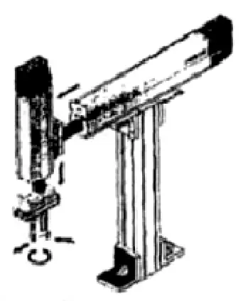
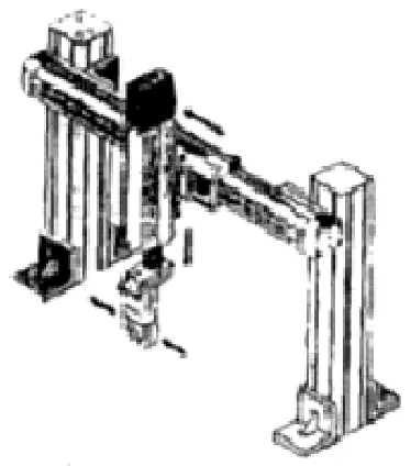
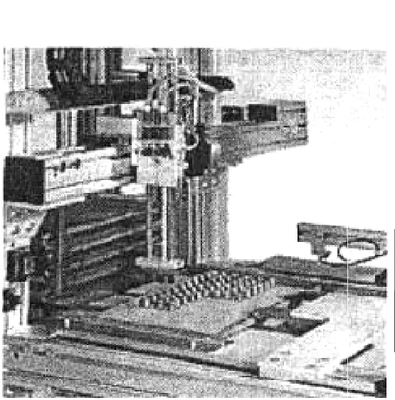
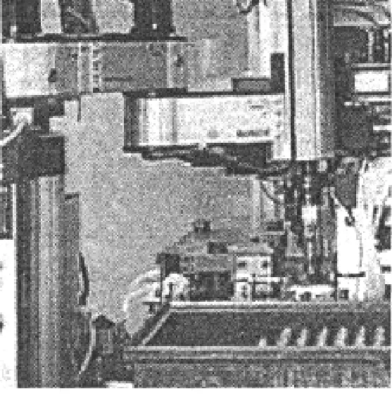
Can be divided into column type, gantry type, coordinate type robotic hands and SCARA type robotic hands, etc., as shown in Figures 8 to 11.
Can be divided into Cartesian coordinate robotic hands, cylindrical coordinate robotic hands, spherical coordinate robotic hands, and articulated robotic hands, etc., as shown in Figure 12.
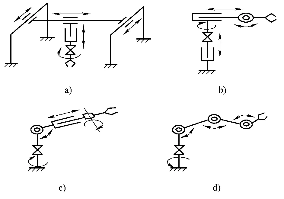
a) Cartesian coordinate robotic hand
b) Cylindrical coordinate robotic hand
c) Spherical coordinate robotic hand
d) Articulated robotic hand
1) Cartesian coordinate robotic hand.
Also known as linear motion robotic hand, as shown in Figure 12a. The arm of the robotic hand can move linearly in the three coordinate axis directions of the Cartesian coordinate system, namely the forward and backward extension, up and down lifting, and left and right movement of the arm.
This type of robotic hand has a simple structure, intuitive movement, high precision, good safety factor, and low cost. The disadvantage is that it requires a larger space for the equipment while having a relatively small working range. It is suitable for situations where work positions are arranged in a straight line and is often used for gripping and conveyor loading and unloading.
2) Cylindrical coordinate robotic hand.
Also known as rotary type robotic hand, as shown in Figure 12b. The arm of the robotic hand can extend forward and backward, lift up and down, and swing in the horizontal plane. It has the advantages of good intuitiveness, high inertia ratio, and simple structure. Compared to Cartesian coordinate robotic hands, it occupies less space while having a larger range of motion.
The characteristic of the cylindrical coordinate robotic hand is that it has a sliding sleeve installed on a vertical guide post, allowing the arm to move linearly in the vertical direction and swing in the horizontal plane. However, due to structural limitations, it cannot grasp objects on the ground.
3) Spherical coordinate robotic hand.
Also known as pitch type robotic hand, as shown in Figure 12c. It has more degrees of freedom and wider applicability. The arm of the robotic hand can extend forward and backward, pitch up and down, and swing left and right.
Compared to cylindrical coordinate robotic hands of the same size, it expands the working range and can grasp objects on the ground. Its motion inertia is smaller, but the longer the arm, the greater the impact of swing angle error on precision. The drawback is that the motion relationships are complex and the cost is higher.
4) Articulated robotic hand.
Also known as jointed type robotic hand, as shown in Figure 12d. Similar to a human arm, the articulated robotic hand consists of an upper arm, forearm, and multiple joints.
It is more flexible than the three types of robotic hands mentioned above, and can even work around obstacles, making it more adaptable to crowded or narrow work environments and more versatile. However, the simultaneous movement of multiple joints leads to poor motion intuitiveness, complex control, complex mechanical structure, low mechanical rigidity, low motion precision, and high cost.
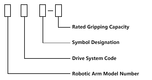
Currently, various units in China generally follow these principles when compiling model numbers for robotic hands:
Labeling model numbers for robotic hands can highlight their characteristics, while other characteristic parameters of the robotic hand can be detailed in the manual. Table 3 shows the compilation codes for robotic hand model numbers.
Table 3 Compilation codes for robotic hand model numbers
| Content represented | Robotic hand | Drive method | Rated gripping mass/kg | Modification order | |||
| Hydraulic | Pneumatic | Electric | Mechanical | ||||
| Code used | JS | Y | Q | D | J | ||
| Digital code | Represented by numbers | Represented by numbers | |||||
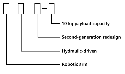
Examples of symbols for robotic hands are shown in Figure 13, and examples of model numbers are shown in Figure 14.
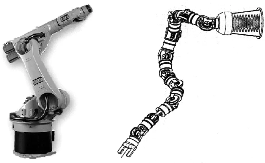
Articulated robots are favored for their flexibility and versatility. Common robots for welding, painting, etc., all belong to articulated robots.
The structure of articulated robots is similar to a human arm, capable of effectively determining the posture of the robot in three-dimensional space. It mainly has two types of movement: rotation and revolving. Through mathematical calculations and trajectory control, it can simulate any curve in space and even easily avoid obstacles to reach any target position in space.
This is particularly important for picking robots. Articulated assembly robots are further divided into two types: planar articulated (i.e., SCARA type) and vertical articulated (i.e., spatial articulated type).
Planar articulated robots are mainly used for assembling irregular chips when making circuit boards. Compared to vertical articulated robots, they occupy less space, have more flexible horizontal movement, lighter load capacity, higher precision, and lower cost. Vertical articulated robots have a larger working area, greater versatility, and more flexible usage. Human
According to the distribution of joints, mechanical hands can be divided into series and parallel types. From the perspective of joint drive methods, they can be further divided into multi-motor driven and single-motor driven mechanical hands, as shown in Figure 15.
Multi-motor drives are relatively easy to control and have simple mechanical structures; while single-motor drives, although more difficult to control, occupy less space and are more flexible to use. Research on articulated robots remains a hot topic in current studies.
During the use of press machines, due to improper equipment selection, errors in the material and thickness of stamped parts, double-feeding errors, and other reasons, the technological force of the slide may exceed the allowable range, causing equipment damage and, in severe cases, even personal accidents.
To ensure equipment and personal safety, presses often employ various overload protection devices. Common overload protection devices are divided into two categories: one is destructive, such as shear plate and crush block protection devices; the other is non-destructive, such as hydraulic, mechanical, and electric instrument overload protection devices.
The crush block is a common destructive safety device used on ordinary presses, as shown in Figure 7-66. When overloaded, the crush block is destroyed, triggering a limit switch, and the press stops. To resume press operation, the crush block must be replaced, and after replacement, the closed height needs to be rechecked, which is quite troublesome and time-consuming.
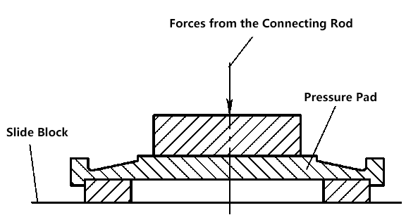
For destructive safety devices, since in most cases one of them breaks first, it can easily cause the slide to tilt, subjecting the guide rails to forces that constrain the slide’s rotation. This can accelerate guide rail wear or even damage components.
Therefore, destructive safety devices are not suitable for double-point and four-point presses. However, due to their simple structure and low manufacturing cost, they are still used on small-tonnage single-point presses.
Hydraulic cushions are used instead of crush blocks as overload protection devices. The hydraulic cushion can obtain accurate protection load through pressure adjustment in the hydraulic system.
When the press experiences an overload, the hydraulic pressure increases, automatically opening the relief valve. The fluid in the hydraulic cushion is quickly discharged back to the hydraulic system. While the slide stops moving, the connecting rod can continue to move downward, and simultaneously, the limit switch sends an overload signal, controlling the clutch to disengage.
After checking and eliminating the cause of overload, the hydraulic system automatically returns to the protection pressure, and the press can continue working. Therefore, the hydraulic overload protection device is non-destructive.
Figure 17 shows the hydraulic principle diagram of a hydraulic overload protection device on a four-point press. There is a hydraulic cushion 4 at the bottom of each connecting rod, and each hydraulic cushion is controlled by a hydraulic relief valve 3. When unloading, the valve core can send an overload signal through the limit switch 2.
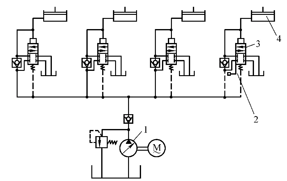
1—Hydraulic pump
2—Limit switch
3—Relief valve
4—Hydraulic cushion
The hydraulic system is supplied by a high-pressure hydraulic pump 1. Generally speaking, the hydraulic overload protection device has accurate protection load, sensitive and reliable action, but the manufacturing cost is relatively high. This system has two drawbacks: first, when the press is unevenly loaded, it is quite difficult to ensure that all relief valves unload simultaneously; second, the high-pressure pump often works in a high-pressure overflow state, making the system prone to heating.
Figure 18 shows a hydraulic system using a pneumatic pump for liquid supply. This system uses a pneumatic pump 1 and pneumatic relief valve 2 to replace the high-pressure pump and relief valve mentioned earlier. The pneumatic pump is an automatic pump that can start automatically when the system pressure decreases and stop automatically when it reaches the set pressure.
1—Pneumatic pump
2—Pneumatic relief valve
3—Hydraulic cushion
4—Pressure regulating valve
During normal operation of the press, the pneumatic pump only serves to supplement pressure, thus having a long lifespan and saving energy. This system has been applied effectively on the J36-800 type press.
Overload protection devices for presses also include mechanical and electric reading instruments. Mechanical reading instruments are more commonly used on small presses produced by Japanese companies. It uses a mechanical strain gauge to measure the deformation of the machine body, which is then amplified through a lever to create a pointer-type instrument. This type of instrument is not suitable for tracking rapidly changing loads in punching processes, but it is very suitable for processes such as deep drawing. Moreover, it is inexpensive and has stable performance.
Electric reading instruments use resistive strain gauges directly attached to the machine body to sense its working deformation. The signal is amplified through circuits and displayed digitally. When it reaches the warning value, it gives an alarm signal and can store the maximum pressure value. It is an automated instrument, relatively expensive, and mainly used on large presses.
Press personal safety protection devices are accessories attached to presses to ensure personal safety. Various protection devices differ in their constraints and have different effects on improving productivity, labor-saving, and safety.
The improvement rate here refers to the length of the maximum allowable auxiliary time when using various protection devices. Labor-saving refers to the reduction in labor intensity due to safety distance limitations when using various protection devices. Safety refers to the extent of control over the press parts and the device itself by various protection devices.
Hand tools include clamps, tweezers, pliers, magnetic suction cups, electromagnetic suction cups, vacuum suction cups, etc. Hand tools should be selected based on the size, shape, and weight of the stamped parts. They mainly replace operators in loading and unloading, avoiding direct contact between the operator’s hands and the upper and lower molds. Hand tool safety protection devices mainly use a two-hand combination method.
The two-hand combination protection device requires the operator to press down two handles simultaneously, or one handle and one button, or two buttons, etc., for the slide to start moving.
This is to restrictively ensure that the operator’s hands are away from the danger zone when the slide is on its downward stroke, thus ensuring safety. The main forms include two-handle interlocking, two-hand buttons, safety buttons, etc.
1) Two-handle interlocking device.
In the device shown in Figure 19, only when both sides of the double handles 1 are pressed simultaneously can the starting rod 2 be pressed to the bottom, allowing the starting device to engage. Pressing either side of handle 1 alone cannot press the starting rod 2 to the bottom, thus preventing the starting device from engaging. This device is generally used on small presses and bench presses.
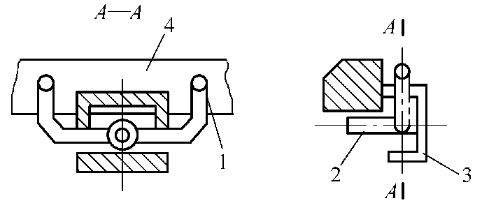
1—Handle
2—Starting rod
3—Cover shell
4—Worktable
2) Two-hand buttons (Two-hand operation safety device).
By simultaneously pressing two buttons or operating handles with both hands, the clutch is approached through electromagnetic force, spring force, air pressure, or manual force, causing the slide to descend.
The operation buttons must be placed beyond the safety distance determined by the press’s emergency stop performance, to forcibly move the operator’s hands away from the danger zone when the slide descends, preventing accidents from occurring if hands are placed between the upper and lower molds after starting and releasing the handles.
This operation must be interlocked with two-hand buttons and is mostly used to control machines operated by a single operator. Two-hand controllers are often installed along with other safety devices and are widely used in various production facilities.
Two-hand buttons can be divided into single-person operation and multi-person operation types. Their advantages are: low investment, small space occupation, easy installation, and convenient starting. The application limitations are: they only provide hand protection, do not provide third-party protection, and have significant potential human-machine control conflicts, such as being ineffective against secondary slide drops caused by mechanical failures.
Two-hand buttons are suitable for presses with friction clutches or movable rigid clutches. If used on rigid clutch presses, the position of the two-hand buttons must also ensure a safe distance.
These refer to devices that use mechanical structures to isolate the danger zone or forcibly move the operator’s arms out of the danger zone when the press slide is on its downward stroke and at the bottom dead center, to ensure safety.
Mechanical protection devices have simple structures and strong reliability. They are particularly effective in ensuring safety when preventing continuous stamping due to failure of the press slide’s starting mechanism or when the slide unexpectedly slides down. This is because mechanical protection devices are linked to the press slide, and their power source comes from the slide. As long as the slide moves downward, it will move the operator’s hands out of the danger zone.
There are various types of mechanical protective devices, which can be broadly classified into protective fence, push-hand, and pull-hand types.
1) Protective fence safety device.
Its principle is to set up a fence between the operator and the danger zone, or around the protected area, which moves with the movement of the press slide. When the slide returns, the fence opens for loading and unloading, and when the slide descends, the safety fence closes, preventing hands from entering between the upper and lower dies.
Safety fences are generally suitable for continuous strokes and can be used on small, medium, and large presses, as well as for single-stroke operations. The design of the fence, especially the gap of the fixed fence, should follow the values listed in Table 4. When the press accidentally starts due to a malfunction and causes the slide to continuously punch, the fence can provide protection as it moves in interlocking with the slide.
Table 4 Fence Gap Table
| Distance between fence and die edge/mm | Fence gap/mm | |
| 0-40 | 6 | |
| >40-60 | 10 | |
| >60-90 | 13 | |
| >90-140 | 16 | |
| >140-160 | 20 | |
| >160-190 | 23 | |
| >190-210 | 30 | |
2) Push-hand safety device.
There are connecting rods, pull rods, and cams connected to the hand push rod on the slide. When the slide descends, it forcibly pushes the hands out of the danger zone. This device must be able to adjust the length and swing of the hand push rod and is equipped with a protective plate to ensure hand safety during slide movement.
It is mainly used for small open presses and can accurately function to provide protection even when the slide falls a second time.
3) Pull-hand safety device.
When the slide descends, through two ropes fitted on the operator’s hands, it pulls the operator’s hands out of the mold into a safe area. As long as the pull strap and pulling force are properly adjusted, safety can be ensured even if the slide falls a second time.
The above-mentioned mechanical protective devices are reliable in action, simple in structure, easy to maintain, and can effectively prevent continuous punching due to mechanical failure. Their disadvantage is that there is a mechanical object moving between the operator and the upper and lower dies, which can easily affect the operator’s line of sight, cause fatigue, and inconvenience feeding and unloading. They are mainly used for safety modifications of old-style presses.
A light beam, air flow, electric field, etc., that does not affect vision and operation is set up between the operator and the upper and lower dies or around the danger zone. When the operator’s body or hand-held object enters the danger zone, it can send a stop signal to the control circuit of the press machinery, causing the slide to stop descending immediately to ensure safety. Automatic protective devices include photoelectric protection, inductive protection, etc.
1) Photoelectric protection device.
It refers to setting up a light curtain between the operator and the upper and lower dies or around the danger zone, forming a detection area with detection capability. When the operator’s body or hand-held object enters the detection area and blocks the light curtain, the control mechanism sends a shutdown signal, ordering the slide to stop descending immediately, achieving the purpose of protection.
This device is mainly used for double-action deep drawing processing, continuous processing, and foot switch operation, but it is ineffective in preventing the slide from falling a second time due to press failure.
Its advantages are: high reliability and strong resistance to electrical interference. Usage limitations include: occupying space, and often requiring the addition of fixed protective devices.
Photoelectric protection can be classified into visible light and infrared light types according to the light source; and into direct, reflective, and scanning types according to the form of the light curtain.
① Visible light photoelectric protection:
Visible light type generally uses incandescent lamps as the light source. The filament is prone to breaking when vibrating, resulting in a shorter lifespan. However, its electrical circuit is simple, cost is lower, and maintenance is easy, generally suitable for small and medium-sized presses. Visible light photoelectric protection is difficult to implement for complete self-checking.
② Infrared photoelectric protection:
Infrared photoelectric protection generally uses infrared light-emitting diodes as the light source, which have a long lifespan, strong vibration resistance, and are semi-permanent. It uses modulated light, making self-checking easy; however, the electrical circuit of infrared photoelectric protection is more complex and costs are higher. It is generally used for large and medium-sized presses. Currently, more advanced infrared photoelectric protection devices are equipped with safety light curtains, laser scanners, etc.
③ Safety light curtain:
Composed of a transmitter and a receiver, the transmitter emits modulated infrared light, which is received by the receiver, forming one or more light grids to separate the operator from the danger zone.
When a part of the operator’s body enters the danger zone, the light is blocked and an electrical signal is sent. This signal is amplified and interlocked with the slide control circuit to stop the slide’s movement.
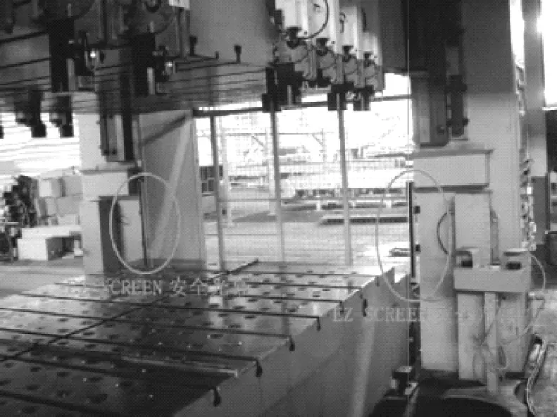
Figure 20 shows a press equipped with a pair of safety light curtains. Photoelectric safety devices generally use modulated infrared light-emitting diodes as the light source, while infrared laser diodes are used on large presses. Their circuits have complex and reliable self-checking and self-protection functions.
Safety light curtains are generally divided into two types: through-beam and reflective. The through-beam safety light curtain refers to a safety light grid device where the light-emitting unit and light-receiving unit are separately located in the emitter and receiver, with light from the light-emitting unit directly reaching the light-receiving unit to form a protective light curtain.
The reflective safety light curtain refers to a safety light grid device where both the light-emitting unit and light-receiving unit are in the same sensor, with light from the light-emitting unit reflected back to the light-receiving unit through a reflector to form a protective light curtain.
④ Laser scanner:
Laser scanners are used to protect areas around dangerous machinery. As soon as an object larger than 70mm in diameter (such as a foot or leg) is detected, the equipment triggers a stop signal for the machine’s safety control system.
In addition, this type of equipment has an early warning function, allowing people to be warned before entering the danger zone, thereby avoiding unnecessary shutdowns. It’s easy to program for complex-shaped protection areas and can expand the protection area, but it’s sensitive to environmental pollution levels.
2) Inductive protection device.
Inductive protection devices use electromagnetic curtains to surround the danger zone to protect personal safety, including capacitive and human body sensing types.
Human body sensing protection is related to the human body, and since each person’s conditions are different, its adaptability is poor and requires frequent adjustment, reducing reliability. Moreover, due to the abundance of external electromagnetic waves, its anti-interference ability is not ideal, and it has rarely been used domestically and internationally.
However, the components of the electromagnetic curtain are relatively easy to install and remove, which is beneficial for changing molds. If the reliability of inductive protection devices is not much different from photoelectric ones, then their application prospects in small and medium-sized presses are still quite significant.
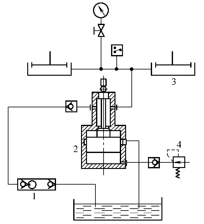
Figure 21 shows a capacitive protection device used on a press. Its sensing element is placed between the operator and the mold, and loading and unloading must pass through the cavity of the sensing element. When a hand passes through the cavity, the press slide stops moving or cannot start, ensuring the operator’s safety.
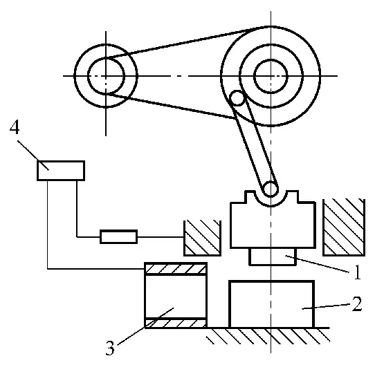
1—Punch
2—Die
3—Sensing element
4—Controller
The human body sensing protection device sets up a capacitor with a certain capacitance to ground as a sensing element between the operator and the danger zone. By changing the distance between the human body and the sensing element during loading and unloading, it changes the size of the capacitor to ground, which, after amplification, can stop the machine or prevent it from starting.
Since inductive protection is greatly affected by various factors of the human body and the site (for example, different shoes and socks worn, the age of gloves worn, etc.), it is extremely inconvenient to use.
3) Air curtain protection device.
An air curtain is set up between the operator and the danger zone. Once the operator’s hand, body, or other object blocks the air curtain, it disconnects the control circuit of the starting device, stopping the slide’s movement or preventing it from starting.
The above-mentioned automatic protection devices do not have mental or visual impacts on operators, thus reducing mental fatigue; however, they are ineffective against slide secondary falls caused by malfunctions.