I. Overview
1. Automatic Control
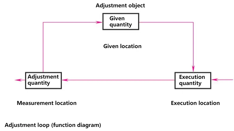
Automatic control is the process of using additional devices or equipment (control devices) to make machines, equipment, or production processes (controlled objects) automatically operate according to predetermined rules in terms of certain working states or parameters (controlled variables) without direct human intervention.
For example, CNC lathes automatically cutting according to predetermined programs, or artificial satellites accurately entering predetermined orbits and being recovered. Automation is essentially the automatic regulation and control of machines or equipment.
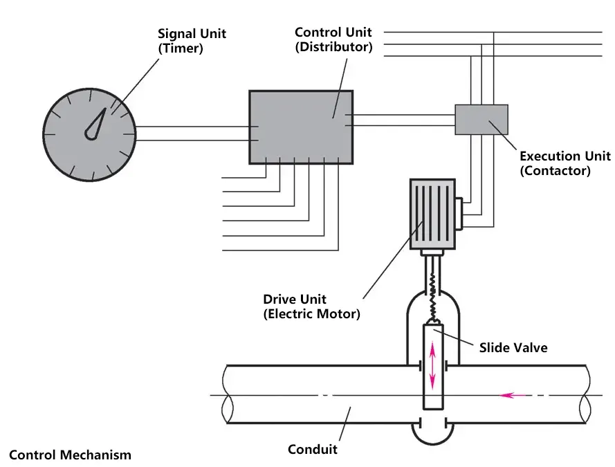
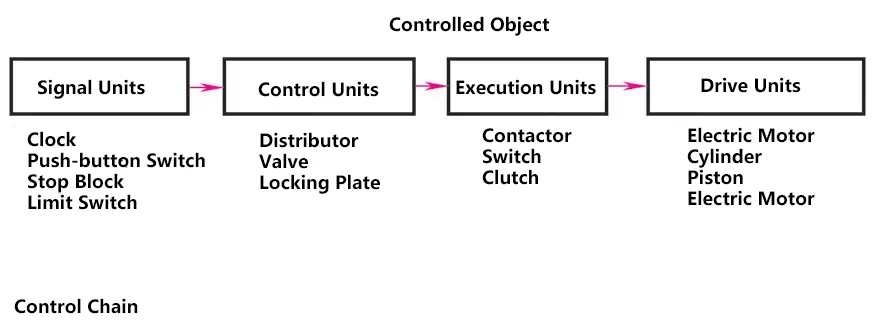
An automatic control system refers to a system that can automatically control the working state of a controlled object. It is a combination of the controlled object and the devices or components involved in realizing the automatic control of its controlled variables, generally consisting of control devices and controlled objects.
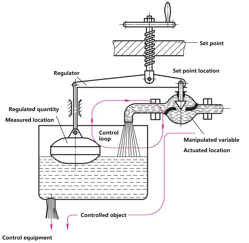
In the side figure, the float transmits the water level height to the valve, and the valve opens or closes according to the water level height. The desired water level can be adjusted by changing the set value.
Through the continuous feedback process of the actual state (water level height), it is constantly adjusted according to the actual state until the desired state (set state = desired water level height) is reached.
With the help of control and regulation devices, it is now possible to automate the machining process of workpieces (such as engine cylinder blocks) that require hundreds of operations on multiple sequentially arranged machine tools. Many operations are controlled, and some main operations are regulated. However, even a simple copying operation on a lathe can be considered a controlled work process.
2. Control Methods
(1) Open-loop Control
The controlled variable (output) of the system is only controlled by the control action, and the control method cannot produce any influence. Systems using open-loop control are called open-loop control systems.
Advantages: Simple structure, low cost, easy to implement.
Disadvantages: No ability to suppress disturbances, low control accuracy.
(2) Closed-loop Control
A control method where there is negative feedback between the system’s controlled variable (output) and the control action. Systems using closed-loop control are called closed-loop control systems or feedback control systems. Closed-loop control is the basic rule for all biological control of their own movements. Humans themselves are highly complex closed-loop control systems with advanced control capabilities.
Advantages: Ability to automatically compensate for system errors (deviations) caused by internal and external disturbances, thereby effectively improving system accuracy.
Disadvantages: System parameters must be appropriately selected, otherwise, it may not work properly.
(3) Composite Control
A control method that combines open-loop and closed-loop control. It is based on a closed-loop control loop with an additional feedforward path for input signals or disturbance signals to improve system control accuracy. The feedforward path usually consists of compensators for input signal compensation and disturbance signal compensation.
Advantages: High control accuracy, can suppress almost all measurable disturbances.
Disadvantages: Compensator parameters require high stability.
3. Concept of Block Diagrams

- Blocks – Control devices and controlled objects are represented by blocks.
- Signal lines – The inputs and outputs of blocks and their connections are represented by arrowed signal lines.
- Input signal – The signal entering a block.
- Output signal – The signal leaving a block.
Open-loop control system block diagram:

Closed-loop control system block diagram:

4. Classification of Automatic Control Systems
There are multiple classification methods for automatic control systems, as shown in the table below.
Classification of Automatic Control Systems
| Classification Method | Types |
| By signal flow direction | Open-loop control, Composite control |
| By system function | Temperature control, Pressure control, Position control, Level control, etc. |
| By component type | Mechanical, Electric, Pneumatic, Hydraulic, Biological, etc. |
| By system performance | Linear and nonlinear, Continuous and discrete, Time-invariant and time-varying, Deterministic and uncertain, etc. |
| By system input signal | Constant value regulation, Servomechanism, Program control |
II. Servo Control Systems
A servo system is an automatic control system that enables the output controlled variables such as position, orientation, and state of an object to follow arbitrary changes in the input target (or set value).
Its main task is to amplify, transform, and regulate power according to control commands, making the control of torque, speed, and position of the drive device very flexible and convenient. Several common types of servo control are as follows.
A typical application of servo controls are copy turning. There are lathes specially designed for this process. The tool contacts the workpiece from above or behind to ensure unobstructed chip removal.
1. Mechanical Servo Control
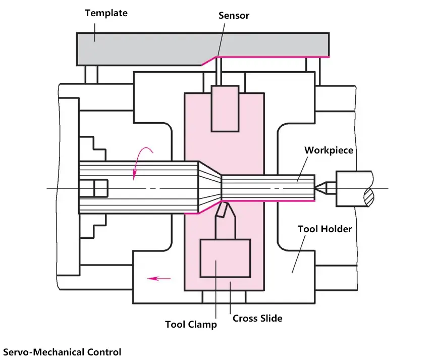
As the carriage continuously feeds, a sensor (signal unit) moves along a template or standard sample. Through a rigid connection between the sensor and the tool, the tool is forced to move along the same trajectory, and the workpiece is machined according to the template. The sensor must be pressed against the template by the 反向力 of the tool.
2. Electric Servo Control
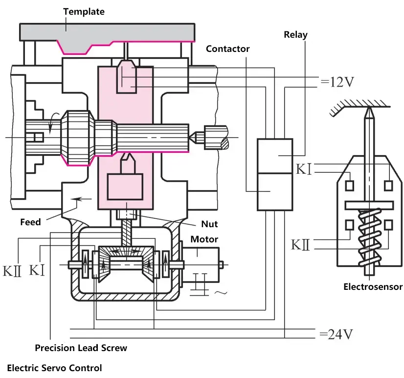
Here, the longitudinal carriage also feeds continuously. If the sensor does not contact the template, the contact KI in the sensor box closes automatically.
The clutch KI operates through a relay (control unit) and contactor (actuator), so the motor drives the tool slide towards the workpiece until the sensor contacts the template. At this point, contact KII closes, and the motor drives the tool slide back until the sensor leaves the template.
3. Hydraulic Servo Control
This copying device can be attached to a lathe. Its advantage is higher copying accuracy.
4. Electro-hydraulic Servo Control
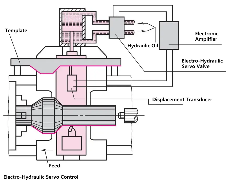
In this device, the contour of the template is sensed by a stylus or sensor, and the pulse signal is amplified in an electronic tube.
By receiving this signal, the electromagnet activates the hydraulic control valve in less than 1 second, initiating a control process that immediately directs a powerful oil flow to the hydraulic piston. After a short conversion time, very high copying accuracy is achieved.
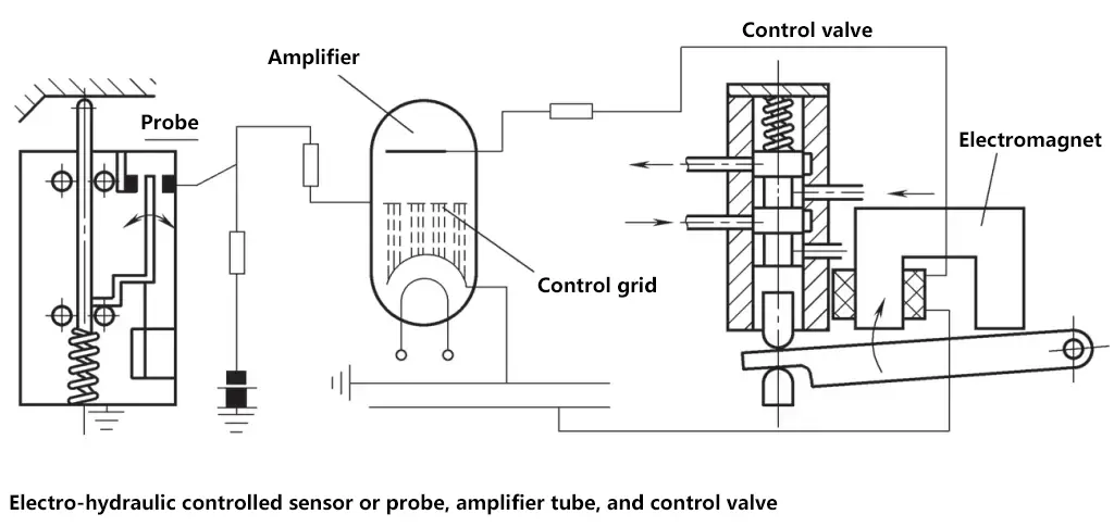
If the stylus doesn’t contact the template, the flip-flop lever connects the contact to the right, reducing the grid voltage of the amplifying tube to zero (grounded). This allows the current in the tube to flow freely, exciting the electromagnet’s coil and attracting the armature, opening the valve’s oil passage.
Pressure oil enters the piston, and the cross slide moves the tool towards the workpiece until the stylus touches the template. Then the contact opens, cutting off the grid voltage and current. If the control valve closes both the output and return passages, the piston becomes fixed between the upper and lower oil chambers.
III. Program Control Systems
In program control systems, the set value changes according to a specific time function. For example, the output of a program-controlled machine tool’s program control system should follow the same pattern of change as the set value.
The set value in a program control system is variable, but it is a known function of time, meaning the set value changes according to a time program specified by the operator.
This type of system is widely used in intermittent production processes, such as automatic mixing and heating control of multiple liquids.
Components of a program control system: switch signals, input circuits, program controller, output circuits, and actuators, etc.
1. Electric Program Control
Milling machines often use electric control devices. The control program is divided into two storage systems. The movement length is determined and stored by adjusting the stops on the stop plate, which is set along the direction of the worktable movement. Thus, the stops on the plate limit the movement length – when to generate switching pulse signals.
Then, this pulse enters a pin board or punched tape device. From here, control pulses continue to output to the corresponding drive elements, such as feed motors or milling cutter drive devices. This determines where the pulse takes effect.
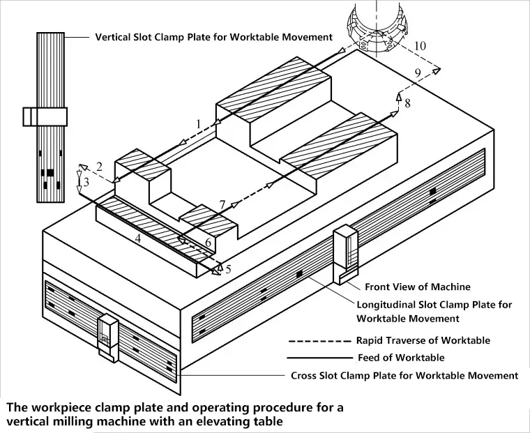
Longitudinal Travel of the Worktable:
- 1 – E1 = Limit Switch
- 2 – E2 = Limit Switch
- 3 – E3 = Limit Switch
- 4 – E4 = Limit Switch
- 5 – Feed, Right
- 6 – Rapid Traverse, Right
- 7 – Feed, Left
- 8 – Rapid Traverse, Left
Cross Travel of the Worktable:
- 5 – Feed, In
- 6 – Rapid Traverse, In
- 7 – Feed, Out
- 8 – Rapid Traverse, Out
Vertical Travel of the Worktable:
- 5 – Feed, Down
- 6 – Rapid Traverse, Down
- 7 – Feed, Up
- 8 – Rapid Traverse, Up
2. Mechanical Program Control
Fully automatic or semi-automatic lathes often use cam drums or cam discs for control. The single or multiple tool turrets or hexagonal heads are equipped with necessary turning tools, as well as reamers, drills, boring tools, center drills, or thread cutting heads.
The uniformly rotating cam drum or cam disc controls (mostly through travel control) the preparation of tools and the rotation of the tool holder, followed by moving the slide and tool holder towards the workpiece at the correct feed rate.
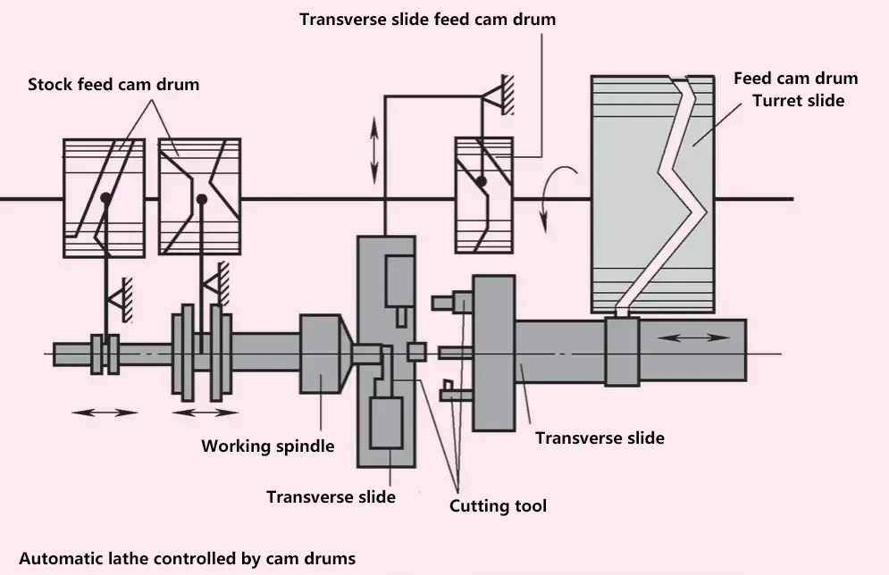
For fully automatic lathes commonly used for bar stock machining, material feeding, clamping, and cutting off are also completed through the program. The drawback of these machines is the long setup time; installing all cams and adjusting all tools may take several days, during which the machine cannot produce.
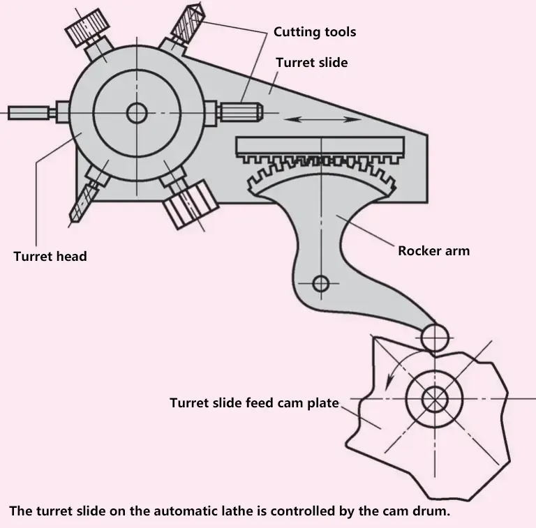
Due to tool wear, workpiece dimensions need to be frequently monitored and checked. These machines are only economical for large-batch production of parts.
3. Pneumatic-hydraulic Program Control
Hydraulic, pneumatic, or a combination of both controls are often used for feed movements due to their smooth operation, noiselessness, and infinitely variable speed control, such as in grinding machines. According to their pulse transmission method, they can be time sequence, travel, and operation control.
In the figure below, the main piston is driven by compressed air through the compressed air channel. A hydraulic cylinder with a piston is connected in series with the air cylinder for speed control of the rapid traverse E and feed stroke V.
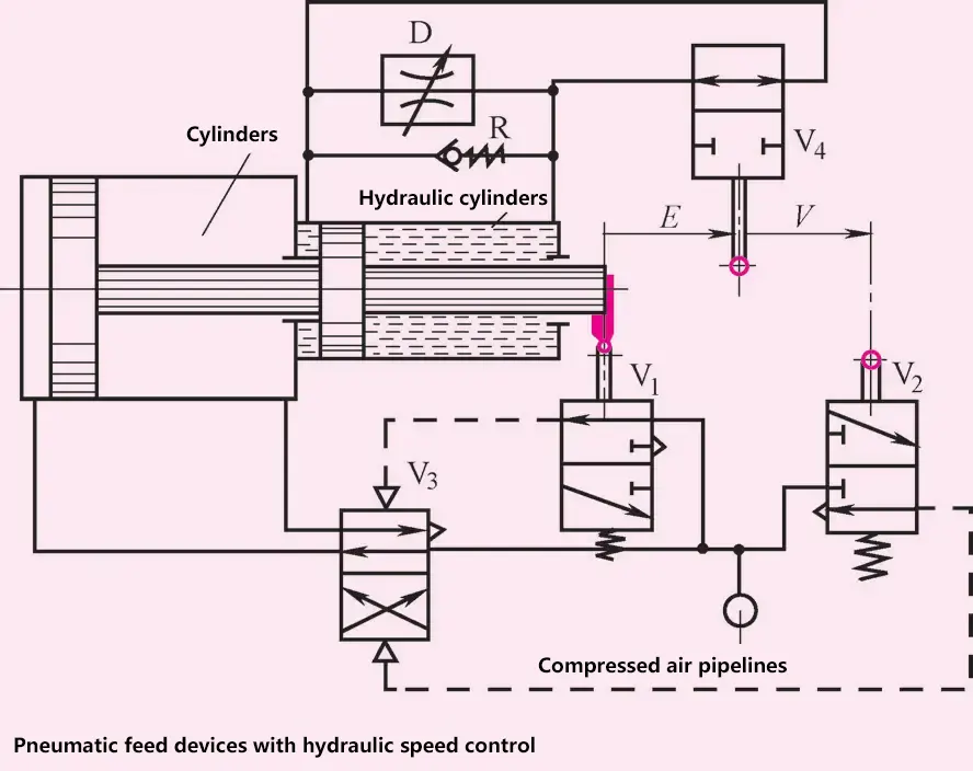
During rapid traverse, hydraulic oil flows unhindered from the right oil chamber to the left oil chamber through valve V0, the volume of the right chamber decreases due to piston movement, while the left chamber volume expands. When the rapid traverse ends, valve V1 switches, and the small flow of the throttle valve D reduces the piston movement speed.
The V 1 and V 2 two valves at the piston stroke terminal control V 3, compressed air through valve V 3 to control the forward and backward movement of the main piston.
IV. Digital Control
Digital control is an automated method of programming control over a work process using digits, characters, or other symbols.
It typically uses a dedicated computer, with operation instructions represented in digital form, and the machine equipment works according to a predetermined program, abbreviated as NC (Numerical Control). It usually controls position, angle, speed, and other mechanical quantities as well as switching quantities related to the flow of mechanical energy.
The emergence of numerical control relies on the appearance of data carriers and binary data operations. Numerical control technology developed closely integrated with machine tool control and is also known as computer numerical control technology. Currently, it adopts computers to implement digital program control.
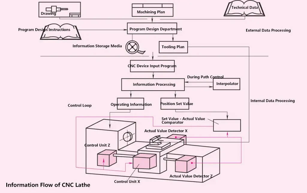
This control principle can be clearly understood from the information flow shown in the following diagram. According to the information source, such as technical drawings, processing plans, and technical data, with the help of program design instructions, the program design department can prepare information storage media (NC devices) and tool plans.
The tool preparation department prepares the necessary tools for processing according to the tool plan. The tools can be changed manually or automatically from the tool magazine.
The tools should be accurately installed on the tool holder and do not need to be adjusted or calibrated again. The NC device and tool magazine can be conveniently equipped on the machine tool. Within a few minutes, the program can be input, the tools mounted, and the workpiece clamped. In this way, the machine tool is ready to work.
Since this type of machine tool has the advantage of short changeover time for different jobs, it is particularly suitable for small to medium batch production of workpieces. The preparatory work is done outside the machine, i.e., in the program design department and the tool adjustment department. This preparatory work is called external data processing.
When the program is input, the NC device receives the information, stores it, and further processes the information as needed. The information is converted into operation information for spindle speed and feed rate, as well as position setpoint values (stroke setpoints) for the slide movements in the Z=longitudinal direction and X=transverse direction. The operation information is fed to the actuators controlling the main drive and feed drive.
The position setpoint values are input into the adjustment mechanisms for the longitudinal and transverse slides via a setpoint-actual value comparator. The actual value detectors continuously feed back the instantaneous actual dimensions to the setpoint-actual value comparator, which continuously actuates the adjustment mechanisms until the fed-back actual dimension matches the predetermined setpoint value from the program. This is a control process.
For example, to turn a spherical shape, the necessary information such as the maximum stroke in the X direction, the maximum stroke in the Z direction, and the sphere radius must be sent from the information processing unit to the interpolator (computer).
According to the pre-stored program, the interpolator calculates the simultaneous, time-varying motions of the slides in the X and Z directions and sends them back to the information processing unit.
1. Information Source
The data on the shape and dimensions of the workpiece to be machined (technical drawings), data on the processing procedure (processing plan), processing specifications such as cutting speed, feed rate, and other similar technical data, as well as program design instructions required for each machine tool and each numerical control system, are the information sources used by the programmers.
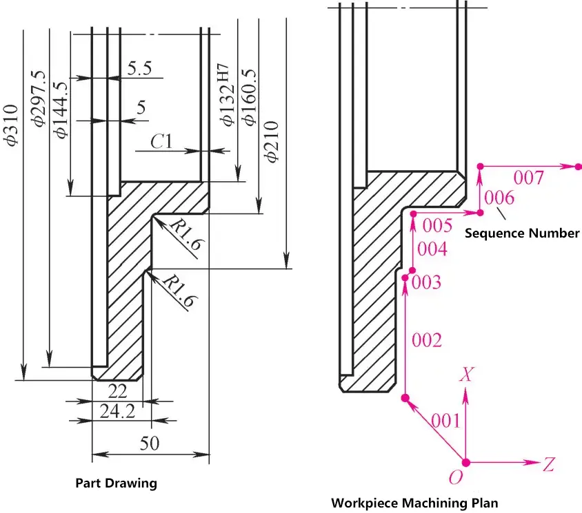
The programmers must theoretically rehearse (simulate) the entire processing procedure, and for every action, even the smallest and seemingly irrelevant action of the machine tool, they must provide a corresponding instruction (information) on the information carrier or storage medium. In this way, the technician no longer needs to decide what speed to set, whether to apply coolant lubrication, or when to apply it.
These decisions have already been made in the program design department before the workpiece starts processing. Based on the drawings, traditional processing plans, and technical parameters, a processing plan is compiled, which divides the processing procedure into individual steps (statements).
Each step is determined by the statement number, the direction of movement of the X and Y axes, the distance of movement, the feed rate, the spindle speed, and the auxiliary functions (such as coolant lubrication).
2. Actual Value Detection (Stroke Detection)
Numerical control involves controlling the achievement of position setpoints. The actual position value must be continuously compared with the position setpoint. For this purpose, a device is needed that can accurately read the actual value and send it to the setpoint-actual value comparator.
(1) Comparison Measurement (Analog Measurement)
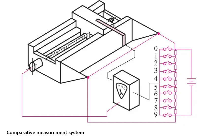
A sliding contact fixed on the slide picks up a voltage corresponding to the slide stroke from a slide-wire resistor. This voltage (actual value) is compared with a voltage (setpoint value) generated by a circuit-determined resistor. In the figure on the right, the voltage with switch 4 closed is taken as the setpoint value.
In practical measurement, three such bridge circuits are used: one for coarse adjustment, one for semi-fine adjustment, and the third for fine adjustment.
(2) Incremental Measurement (Incremental Stroke Measurement)
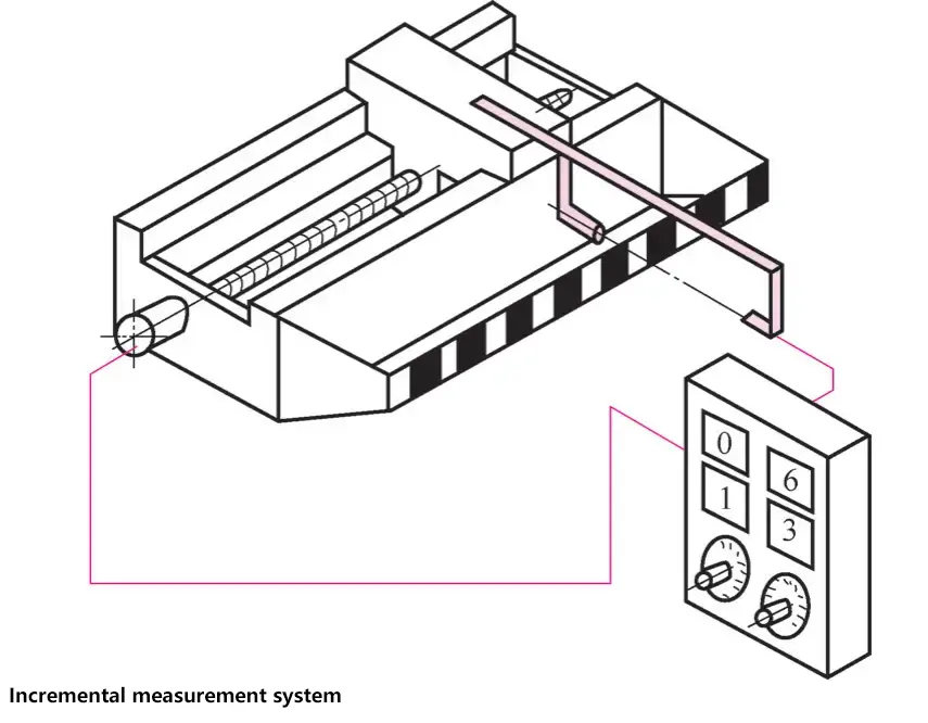
A glass scale has alternating light and dark areas at certain intervals, e.g., every 0.01 mm. A photo-electric cell mounted on the slide scans the scale, and each time a light-dark transition is detected, a pulse is sent to a counter. The count on the counter corresponds to the actual stroke value.
(3) Absolute Value Measurement (Absolute Stroke Measurement)
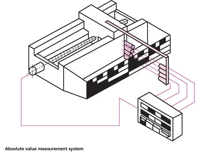
Multiple photo-electric cells sense a scale with multiple light and dark lines. Each length corresponds to a combination of light and dark fields, which is displayed as a dimension, i.e., the actual value, on an indicator.
3. Types of Numerical Control
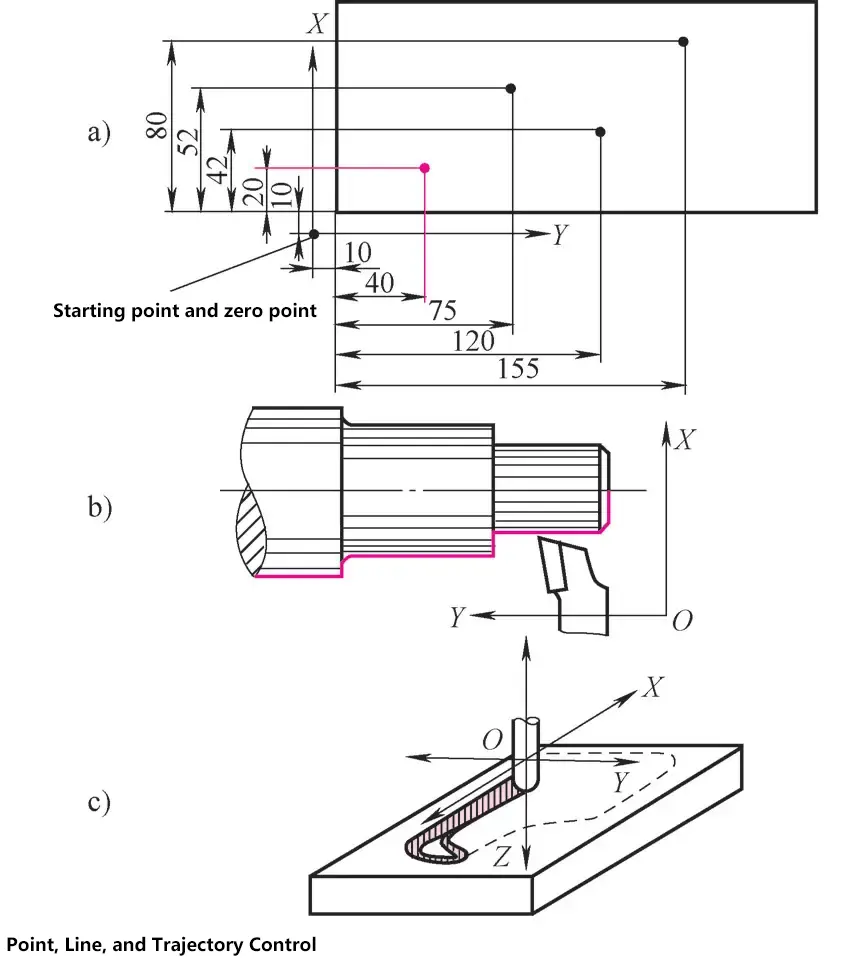
(1) Point-to-Point Control
In point-to-point control, only the end points of the stroke are controlled, so it was initially used on drilling machines. For example, if two strokes of X=50 and Y=30 are required, they can be executed sequentially or simultaneously; the order does not matter. This process can only start after reaching the programmed coordinate points for cutting.
(2) Straight Line Control
In straight-line control, the movement is always in one direction, either the X direction or the Y direction. Only in a few exceptional cases is there simultaneous movement in two directions, using equal-speed motions in both directions to create 45° chamfers or internal corners.
The desired workpiece shape is produced through a specific sequence of strokes in the X and Y axes and their respective lengths. The workpiece is machined through straight-line motions.
(3) Contouring Control
In contouring control, complex workpiece shapes can be machined by simultaneous motion in two or even three directions. The required velocities in the simultaneously moving directions must be calculated by an interpolator (computer). Contouring control machines can also be used for point-to-point and straight-line control operations.
Numerical control technology has widespread applications in industries such as mechanical manufacturing, printing, textiles, packaging, and building materials.

