I. Scope of Work for Fitters
A fitter is a worker who manually operates tools, instruments, or equipment to manufacture parts, install, debug, and repair equipment. According to the different work characteristics and contents of fitters, they are usually divided into mold fitters, maintenance fitters, and assembly fitters.
II. Organization and Conditions of Fitter’s Work
1. Organization of Fitter’s Work
(1) Preparation before processing
- Arrange the blanks, tools, and measuring instruments in an orderly manner.
- Prepare a footboard according to height and bench vise height.
- Clip the drawing and hang it in the designated position.
(2) Precautions during processing
- Measuring instruments should not be mixed with tools, and precision measuring instruments should be handled gently and placed in a box after use.
- Regularly clean iron filings to keep the work surface clean.
- The processed parts should be neatly stacked in a fixed location.
(3) Cleanup work after processing
- Wipe the measuring instruments clean with a cleaning cloth.
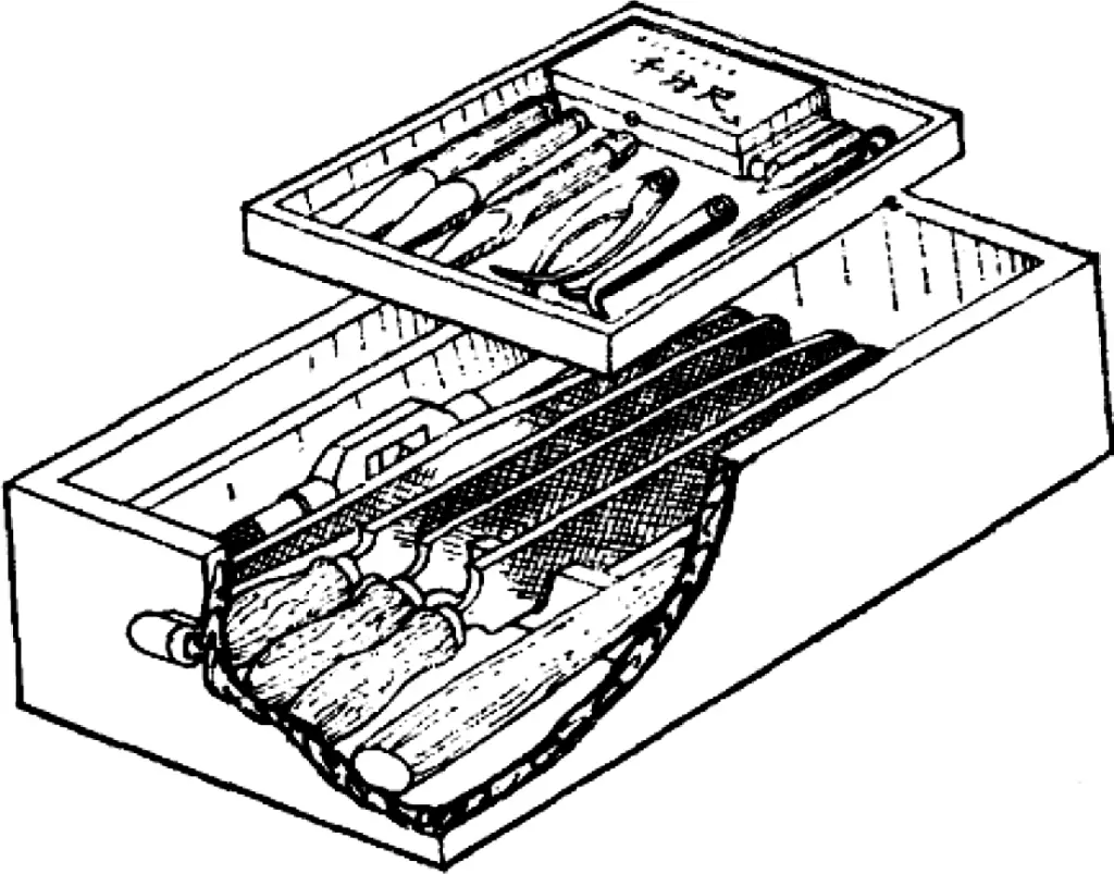
- Neatly arrange the workpieces and tools in the tool cabinet, as shown in Figure 1.
- Clean and wipe the bench vise, keeping a certain gap (5-10mm) between the two jaws, with the handle vertically downward.
- The work area should be swept clean, and iron filings and garbage should be disposed of in designated locations.
2. Working Conditions for Fitters
- The work area should be spacious, and the placement of workbenches should consider lighting and light source arrangement.
- Grinding machines and drilling equipment should be installed in dedicated rooms or at the edge of the work area.
- The shape of fitter’s tool handles should be reasonable, such as file handles, hammer handles, etc.
III. Common Equipment for Fitters
1. Workbench (Vise Bench)
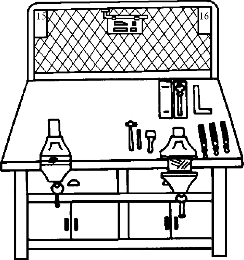
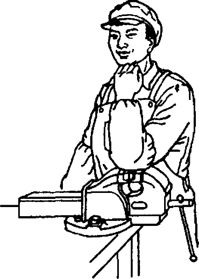
Figure 2 shows a common workbench for fitters. It is a specialized bench for fitter operations, generally made of hardwood or steel-wood structure, available in single-person and multi-person versions. The tabletop is 700-900mm from the ground, with a thickness of 60-80mm. The bench vise is installed on the tabletop, with its jaw height at elbow level, as shown in Figure 3.
2. Bench Vise
(1) Specifications of bench vise
A bench vise is a fixture installed on the workbench for holding workpieces, available in fixed and swivel types, as shown in Figure 4. The specification of a bench vise is expressed by its jaw width, with common sizes being 100mm, 125mm, 150mm, etc.
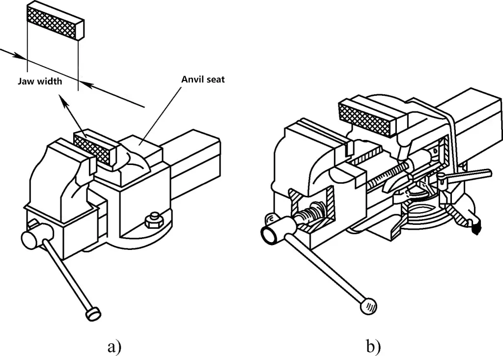
a) Fixed bench vise
b) Swivel bench vise
(2) Structure of bench vise
The main body of the bench vise is made of cast iron and bolted to the bench, with its structure shown in Figure 5. Its opening and closing are achieved through the screw transmission between the lead screw and nut. The swivel bench vise has a locking handle on the turntable base, with external threads at the front end that match the rotating plate at the bottom of the bench vise. When needed, loosen the locking handle, and the vise body can rotate. When rotated to the desired position, the locking handle can be tightened.
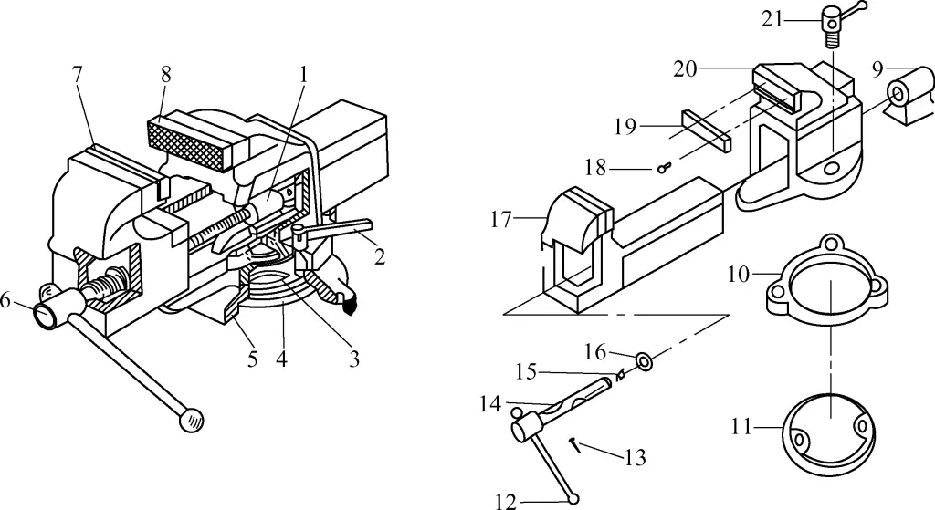
1, 9—Nut
2, 21—Rotating plate locking handle
3, 10—Rotating plate
4, 11—Base
5—Turntable base
6, 14—Lead screw
7—Movable jaw
8—Fixed jaw
12—Handle
13—Pin
15—Buffer spring
16—Washer
17—Movable jaw body
18—Jaw fixing screw
19—Jaw (hardened)
20—Fixed jaw body
(3) Precautions for using bench vise
1) When installing the bench vise on the workbench, the working surface of the fixed jaw must be beyond the edge of the workbench to ensure that the lower end of bar-shaped workpieces is not obstructed by the workbench edge when clamped, as shown in Figure 6.
2) The bench vise must be firmly fixed to the workbench, with both fixing bolts tightened to prevent the vise body from loosening during work. Otherwise, it may damage the bench vise and affect work quality.
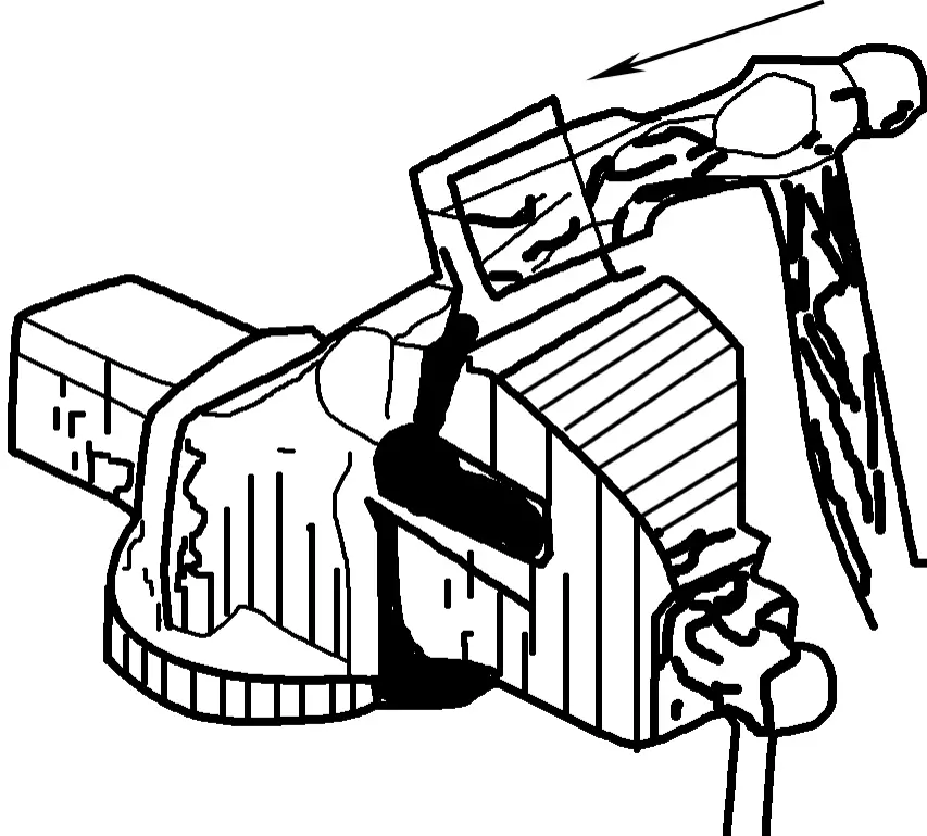
3) When clamping workpieces, only manual force is allowed to turn the handle. Never hit the handle with a hammer or arbitrarily use a long pipe to turn the handle, to avoid damaging the lead screw, nut, or vise body, as shown in Figure 7.
4) During high-force operations, the force direction should be towards the fixed jaw body. Otherwise, it will increase the load on the lead screw and nut, causing thread damage. In severe cases, it may break the nut, rendering the bench vise unusable, as shown in Figure 8.
5) Tools can be placed on the anvil seat of the bench vise, which can also be used for straightening small thin plates. However, do not perform hammering operations on other smooth surfaces of the movable jaw body, as this will reduce its fitting performance with the fixed jaw body.
6) Regularly clean dirt from the lead screw, nut, and other moving surfaces, add lubricating oil, and keep them clean. This prevents rust, improves transmission flexibility, and extends the service life of the bench vise.
7) When possible, try to clamp workpieces in the center of the bench vise to avoid uneven force on the jaws, as shown in Figure 9.
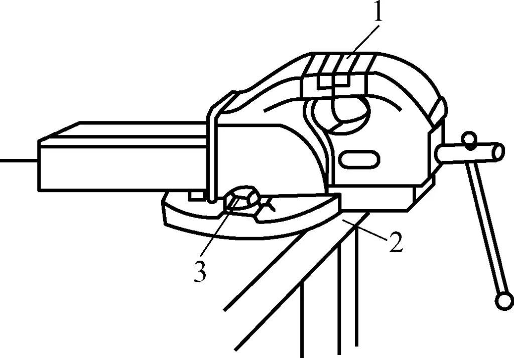
1—Jaw
2—Workbench
3—Fixing bolt

a) Correct usage method
b) Incorrect usage method
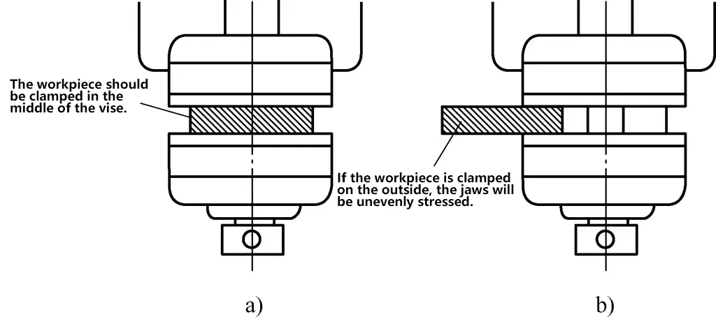
a) Correct clamping method
b) Incorrect clamping method
3. Grinding Machine
(1) Types and uses of grinding machines
Grinding machines are mainly used for sharpening cutting tools and other tools, such as drill bits, chisels, scribers, and punches. They can generally be divided into two types: standard grinding machines and dust-collecting grinding machines, as shown in Figure 10.
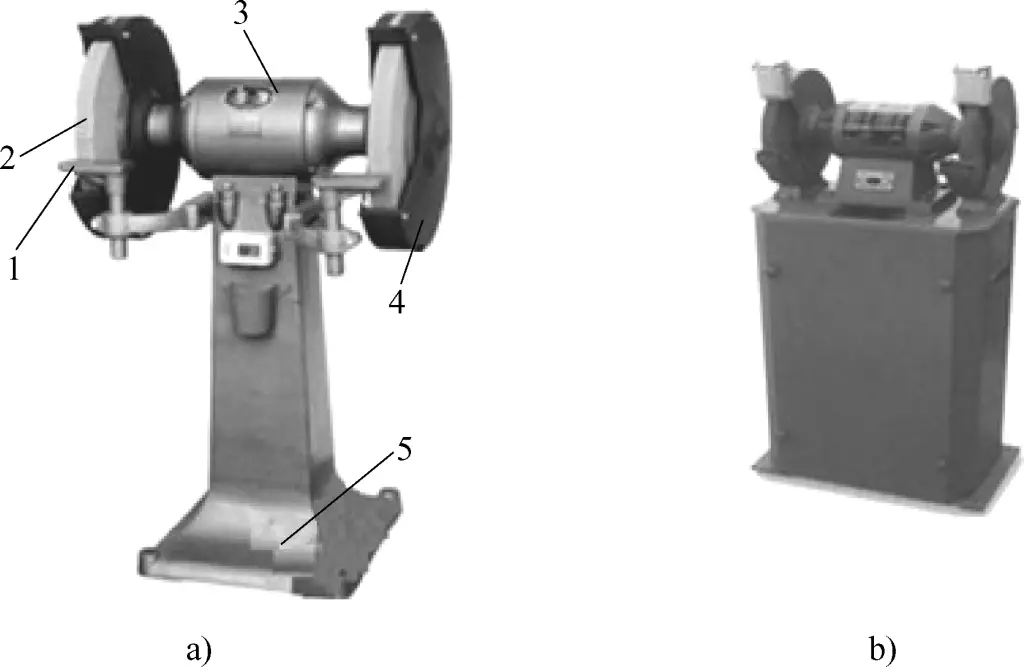
a) Standard grinding machine
b) Dust-collecting grinding machine
1—Tool rest
2—Grinding wheel
3—Electric motor
4—Guard
5—Base
(2) How to use a grinding machine
1) Preparation before operating the grinding machine
- Check the gap between the tool rest and the grinding wheel, which should not exceed 3mm; adjust the height of the tool rest so that the grinding area of the workpiece is on the same plane as the center of the grinding wheel.
- Check if the power cord is damaged.
- Check if all parts of the grinding machine are in good condition, if bolts and nuts are securely fastened, and especially if the grinding wheel has any cracks or defects.
- Wear protective goggles.
2) Precautions for operating the grinding machine
- Start the grinding machine and observe its operation. Use “listening, looking, and smelling” methods to check the running condition of the grinding machine: After the grinding wheel starts rotating, listen for any abnormal sounds, such as impact or screeching noises. If any unusual sounds are heard, stop the machine immediately; After the grinding wheel starts rotating, observe if the rotation direction is correct, check for vibrations in various machine parts and any wobbling of the grinding wheel. If any abnormalities are found, stop the machine immediately; After the grinding wheel starts rotating, check for any unusual smells, such as burning odors. If any abnormalities are detected, stop the machine immediately.
- When the grinding machine is just started, do not rush to use it. Wait until the grinding wheel reaches its normal speed before starting grinding operations.
- During operation, be careful not to touch the grinding wheel to avoid injuring your hands.
- No one should stand in front of the grinding wheel. The operator should stand to the side of the grinding wheel.
- Do not allow two people to use the same grinding wheel simultaneously; do not grind on the side of the grinding wheel; do not use the grinding machine to grind soft metals, non-metals, or large workpieces.
- Maintain a gap of 20-30mm between the side of the grinding wheel and the inner wall of the guard.
- When grinding, do not apply excessive force. Hold the tool firmly to prevent it from jumping on the grinding wheel.
- If any abnormalities occur during the operation of the grinding machine, stop the machine immediately or cut off the power supply.
- After use, switch the grinding machine to the stop position, then unplug the power cord.
- Wipe off the dust on the grinding machine to keep it clean.
3) Maintenance and care of grinding machines
- Keep the machine table clean.
- Regularly ensure that the dust exhaust holes are clear.
- When installing the grinding wheel, place soft pads between the wheel and the side plates. Never strike the nut forcefully.
- Replace the grinding wheel when its effective radius has worn down to 1/3 of its original radius.
4. Drilling Machine
Drilling machines include bench drills, upright drills, and radial drilling machines, which are hole-processing equipment.
As shown in Figure 11a, a bench drilling machine, also known as a bench drill, is a small drilling machine used on tabletops. It typically drills holes with diameters of 13mm or less, with the smallest possible hole diameter being 0.1mm. Bench drills are compact, flexible, and easy to use. They are the main equipment for drilling small diameter holes and are most commonly used in instrument manufacturing, fitter work, and assembly.
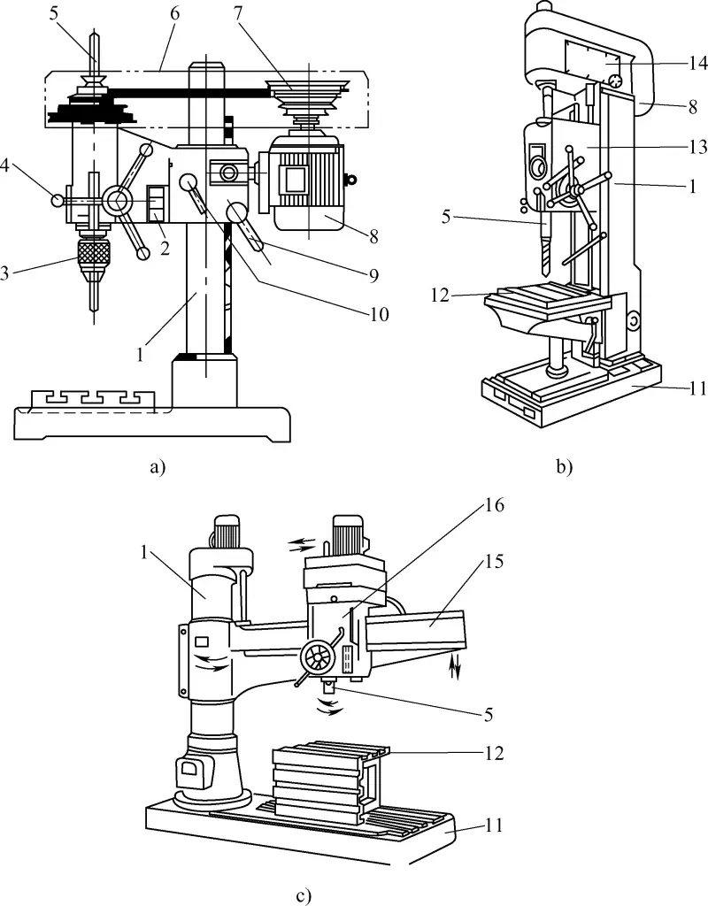
a) Bench drilling machine
b) Upright drilling machine
c) Radial arm drilling machine
1—Column
2—Switch
3—Drill chuck
4—Feed handle
5—Spindle
6—Drive belt cover
7—Tower V-belt pulley
8—Motor
9—Elevating handle
10—Locking handle
11—Base
12—Worktable
13—Feed box
14—Spindle speed gearbox
15—Radial arm
16—Spindle head
As shown in Figure 11b, the vertical drilling machine, also known as a vertical drill, is a medium-sized drilling machine. This type of drilling machine has maximum drilling diameters of ϕ25mm, ϕ35mm, ϕ40mm, and ϕ50mm, among others. The drill size is indicated by its maximum drilling diameter. The vertical drill mainly consists of a spindle, spindle speed gearbox, feed box, column, worktable, and base. It is suitable for reaming, countersinking, boring, and thread tapping operations.
As shown in Figure 11c, the radial arm drilling machine has an arm that can rotate around the column. The arm carrying the spindle head can move vertically along the column, and the spindle head can also move horizontally along the arm.
Due to these structural features of the radial arm drilling machine, it is convenient to adjust the position of the tool to align with the center of the hole being machined without moving the workpiece. Therefore, the radial arm drilling machine is suitable for processing large, heavy workpieces and multi-hole workpieces. It is widely used in both single-piece and batch production.
IV. Basic bench work operations
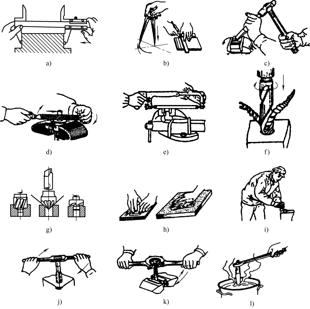
As shown in Figure 12, basic bench work operations include: part measurement, marking, chiseling, filing, sawing, drilling, countersinking, thread tapping and threading, riveting, scraping, as well as straightening and bending, grinding, and simple heat treatment.

a) Measurement
b) Marking
c) Chiseling
d) Filing
e) Sawing
f) Drilling
g) Countersinking
h) Grinding
i) Scraping
j) Thread tapping
k) Threading
l) Simple heat treatment
m) Straightening and bending
n) Riveting
V. Safety requirements for bench work operations
To ensure the safety of bench work, all personnel engaged in bench work must understand and master the general safety requirements for bench work, which include the following:
- Strictly follow labor discipline and relevant safety operation procedures. When practicing, you must wear proper work clothes, work caps, and other necessary protective equipment.
- The workplace should be clean and tidy, tools and measuring instruments should not be mixed, and objects should be placed stably.
- Do not use unfamiliar equipment and tools without authorization.
- Use a brush to remove metal chips; do not remove them by hand, and especially do not blow them away with your mouth.
- Be cautious of electric shock when using electrical equipment and knife switches. Turn off the power supply promptly after use.
- Inspect equipment before use and report any problems immediately.
- If personal injury or equipment accidents occur, report them immediately and handle them promptly. Do not conceal them to prevent the accident from escalating.

