I. Basic Process Knowledge
1. Concept and Applications of Chiseling
The method of cutting metal workpieces using a hammer to strike a chisel is called chiseling.
Chiseling is mainly used in areas that are inconvenient for mechanical processing but convenient for manual processing, such as removing flanges and burrs from castings, cutting materials, chiseling flat surfaces and grooves. Through the hammer-wielding exercise of chiseling work, the accuracy of hammering can be improved, laying a solid foundation for assembling and disassembling mechanical equipment.
2. Chiseling Tools
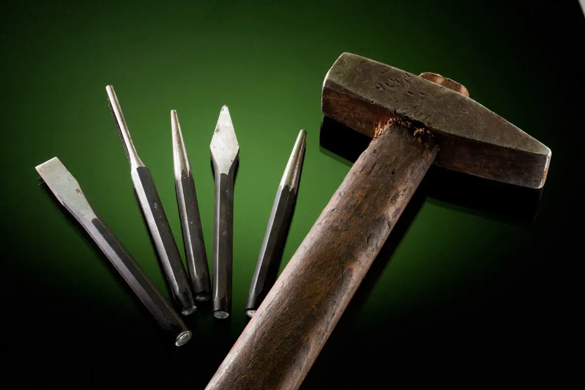
The main tools used for chiseling are chisels and hammers.
(1) Chisel
1) Types and Uses of Chisels
The chisel is the cutting tool used in chiseling, generally made of carbon tool steel.
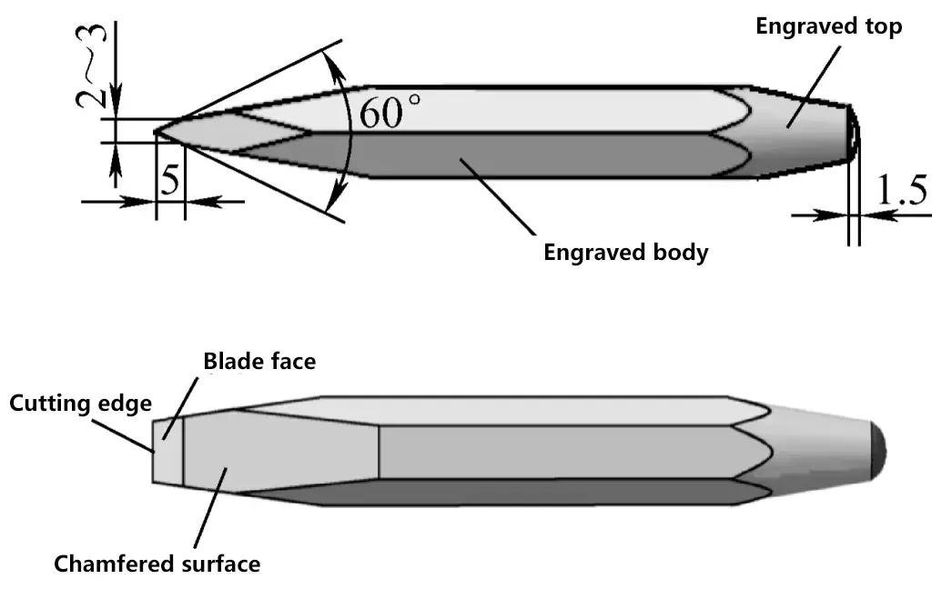
A chisel consists of three parts: the head, cutting part, and body, as shown in Figure 1. The head has a certain taper, with a slightly spherical top, making it easier for the force to pass through the center line of the chisel during hammering, keeping the chisel stable. Most chisel bodies are now hexagonal to prevent rotation during chiseling.
Chisels are divided into three types: flat chisels, groove chisels, and oil groove chisels. Their uses are as follows:
① Flat Chisel
Flat chisels, also known as wide chisels, are mainly used for chiseling flat surfaces, cutting small-sized round steel, flat steel, and thin steel plates. Figure 1 shows the dimensions and names of each part of a flat chisel. The blade width of a flat chisel is generally 10-20mm.
② Groove Chisel
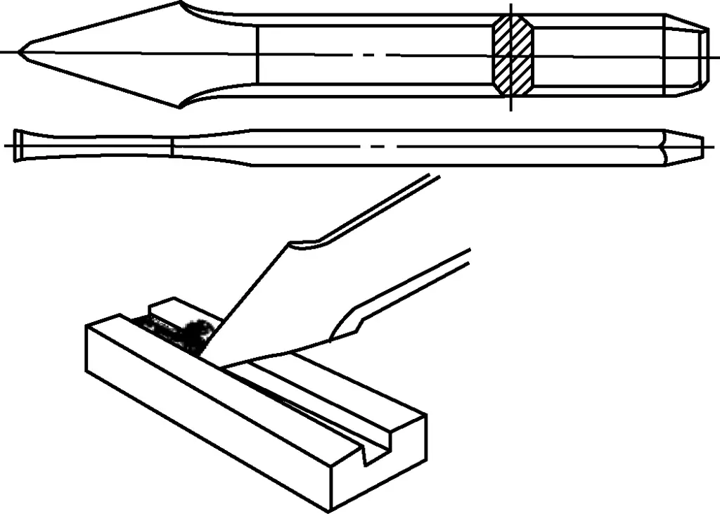
Groove chisels, also known as pointed chisels or narrow chisels, are mainly used for carving grooves, keyways on metal surfaces, and cutting curved sheet metal. The blade width of a groove chisel is determined by the groove width, generally about 5mm, as shown in Figure 2. When chiseling a large flat surface, first use a groove chisel to make grooves, then use a flat chisel to flatten, as shown in Figure 3.

③ Oil Groove Chisel
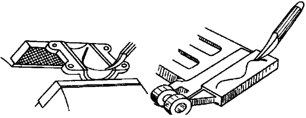
Oil groove chisels are mainly used for chiseling oil grooves, such as chiseling oil grooves in shaft bearings and other sliding surfaces. Its cutting edge should be ground into an arc shape that matches the oil groove shape, with a width equal to the oil groove width, and the oil groove is chiseled along the scribed line on the workpiece. The oil groove should be chiseled smoothly and with consistent depth. The chiseling method is shown in Figure 4.
2) Working Angles of Chisels
The main factors affecting the quality and efficiency of chiseling are the wedge angle of the chisel and the back angle during chiseling.
Selection of wedge angle β: The chisel is a type of cutting tool, its cutting edge is formed by two edge faces, shaped like a wedge, so the angle formed by the two edge faces is called the wedge angle, denoted as β. A small wedge angle makes the chisel’s edge sharp, but with poor strength and easily chipped. A large wedge angle gives the tool good strength, but with high chiseling resistance and difficulty in cutting, as shown in Figure 5. The size of the wedge angle should be chosen based on the hardness of the workpiece.
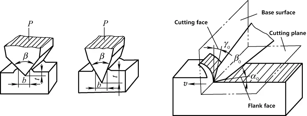
Generally, for chiseling brittle and hard materials, the wedge angle should be larger; for softer materials, the wedge angle should be smaller. The wedge angle for hard materials is 60°-75°; for medium hardness materials, 50°-60°; for copper and cast iron materials, 30°-50°.
Selection of back angle αo: The angle between the back face of the chisel and the workpiece is called the back angle. If the back angle is too large, the chisel will cut too deep into the workpiece. If the back angle is too small, the chiseling direction will be too flat, and the chisel may easily slip off the workpiece surface, also preventing cutting, as shown in Figure 6. Generally, a back angle of 5°-8° is appropriate. During the chiseling process, the back angle should be kept as constant as possible, otherwise the machined surface will be uneven.
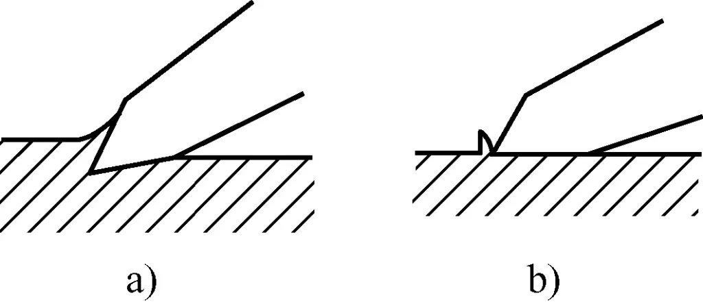
a) αo large
b) αo small
(2) Hammer
1) Hammer Specifications
The hammer shown in Figure 7a, commonly known as a sledgehammer, is one of the most frequently used hand tools in basic bench work and disassembly operations.
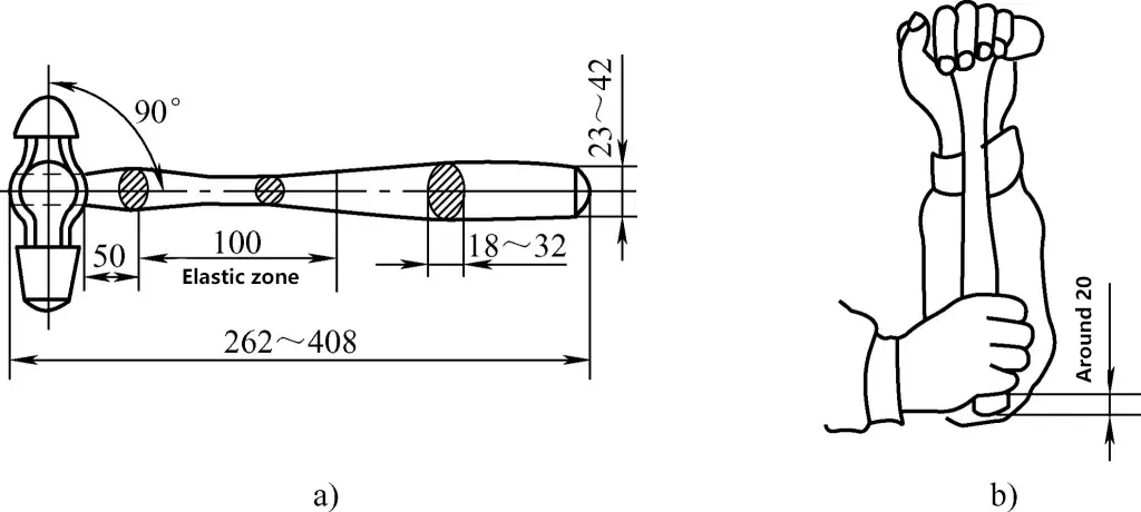
a) Hammer and Handle
b) Determining the Length of the Hammer Handle
A hammer consists of two parts: the hammer head and the wooden handle. The weight of the hammer head is used to indicate the hammer’s specification, with common sizes being 0.22kg, 0.44kg, 0.66kg, 0.88kg, 1.1kg, etc. The hammer head is made of carbon tool steel (T7 or T8) and undergoes hardening treatment.
The hammer handle is made of tough wood, with rosewood being a common choice. The hammer handle is usually about 300-350mm long, with heavier hammer heads requiring longer handles. For example, a 1.1kg hammer head should be fitted with a 350mm long handle. However, it can also be determined based on the length of one’s forearm, as shown in Figure 7b.
2) Hammer Installation
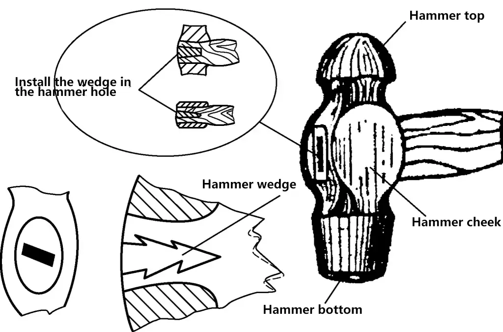
As shown in Figure 8, when installing a hammer, ensure that the centerline of the handle is perpendicular to the centerline of the head; the handle must be securely fixed in the head to prevent accidents caused by detachment. For this reason, the hole for the handle should be oval-shaped. After the handle is tightly fitted into the hole, a wedge is driven into the end to prevent loosening. The handle should also be oval-shaped, allowing for a firm grip and preventing rotation during use, ensuring more accurate hammer strikes.
II. Basic Operational Skills
1. Heat Treatment Process for Chisels
(1) Quenching Process
As shown in Figure 9, heat the cutting part of the chisel, about 20mm in length, evenly to 750-780°C (cherry red color), then vertically place the chisel into cold water (immersion depth about 4-6mm, i.e., the length of the cutting edge), and slowly move the chisel to quench it.
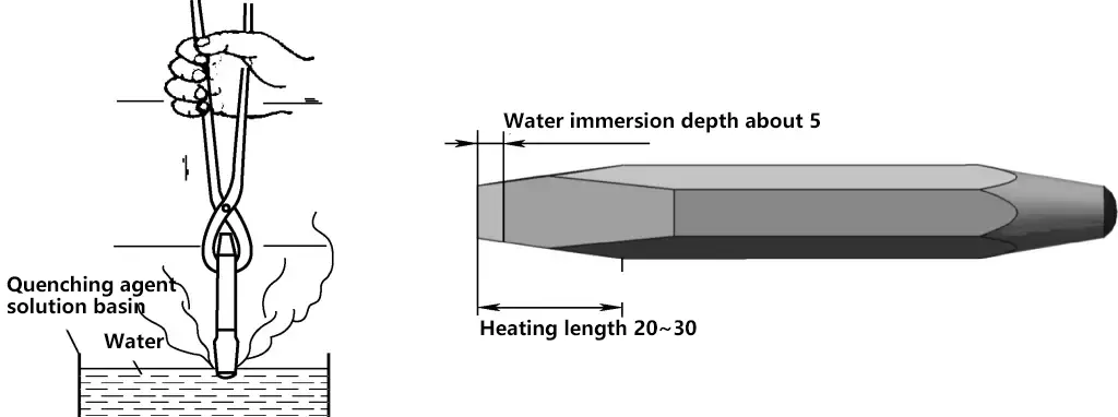
If kept stationary, the boundary between the quenched and unquenched parts will be too distinct, and the chisel may easily break at the boundary during use after quenching.
(2) Tempering Process for Chisels
While moving during quenching, when you observe that the part of the chisel above the water surface has changed from red to black, quickly remove the chisel from the water, immediately remove any dirt and scale (using the residual heat from the upper part of the chisel to temper the cutting edge).
The specific method is to take the chisel out of the water and quickly rub it a few times on a pre-prepared fine grinding wheel or sandpaper (action must be quick), observing the color change of the cutting edge. When the cutting edge turns yellow, immerse the entire chisel in water, known as quenching at “yellow heat”.
“Yellow heat” quenched chisels have high hardness but are brittle, and the cutting edge may chip or even break during chiseling. When the cutting edge turns blue, immerse the entire chisel in water, known as quenching at “blue heat”. “Blue heat” quenched chisels have too low hardness, and the cutting edge may curl during chiseling.
The ideal situation is when the yellow color fades and purple appears, immediately place the entire chisel in water (because the purple color appears for a very short time, if not immersed in water immediately, it will turn blue, becoming the aforementioned “blue heat”). At this time, the quenched chisel not only has relatively high strength and hardness but also good impact toughness.
2. Chisel Sharpening Process
(1) Chisel Sharpening Requirements
1) General Requirements for Tool Sharpening
- The cutting edge should be straight, symmetrical, sharp, without chipping or cracking.
- Grind the correct cutting (working) angles.
- The tool’s cutting edge length and cutting surface area should meet requirements; the cutting edge should not be too long, and the cutting surface area should not be too large.
- The cutting surface (working surface) should be flat, symmetrical, smooth, without curved surfaces or multiple facets.
- The part of the tool for gripping or clamping should have the correct shape for easy holding or clamping; there should be no cracks, burrs, or chipping.
2) Specific Requirements for Chisel Sharpening
In addition to meeting the above general requirements for tool sharpening, chisel sharpening should also achieve the following points:
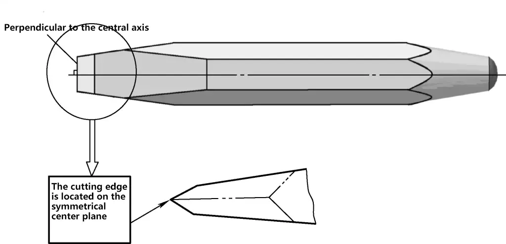
- Correctly choose the chisel’s wedge angle based on the material to be processed.
- The width of the cutting edge should be about 5mm.
- As shown in Figure 10, the cutting edge should be perpendicular to the centerline of the chisel body and should be on the symmetrical center plane of the chisel.
- For unground blank chisels, the beveled face and both sides of the chisel should be trimmed. The trimming method and requirements are basically the same as those for grinding cutting surfaces.
- If the chisel top shows unevenness, a “mushroom head”, or accumulation of burrs and fins, it must be trimmed on the grinding wheel to the required shape.
- In addition to meeting the above sharpening requirements, the cutting edge of a flat chisel can be slightly curved. This is useful when chiseling small protrusions on a flat surface, as the pointed corners at both ends of the cutting edge are less likely to damage other parts of the flat surface.
- In addition to meeting the above sharpening requirements, the cutting edge length of a pointed chisel should correspond to the groove width. The width between the two sides should gradually narrow from the cutting edge towards the handle to avoid the chisel getting stuck when chiseling grooves and to ensure that the sides of the groove can be chiseled flat.
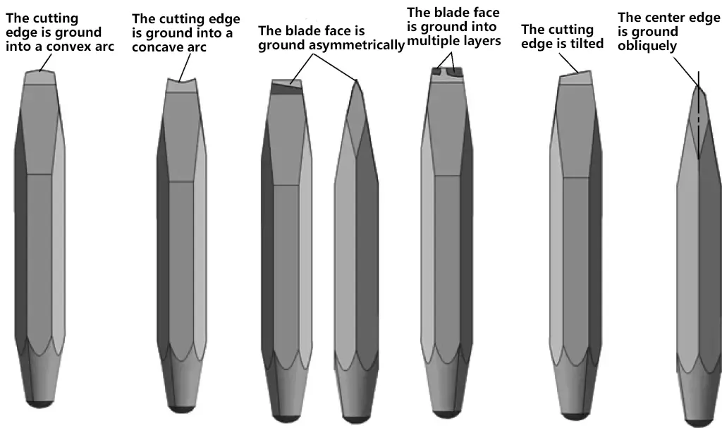
- Common sharpening errors when grinding chisels are shown in Figure 11.
(2) Chisel Sharpening Methods
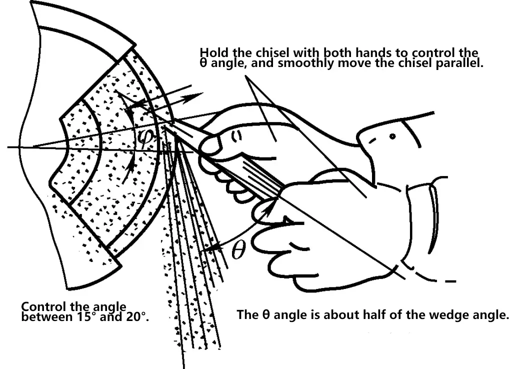
The basic method for sharpening chisels is shown in Figure 12.
- Strictly follow the safety operating procedures for grinding machines.
- When sharpening a chisel, the operator should stand on the left side of the grinding machine, hold the front end of the chisel with the thumb and index finger of the right hand, firmly grip the chisel body with the left hand, and perform the sharpening on the edge of the rotating grinding wheel.
- During sharpening, the cutting edge must be higher than the horizontal center line of the grinding wheel. Move smoothly and evenly across the full width of the wheel, and control the direction and position of the chisel to ensure the desired wedge angle is ground.
- The pressure applied to the chisel during sharpening should be moderate, neither too large nor too small. If the pressure is too high, the chisel will inevitably vibrate, causing chatter marks during sharpening and possibly multiple facets; if the pressure is too low, the surface will not be easily ground flat, and the grinding efficiency will be low.
- When sharpening the cutting edge, frequently dip it in water to prevent tempering of the cutting edge.
- After sharpening, the quality can be checked using a special template, as shown in Figure 13.

the Sharpening Quality of a Chisel
3. Chiseling Operation
(1) Methods of Holding a Hammer
There are two methods of holding a hammer: loose grip and tight grip.
1) The tight grip method involves the index finger, middle finger, ring finger, and little finger of the right hand tightly gripping the hammer handle, with the thumb pressed against the index finger, leaving 15-30mm of the handle exposed at the end. The grip remains unchanged during swinging and striking. The tight grip method is rarely used because it can easily cause blisters on the hand due to the firm grip, as shown in Figure 14a.

a) Tight grip method
b) Loose grip method
2) The loose grip method is to always hold the hammer handle with the thumb and index finger. When the hammer is raised backwards (during the swing process), gradually relax the little finger, ring finger, and middle finger, naturally pressing against the hammer handle.
During the hammering process, gradually tighten the relaxed fingers and accelerate the hammer’s movement. Once mastered, this method can not only increase the hammering force but also reduce fatigue, so the loose grip method is better than the tight grip method, as shown in Figure 14b.
(2) Chiseling posture and hammer swinging method
1) Standing posture
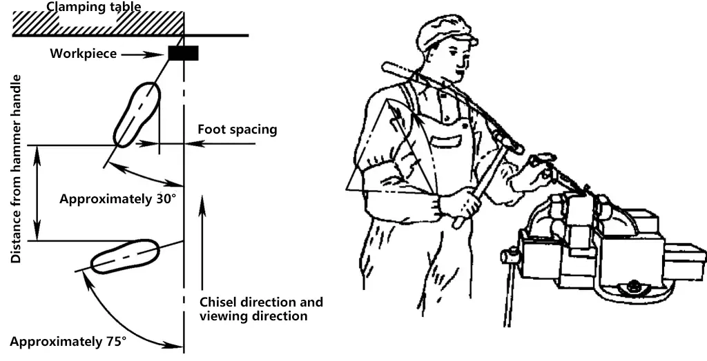
The correct standing posture is to facilitate force application during chiseling and to prevent fatigue throughout the body. Usually, the left foot is half a step forward, the right foot is behind, the distance between the two feet is about one hammer handle length, with the center of gravity on the left foot, standing stably near the bench vise.
Don’t exert too much force on the legs, slightly bend the left knee, keep the right leg straight and stable, and position the feet in a “V” shape. Don’t lean the head forward or backward, face the workpiece, and look at the chisel edge. The specific standing posture is shown in Figure 15.
2) Hammer swinging method
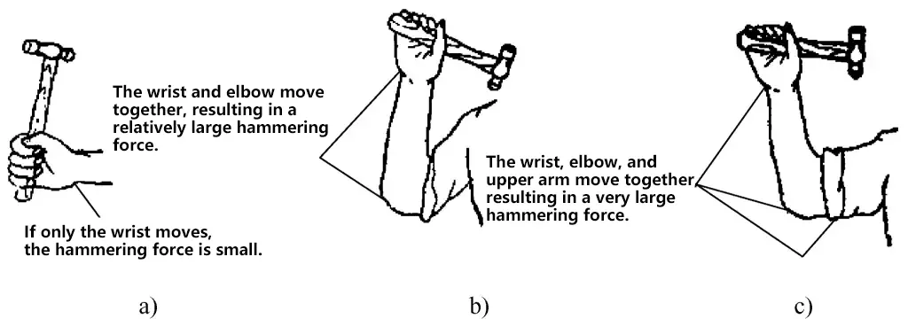
There are three hammer swinging methods: wrist swing, elbow swing, and arm swing, as shown in Figure 16.
a) Wrist swing
b) Elbow swing
c) Arm swing
The wrist swing method is usually used at the beginning and end of chiseling; the elbow swing is most widely used, suitable for chiseling flat surfaces and grooving; the arm swing is mainly used for cutting metal and removing nuts.
3) Key points of hammer swinging action
① Lifting the hammer
Raise the shoulder and pull in the elbow, lifting the hammer above the shoulder; flip the wrist back, loosely grip the hammer handle; the hammer face should be facing upwards.
② Swinging the hammer
Focus your gaze on the chisel edge and the area being chiseled, tighten the grip on the hammer handle, apply force with the wrist, swing the hammer in an arc within the vertical plane (don’t let the arm swing outwards, and don’t let the hammer fall at an angle), striking the top of the chisel directly.
③ Hammering requirements
The hammering frequency should be about 40 times per minute; the strikes should be powerful and accurate; there should be no “tapping” phenomenon (lightly tapping the chisel top to aim before striking with force).
(3) Key points of chiseling operation
1) Chisel gripping methods
① Normal grip method
As shown in Figure 17a, palm facing down, grip the chisel body with the thumb and index finger naturally spread, the other three fingers naturally bent and close together, holding the chisel body. The top of the chisel should protrude 10-15mm from the grip. If it protrudes too much, the chisel may wobble, affecting the accuracy of the hammer strike. The grip should be neither too tight nor too loose, aiming for ease of operation and minimal fatigue. This gripping method is the basic method, suitable for chiseling flat surfaces.

a) Normal grip method
b) Reverse grip method
c) Vertical grip method
② Reverse grip method
As shown in Figure 17b, palm facing up, fingers naturally pinching the chisel body, palm suspended. This grip is suitable for chiseling small flat surfaces or side surfaces.
③ Vertical grip method
As shown in Figure 17c, thumb web facing up, thumb on one side of the chisel, the other four fingers on the other side pinching the chisel. This grip is suitable for vertical chiseling, such as cutting materials on an anvil.
2) Key points for flat surface chiseling operation
① Starting and ending chiseling method.
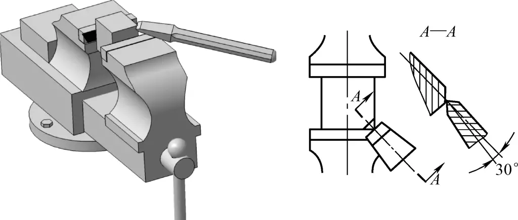
As shown in Figure 18, when chiseling a flat surface, generally use the angled starting method. Begin chiseling from the right corner of the workpiece, first hold the chisel at a 45° angle to the right, then tilt the chisel top down about 30°. When the chisel edge has cut 0.5-1.5mm deep, raise the chisel top to the required back angle and continue chiseling.
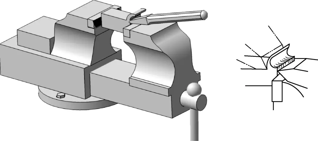
As shown in Figure 19, when chiseling reaches the end of the workpiece (about 10mm from the edge), turn around to chisel the remaining part, otherwise, the edge of the workpiece may chip.
② Chiseling thickness.
After determining the chiseling allowance and marking the processing line, chisel in layers, with each layer typically 0.5-1.5mm thick.
③ Chiseling back angle.
As shown in Figure 20, during chiseling, the angle between the back face of the chisel and the cutting plane (the plane tangent to the cutting edge at a point on the cutting surface) is called the chiseling back angle (denoted by α). The chiseling back angle is generally best at 5°-8° and should remain constant throughout the chiseling process.
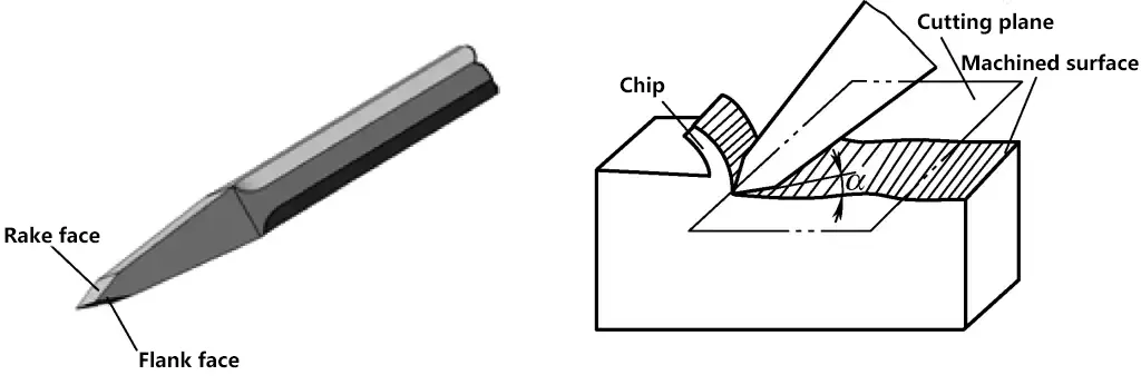
④ During the chiseling process, after every few chisels, you can pull back the chisel slightly, pause briefly, then press the chisel edge against the chiseled area and continue chiseling. This allows you to observe the flatness of the chiseled surface and rhythmically relax your muscles.
3) Sheet metal cutting method
The correct sheet metal cutting method is shown in Figure 21.
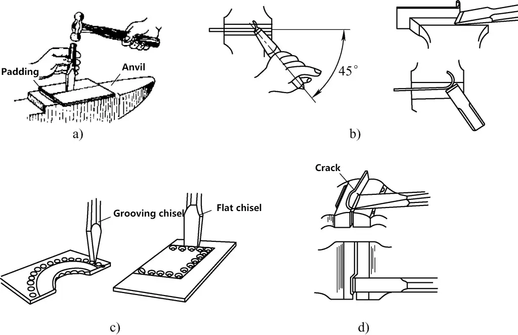
a) Cutting sheet metal on an anvil
b) First drill holes, then use a chisel to cut the sheet metal
c) Correct method of cutting sheet metal on a bench vise
d) Incorrect method of cutting sheet metal
① Figure 21a shows cutting sheet metal laid flat on an anvil. This method is generally used for cutting larger areas or thicker (over 4mm) sheet metal, as well as sheet metal that is inconvenient to clamp in a bench vise. With this method, it’s harder to maintain a straight cut.
Figure 21b shows that clamping the sheet metal on the bench vise jaws for chiseling can more easily obtain a straight cutting edge.
When chiseling workpieces with more complex contours and greater thickness, to avoid deformation during chiseling, first drill separation holes along the outline using a smaller diameter drill bit, then use a pointed chisel to connect the small holes, and finally chisel through. This way, the desired shape can be chiseled out, as shown in Figure 21c.
Figure 21d shows an incorrect method of chiseling sheet metal.
(4) Safety requirements for chiseling
- Do not use hammers with cracked or loose handles.
- Do not wear gloves while chiseling, and wear protective goggles.
- Do not chisel facing towards people to prevent flying chips from causing injury.
- When burrs are found on the chisel head, they should be ground off promptly.

