I. Drive Selection Process
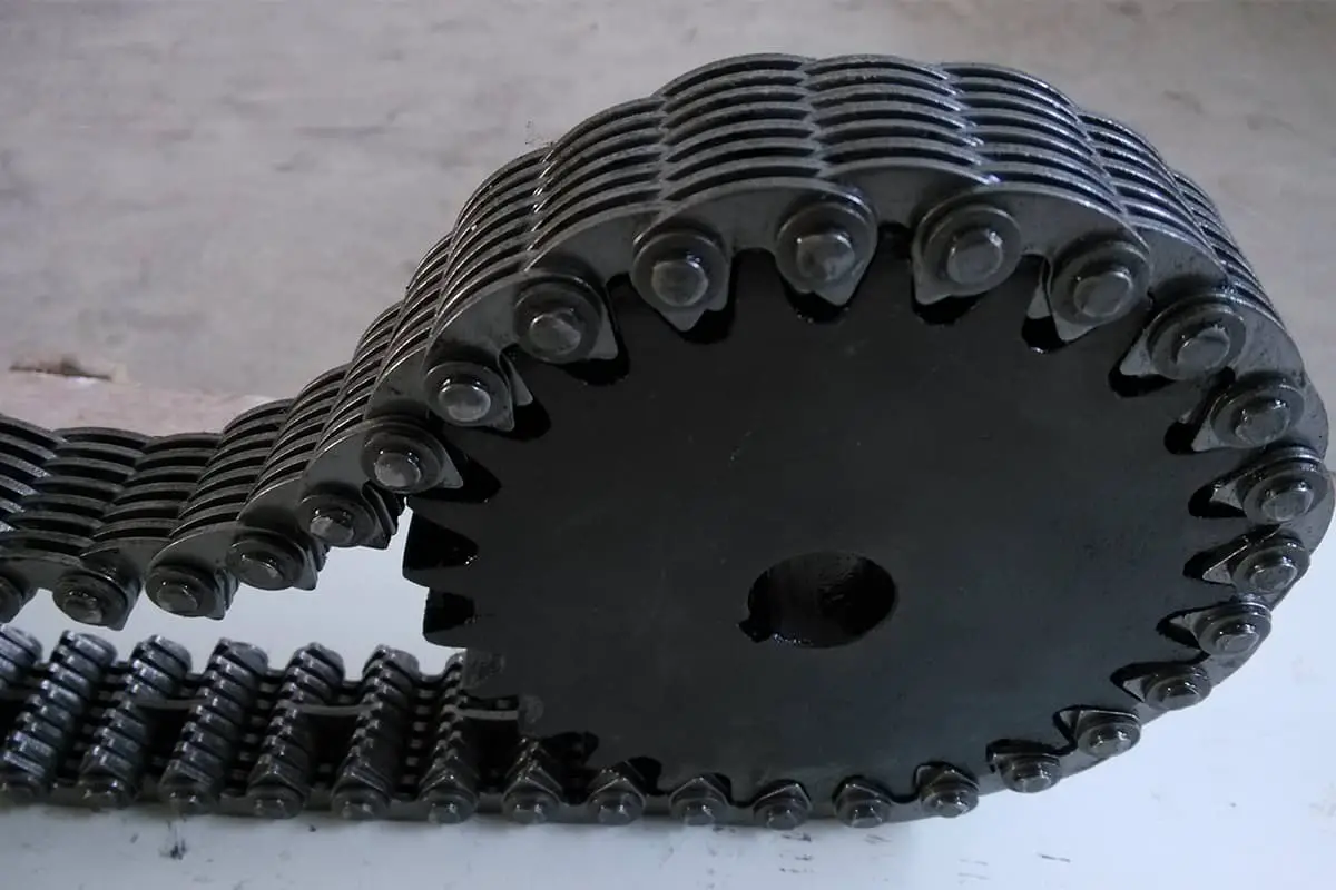
When selecting a toothed chain drive, the combination of chain and sprocket must be chosen to best meet the requirements. In most cases, this is a multi-step process, the first step is to know the installation space for the chain and sprocket as well as the working load and speed requirements.
Usually, for a given working condition, there is more than one size combination of chain and sprocket, so it is best to actually consider two to three alternative plans, and take into account other important factors, such as cost, inventory utilization, and expected lifespan.
Most chain manufacturers provide drive selection manuals and technical support to help users choose products. Some also provide computer programs to simplify the selection process. When the selected drive involves a significant expenditure of funds or works under abnormal and extreme conditions, it is essential to consult the chain manufacturer for assistance.
II. Chain Pitch
Generally speaking, small pitch chains run smoothly at high speeds. Large pitch chains transmit greater torque, but at lower speeds.
III. Chain Width
The rated power of toothed chains is expressed in terms of unit chain width power value. For any given pitch, increasing the chain width increases the strength of the chain. The rated power increases, and so does the cost. When several chain widths meet the specified requirements, the chain with the smaller width is generally chosen to reduce costs. However, increasing the chain width can make the drive more reliable and shock-resistant.
IV. Working Condition Factor
Table 1 provides the working condition factors. Working condition factors are used to characterize the load characteristics of the power source and the driven equipment. When selecting a toothed chain drive, the appropriate working condition factor must be used to obtain satisfactory transmission performance and working life. Incorrect use of working condition factors can lead to premature damage to the drive device.
Table 1 Working Condition Factors
| Application | Prime Mover Type | ||
| A | B | ||
| Mixer | Fully Hydraulic | 1.1 | 1.3 |
| Hydraulic, Variable Density | 1.2 | 1.4 | |
| Bakery Equipment | Dough Mixer | 1.2 | 1.4 |
| Brewing and Filling Equipment | Bottling Machine | 1 | 1.2 |
| Boilers, Cookware, Mash Tuns | 1 | 1.2 | |
| Hopper scale (frequent startup) | 1.2 | 1.4 | |
| Brick and pottery machinery | Screw feeder, cutting table | 1.3 | 1.5 |
| Brick machine, dry press, granulator | 1.4 | 1.6 | |
| Mixing, stirring, rolling machines | 1.4 | 1.6 | |
| Centrifuge | 1.4 | 1.6 | |
| Compressor | Centrifugal and rotary | 1.1 | 1.3 |
| Reciprocating (1 cylinder or 2 cylinders) | 1.6 | 1.8 | |
| Reciprocating (3 cylinders or more) | 1.3 | 1.5 | |
| Crane | Main lifting mechanism (medium load) | 1.2 | 1.4 |
| Main lifting mechanism (heavy load) | 1.4 | 1.6 | |
| Crusher | Ball mill, roller machine, jaw crusher | 1.6 | 1.8 |
| Dredger | Conveying mechanisms, hoisting drums | 1.4 | 1.6 |
| Clamps, screens | 1.6 | 1.8 | |
| Fans and blowers | Centrifugal, propeller, blade type | 1.3 | 1.5 |
| Positive displacement blower | 1.5 | 1.7 | |
| Grain milling machinery | Screening, purification, separators | 1.1 | 1.3 |
| Grinding and hammer mills | 1.2 | 1.4 | |
| Roller mill | 1.3 | 1.5 | |
| Generators and exciters | 1.2 | 1.4 | |
| Machine tools | Boring machines, milling machines | 1.1 | 1.3 |
| Grinders, lathes, drilling machines | 1 | 1.2 | |
| Mixers, Yankee dryers | 1.3 | 1.5 | |
| Calenders, dryers, paper machines | 1.2 | 1.4 | |
| Trimmers, winders | 1.5 | 1.7 | |
| Peeling machines, machinery | 1.6 | 1.8 | |
| Printing machinery | Letterpress printing machines, lithographic printing machines, folding machines | 1.2 | 1.4 |
| Scoring machines, paper cutting machines, rotary printing presses | 1.1 | 1.3 | |
| Magazine, newspaper printing machines | 1.5 | 1.7 | |
| Pumps | Centrifugal pumps, gear pumps, cam pumps, vane pumps | 1.2 | 1.4 |
| Slurry pumps | 1.6 | 1.8 | |
| Pipeline pump | 1.4 | 1.6 | |
| Piston pump (1 cylinder or 2 cylinders) | 1.6 | 1.8 | |
| Piston pump (more than 3 cylinders) | 1.3 | 1.5 | |
| Rubber and plastic machinery | Calender, roll machine, pipe making, tire cord laminating machine | 1.5 | 1.7 |
| Banbury mixer | 1.5 | 1.7 | |
| Mixer | 1.6 | 1.7 | |
| Extruder | 1.5 | 1.8 | |
| Screening machine | Cone, rotary | 1.2 | 1.4 |
| Rotary, gravel, stone, vibrating type | 1.5 | 1.7 | |
| Automatic coal feeder | 1.1 | 1.3 | |
| Textile industry | Drop cloth frame, calender, loom | 1.1 | 1.3 |
Prime mover type A: Hydraulic transmission for internal combustion engines, torque converters, electric motors, turbines, or hydraulic motors.
Prime mover type B: Mechanical transmission for internal combustion engines.
V, number of sprocket teeth
To ensure long-life transmission and smooth operation, the sprocket should have at least 21 teeth. Using sprockets with fewer teeth in the transmission may increase vibration and noise due to the polygon effect. Each sprocket hub must have a sufficient diameter size to machine the assembly shaft hole and keyway. Table 2 provides the maximum recommended hole diameter sizes for standard toothed chain sprockets with 33 teeth or less.
ANSI toothed chain sprockets must not have less than 12 teeth, and the number of teeth on large sprockets generally should not exceed 120 teeth.
After the toothed chain wears, the actual pitch increases, placing the chain at a larger pitch circle on the wheel teeth. When the elongation is too great, the chain may start to skip or fall off, damaging the chain and sprocket. The maximum allowable elongation (%) of the chain is 200/N, where N is the number of teeth on the large sprocket.
Table 2 Maximum Hole Diameter for Standard Tooth Chain Sprockets (Unit: in)
| Number of Teeth | Hole with Standard Keyway Chain Pitch | ||||||
3/8 | 1/2 | 5/8 | 3/4 | 1 | 11/2 | 2 | |
| 17 | 7/8 | 13/8 | 13/4 | 21/16 | 23/4 | 41/8 | 51/4 |
| 19 | 11/4 | 15/8 | 2 | 23/8 | 31/4 | 43/4 | 6 |
| 21 | 15/16 | 17/8 | 25/16 | 23/4 | 33/4 | 51/2 | 7 |
| 23 | 11/2 | 21/8 | 25/8 | 31/4 | 41/4 | 61/2 | 73/4 |
| 25 | 13/4 | 23/8 | 215/16 | 35/8 | 43/4 | 73/8 | 87/8 |
| 27 | 17/8 | 25/8 | 31/4 | 315/16 | 55/16 | 77/8 | 95/8 |
| 29 | 21/16 | 213/16 | 35/8 | 43/8 | 59/16 | 9 | 105/8 |
| 31 | 21/8 | 31/16 | 313/16 | 41/2 | 65/16 | 915/16 | 111/8 |
| 33 | 25/16 | 31/4 | 41/4 | 415/16 | 615/16 | 1011/16 | 123/8 |
VI. Sprocket Tooth Hardening Treatment
To maximize transmission life, sprocket teeth should be hardened. However, in some cases, such as when the sprocket is large, with more than 50 teeth, and both the load and speed are low, non-hardened teeth can also provide good life.
VII. Small Sprocket Chain Wrap Angle
To ensure normal engagement and prevent chain jumping, the chain wrap angle of the small sprocket should be at least 120°. If the drive ratio is 3:1 or smaller, this requirement is naturally met. The chain wrap angle is calculated using the formula below.
A=180°-2arcsin[(D-d)/2C]
Where
- A is the chain wrap angle (°);
- D is the large sprocket diameter (in);
- d is the small sprocket diameter (in);
- C is the center distance (in).
VIII. Drive Ratio
The drive ratio of a toothed chain can reach 12:1, but a drive ratio below 8:1 is usually more economical and practical. Ratios higher than this often require a two-stage drive.
IX. Chain Length
The total number of links in the chain should be even. When using an odd number of links, a transition link must be used, which will reduce the transmission capacity and increase the cost. Various types and widths of toothed chains cannot use transition links.
X. Axle Center Distance
If the center distance is not predetermined, it is best to ensure that the small sprocket wrap angle is at least 120°, or take the minimum value according to other practical application conditions. Because for a given drive ratio, a shorter center distance requires a shorter chain, which can reduce the number of parts subject to wear and lower costs. A longer center distance means a longer chain, which may cause vibration and accelerate wear, making maintenance more difficult.
XI. Minimum Center Distance
The minimum center distance should ensure that the two sprockets do not interfere, and it must be able to make the small sprocket chain wrap angle reach 120°. To prevent the sprockets from interfering, the center distance should be greater than the sum of the radii of the two sprockets’ outer circles. If the drive ratio is 3:1 or smaller, the center distance can be as large as needed, and the small sprocket wrap angle will meet the standard. For larger drive ratios, the chain wrap angle should be calculated using the formula mentioned earlier when selecting the center distance.
XII, Practical Center Distance
Generally, the center distance should not exceed the length of 60 chain links. If the center distance is too large, the sag of the chain will be excessive.
XIII, Adjustable Center Distance
The center distance should be made adjustable whenever possible, so that the chain can be retensioned after wear to ensure normal transmission. An estimate of the required adjustment for a given drive is to multiply the maximum permissible elongation rate by the initial center distance, and to make the adjustment as close to the length of two chain links as possible.
XIV, Fixed Center Distance
When the center distance can only be fixed and tensioning devices such as chain tensioning wheels or other methods cannot be used, it is particularly important to maintain an appropriate tension in the chain during drive design. A typical practice is to strictly control the length of the chain and the center distance of the sprockets used. Sometimes, chain manufacturers recommend slightly increasing the precise center distance to ensure that the chain has the proper tension after a brief trial run.
When using chains, it is generally advisable to choose a chain wider than required, which can effectively reduce the stress on the chain hinges, decrease the wear rate, and extend the service life of the fixed center distance drive. For fixed center distance drives, specific recommendations can be sought from chain manufacturers.
XV, Chain Sag Space
After the chain wears and elongates, the sag on the slack side of the chain will increase. It is necessary to ensure that there is enough space around the drive device to accommodate the wear.
XVI, Chain Idler
To maintain proper chain tension, an idler or a shoe-type tensioning device can be used on the slack side of the chain. The idler must be installed on the inside of the drive, while the shoe must be installed on the outside. Before using a shoe tensioner, confirm that the sprocket chain used is compatible. Many sprocket chains do not have a “backbend” design, which can cause serious damage to the shoe.
XVII, Drive Arrangement
Common drive arrangements have been introduced in previous articles.
1. Variable Speed Drive
When the drive operates within a certain range, it is necessary to ensure that the chain has the capacity to work under maximum load and speed. Sometimes, the load cycle (the percentage of working time under different loads and speeds) is very clear, and it must be taken into account for the expected chain life requirements before finally selecting the chain.
2. Multiple Driven Sprockets
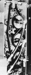
When there are multiple driven sprockets (see the figure below), double-sided sprocket chains are often used, which can drive sprockets on both sides of the chain. Double-sided sprocket chains come in various forms, and chain manufacturers should be consulted when designing double-sided sprocket chain drives.
