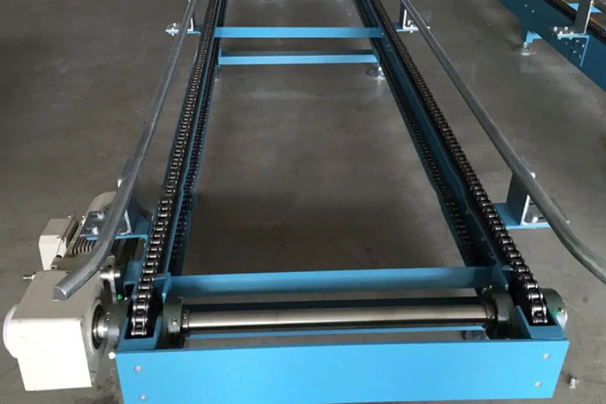
I. Conveyor Type
Designers must consider choosing one of two types of conveying modes, which are:
(1) The material is completely supported and carried by the chain and attachments. Support-type, skirt-type, chute-type, slat-type, cross-bar-type, and floor-type conveyors all belong to this category.
(2) The material slides along the conveyor surface under the push of baffles or other attachments, with the chain not supporting the conveyed material. Push-type and scraper-type conveyors belong to this category.
The final choice of conveyor type also depends on the following conditions:
- The advantages and disadvantages of each application type.
- Initial installation and daily costs.
- Required working life and maintenance costs.
- Conveyor speed.
- Conveyor length.
- Loading method.
For uncommon or complex conveyors, it is essential to consult roller chain manufacturers, as more experience is needed to make a better choice in such cases.
II. Conveyor Width and Height Space
The conveyor must have sufficient width to place items or transport materials, and must also have enough height space to allow attachments, fixtures, and conveyed items to pass through. At the same time, there must be enough height space for the unloaded attachments and fixtures to return. Designers must carefully consider all physical condition restrictions before determining the size of the chain conveyor.
III. Conveyor Length and Shaft Center Distance
The length of the conveyor is affected by the frictional resistance of the dragging chain and the weight of the conveyed material, as well as the rated power limit of the chain. The greater the conveying length, the greater the dragging force required, and the smaller the relative carrying capacity for the conveyed material.
The center distance of the drive shaft is usually equal to the length of the conveyor, but sometimes it is longer because auxiliary loading and unloading devices placed at both ends of the conveyor require an increased center distance.
IV. Conveyor Loading
Any conveyor loading process should be as smooth as possible to avoid impact. If possible, conveyor loading should be done using positioning and sliding methods to reduce the fluctuations of shaking and rough loading. The chutes or hoppers used to load the conveyor should be positioned as much as possible in the middle of the two conveyor chains, otherwise one side of the conveyor chain may wear out faster than the other.
V. Conveying Capacity
Conveying capacity is the amount of material (by weight or number) that a conveyor transports in a unit of time, and it is calculated using the following formula:
Wc=60WS
Where
- W is the conveying capacity (lbf/h or pieces/h);
- W is the amount of conveyed material (lbf/ft or pieces/ft);
- S is the conveying speed (ft/min).
VI. Conveying Speed
The required conveying capacity determines the conveying speed, which is limited by the type of material being conveyed, the method of conveyance, and the loading and unloading methods.
VII. Accumulation
Sometimes users need to temporarily stop the transport of items without stopping the conveyor, which requires accumulation space. Accumulation spaces are often used in pusher-type and scraper-type conveyors.
By using a certain device to raise the goods or lower the chain, the goods are placed on the platform or fixed belt, while the conveyor chain below the goods continues to operate as usual. Suspending the goods in this way does not increase the chain tension, but actually reduces it.
Sometimes there are backlog sections in slat conveyors, where the device holds the goods in place while the conveyor belt slides under the goods. Stopping the goods in this way greatly increases the chain tension, so the backlog section should be as short as possible. Continuous operation conveyors generate a lot of heat when backlogging goods, so the backlog time should be as brief as possible.
VIII. Types of Chains
1. Precision Roller Chains
Precision roller chains with attachments are often used in conveyors. These chains and the standard attachments used are shown in ASME B29.1. Some manufacturers offer precision roller chains for conveyors with straight side plates. Precision roller chains are usually used when sprocket sizes are limited or when high transmission smoothness is required.
2. Double-Pitch Roller Chains for Conveyors
Double-pitch roller chains for conveyors are also used in conveyors. These chains and the standard attachments used are shown in ASME B29.4. The double-pitch roller chains for conveyors have straight side plates, with rollers available in large and small diameters.
Small diameter roller chains are usually used in vertical conveyors or short-distance conveyors, where the chain runs by sliding along the edge of the chain plate. Large diameter roller chains are usually used for long-distance conveying to reduce frictional force.
3. Hollow Pin Roller Chains
Hollow pin chains are almost exclusively used in crossbar conveyors. Hollow pin chains also come in single-pitch and double-pitch types, with rollers available in large and small diameters.
IX. Chain Pitch
Conveyor chain selection is usually based on the working load, with the chain working load corresponding to the pitch. In addition, the size of the conveyed items and the space required for attachments are also restricted by the pitch. Short-pitch chains (35-80) are generally used for short-distance conveyors or when smooth operation is required. Large-pitch chains (100-200, or c2040-c2160) are usually used for long-distance conveyors with relatively low speeds.
X. Chain Attachments
Figure 1 shows some specialized attachments, while Figures 2 and 3 show the use of attachments.
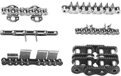
Figure 2 shows the attachment installation for single-row chains. On the left side of the figure, V-blocks are attached with A-1 and M-1 attachments, which are often used to convey cylindrical objects. The upper and middle pictures in the center part of the figure show chains with rollers attached using M-1 and D-1 attachments. Rollers installed with M-1 attachments allow the conveyed items to “press down” on the chain for rolling friction contact, while rollers installed with D-1 attachments are usually to support the chain by rolling friction.
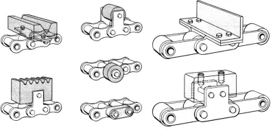
The lower picture in the middle shows rubber blocks installed with D-3 attachments, giving it a high-friction conveying surface. The upper right picture shows angle irons connected with K-2 attachments to form push plates. The lower right picture shows a chain with M-2 attachments installed with threaded bearing blocks.
Figure 3 shows three types of double-chain combinations. The left picture shows slats installed with A-1 attachments. The middle picture uses M-35 attachments as spacers and locators for transporting long items. The right picture shows long tubes installed with D-3 attachments as a conveying surface, which can also be achieved with hollow pin chains and extended crossbars.

XI. Conveyor Chain Support
Generally, multiple carrying chains are supported by tracks or guide rails. If the conveyor chain has large diameter rollers, the roller chain is usually supported by the rollers running in the tracks; if the conveyor chain has small diameter rollers, the roller conveyor chain usually relies on sliding along the bottom edge of the chain plate. When the conveyor chain has small diameter rollers, the load-bearing edge of the chain should not be supported by rollers, as this may cause the rollers to not rotate and become flattened.
When the center distance of the drive exceeds 80 chain links, the return side of the conveyor chain should be supported, because an unsupported return side that is too long will sag and can greatly increase the chain tension. Usually, the chain tension is greatly reduced after the return side is supported.
In addition, the sagging of the return side can sometimes cause “sticking” obstructions due to wear and elongation, which would not occur in new conveyors. Supporting the return side can also reduce fluctuations and swaying.
In most conveyors, the return side is returned by sliding the chain plate edge on the guide rail or by sliding the mounting parts on the platform. Even for large diameter roller chains, the return side is returned by sliding on the track or platform, because the chain attachments or their mounting parts usually prevent the rollers from functioning on the return side.
XII. Conveyor Drive
The power of the conveyor should be placed at the head shaft to drive, which is usually at the unloading end of the conveyor, so that the chain has the maximum tension only on the carrying side when the conveyor chain is working.
Because the wear life of the conveyor chain is a function of load and the duration of the load, if the conveyor is driven by the tail shaft, then both sides of the entire chain are under load, which shortens the relative life. Tail shaft drive also causes the accumulated slack of the chain to pile up at the tail shaft sprocket (see Figure 4), which can cause loading problems for the conveyor or cause the chain to skip teeth on the sprocket.

XIII. Sprockets
1. Sprocket Size
Most conveyors have the same sprocket size at the front and rear shafts. If smoothness is not pursued, for double-pitch chains, a sprocket with 6 effective teeth can be used in very low-speed conveyors. However, more than 15 effective teeth are needed to achieve a relatively ideal transmission effect.
For single-pitch chains, the sprocket should have at least 15 teeth. When high smoothness is required, the sprocket should have 21 teeth or more to reduce the polygon effect. However, if space is limited, the number of teeth should be chosen based on the available space as much as possible.
2. Sprocket Tooth Hardening
Sprocket tooth hardening is mainly considered for the following situations:
- Abrasive environments.
- Use of sprockets with fewer than 15 teeth.
- High speed: speeds greater than 150ft/min
- High load: loads greater than 50% of the rated power.
3. Sprocket Matching
On conveyors with multiple parallel transmission chains, accurate alignment of the head shaft sprockets is extremely important (see Figure 5). Sprockets should be ordered as a set, connected with keys to form a straight line, symmetrically matched and marked.
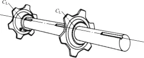
When installing the tail shaft sprockets, one of the sprockets is fixed to the shaft with a key and rotates with the shaft, while the other sprocket is loosely fitted on the shaft, fixed on both sides with retaining rings, and can freely rotate on the shaft to automatically balance the uneven wear between the two chains.
XIV. Tensioning Devices
Most conveyors need tensioning devices to adjust the chain tension. Tensioning devices are devices that adjust the center distance of the shaft, and conveyors generally install tensioning devices at the loading end to adjust the chain elongation due to wear.
Tensioning devices also serve to loosen the chain during chain installation and maintenance. The tensioning device should be adjusted to the optimal working state of the conveyor. There are four basic types of tensioning devices: screw type, spring type, gravity traction type, and chain hanging type. These four types are shown in Figure 6.
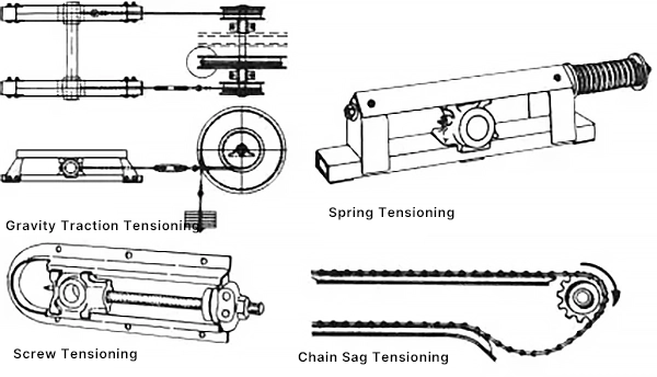
XV. Suspended Tension and Chain Slack Side
In most long-distance conveyors, most of the length of the return side chain should be supported. The weight of the hanging or partially hanging unsupported chain is a factor that cannot be ignored for the entire chain tension, because the total load on the chain will also affect the bearing and shaft load calculations, and the increased tension from this part of the hanging chain is not included in the calculation of conveyor power.
When using tensioning devices, 30-50 chain links can be reserved as an unsupported length to accommodate chain wear elongation. This part of the hanging also ensures that the slack side has sufficient tension to prevent phenomena such as chain skipping under heavy loads.
Adequate sagging space should be provided for the slack side of the chain. If the sag of a long-span chain is too small, it will greatly increase the force on bearings and the chain. The sag of the chain should not be less than 3% of the sagging length.
XVI. Elastic Elongation
Roller chains will undergo elastic changes when subjected to force. If the force is less than the yield strength of the chain, then the chain can almost retract to its original length after the external force is removed. The amount of elastic elongation is calculated using the following two formulas:
For single-pitch chains d=0.15PC/12500p²
For double-pitch chains d=0.15PC/3125p²
Where
- d is the total elastic elongation (in);
- P is the chain tension (lbf);
- C is the conveyor length (ft);
- p is the chain pitch (in).
The amount of elastic elongation for long-distance conveyors will be larger. When the conveying length exceeds 20ft, regardless of what is being conveyed, the elastic elongation must be calculated, and the calculation error must be kept within 0.5in. Elastic elongation must also be calculated when the chain is used for precise stepping.

