I. Spindle Component
The spindle component is a key part of the lathe. During operation, the workpiece or fixture is mounted on the spindle and directly driven by it to rotate as the main motion. Therefore, the rotational accuracy, rigidity, and vibration resistance of the spindle directly affect the machining accuracy and surface roughness of the workpiece.
Figure 1 shows the spindle component of the CA6140 lathe.
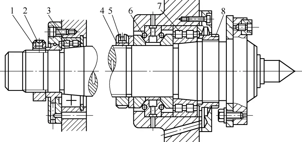
1, 4, 8 – Nuts
2, 5 – Screws
3, 7 – Double-row short cylindrical roller bearings
6 – Double-direction thrust angular contact bearing
To ensure good rigidity and vibration resistance of the spindle, three supports – front, middle, and rear – are used. The front support uses a combination of a double-row short cylindrical roller bearing 7 (NN3021K/P5) and a 60° double-direction thrust angular contact ball bearing 6 (51120/P5), which bear the backward force and left and right feed forces generated during cutting.
The rear support uses a double-row short cylindrical roller bearing 3 (NN3015K/P6). A single-row short cylindrical roller bearing (NU216) is used as an auxiliary support in the middle of the spindle (not shown in the figure). This structure maintains good rigidity and operational stability under heavy load conditions.
As the front and rear supports of the spindle use double-row short cylindrical roller bearings, their inner ring’s tapered hole matches the tapered surface of the shaft journal. When the bearing wears and the radial clearance increases, it is relatively easy to adjust the radial clearance by adjusting the axial position of the spindle journal relative to the inner ring of the bearing.
The middle bearing (NU216) only provides support when the spindle shaft is under significant force and there is some deflection at the middle support. Therefore, there needs to be a certain clearance between the shaft and the bearing.
1. Adjustment method for the front bearing
Use nuts 4 and 8 to adjust. When adjusting, first loosen the nut and screw 5, then tighten nut 4 to move the inner ring of bearing 7 to the right relative to the spindle’s tapered journal. Due to the tapered surface, the inner ring of the bearing expands radially, reducing the clearance between the rollers and the inner and outer rings. After proper adjustment, tighten the locking screws and nuts.
2. Adjustment method for the rear bearing
Use nut 1 to adjust. When adjusting, first loosen the locking screw 2, then tighten the nut. The working principle is the same as the front bearing, but care must be taken to use a “gradual tightening” method and not overtighten. After proper adjustment, tighten the locking screw.
Generally, adjusting the front bearing is sufficient. Only when adjusting the front bearing fails to achieve the required rotational accuracy should the rear bearing be adjusted.
II. Clutch
A clutch is used to engage or disengage two coaxial shafts or a shaft and a hollow sleeve transmission component on the shaft at any time, to achieve machine tool motion start, stop, speed change, and direction change.
There are many types of clutches. The CA6140 lathe has engagement clutches, multi-plate friction clutches, and overrunning clutches.
1. Engagement Clutch
An engagement clutch uses two interlocking jaws on parts to transmit motion and torque. Based on different structural shapes, they are divided into two types: dog clutches and gear clutches.
A dog clutch consists of two parts with jaws on their end faces, as shown in Figures 2a and 2b. The clutch 2 is connected to the shaft 4 with a guide key (or spline) 3. The gear 1 with the clutch is mounted loosely on the shaft, and through the engagement or disengagement of the jaws, the gear can be connected to rotate with the shaft or allowed to idle on the shaft.

a), b) Dog clutch
c), d) Gear clutch
1 – Gear
2 – Clutch
3 – Guide key
4 – Shaft
A gear clutch consists of two parts shaped like straight spur gears, one being an external gear and the other an internal gear (see Figures 2c and 2d), with the same number of teeth and module. When they mesh, they can connect the loose gear to the shaft (see Figure 2c) or two coaxial shafts (see Figure 2d) to rotate together. When they disengage, the motion connection is broken.
Engagement clutches have a simple and compact structure. Once engaged, there is no relative sliding, ensuring accurate transmission ratios. However, engagement during rotation causes impact, so they can only be engaged at very low speeds or when stationary, making operation less convenient.
2. Multi-plate Friction Clutch
The start/stop and reversing mechanism in the headstock of the CA6140 lathe uses a mechanical bi-directional multi-plate friction clutch, as shown in Figure 3a. It consists of structurally identical left and right parts. The left clutch drives the spindle forward, while the right clutch drives it in reverse. We’ll use the left clutch as an example to explain its structure and principle (see Figure 3b).
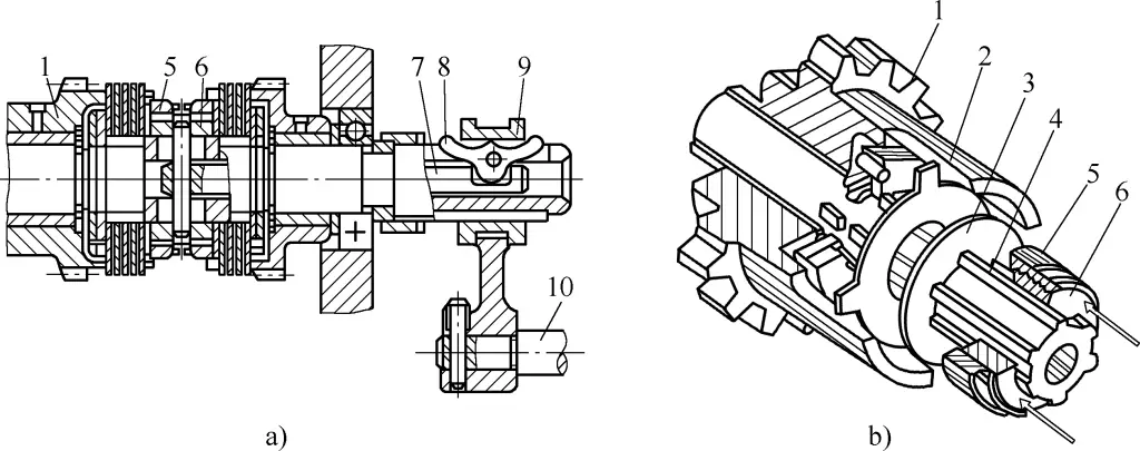
a) Structural diagram
b) Principle diagram
1 – Gear
2 – Outer friction plate
3 – Inner friction plate
4 – Shaft
5 – Pressure sleeve
6 – Threaded ring
7 – Rod
8 – Rocker arm
9 – Sliding ring
10 – Operating device
This clutch consists of several alternating inner and outer friction plates of different shapes. It transmits motion and torque through the friction force generated between the contact surfaces of the friction plates when pressed together. The inner friction plates 3 with splined holes are connected to the splines on the shaft 4; the outer friction plates 2 have smooth circular holes and are loosely fitted on the external circular surface of the shaft’s spline.
The outer circumference of these friction plates has four protruding teeth that fit into the notches in the sleeve part at the right end of the loose gear 1. When not pressed together, the inner and outer friction plates are not in contact, and the spindle remains stationary.
When the operating device 10 (see Figure 3a) moves the sliding ring 9 to the right, the rocker arm 8 on the rod 7 (inside the splined shaft hole) pivots around its fulcrum, causing its lower end to push the rod to the left. The rod has a fixed pin on its left end, which presses the threaded ring 6 and pressure sleeve 5 to the left, compressing the left set of friction plates. Through the friction between the plates, torque is transmitted from the shaft to the loose gear, causing the spindle to rotate forward.
Similarly, when the operating device moves the sliding ring to the left, it compresses the right set of friction plates, causing the spindle to rotate in reverse. When the sliding ring is in the middle position, both left and right sets of friction plates are relaxed, and the motion of shaft 4 cannot be transmitted to the gear, stopping the spindle’s rotation.
The clearance in the plate friction clutch should be appropriate, neither too large nor too small. If the clearance is too large, it will reduce friction force, affecting the normal power transmission of the lathe and causing excessive wear on the friction plates. If the clearance is too small, it may cause overheating during high-speed cutting, leading to “stalling” and damaging the machine. The adjustment of the clearance is shown in Figure 3b and Figure 4.
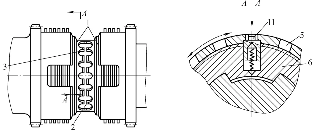
1 – Pressure sleeve
2 – Threaded ring
3 – Spring pin
To adjust, first disconnect the lathe’s power supply and open the headstock cover. Use a tool to press down the spring pin 3 from the notch in the pressure sleeve 1, then rotate the pressure sleeve to make a small axial movement relative to the threaded ring 2. This changes the clearance between the friction plates, thereby adjusting the clamping force between the friction plates and the magnitude of the transmitted torque.
After the clearance is properly adjusted, allow the spring pin to pop out from any notch in the pressure sleeve to prevent the pressure sleeve from loosening during rotation.
3. Overrunning Clutch
Overrunning clutches are mainly used on shafts that alternate between fast and slow speeds to achieve automatic motion conversion. The CA6140 lathe’s carriage contains an overrunning clutch, and its structural principle is shown in Figure 5.

1, 2, 5, 6 – Gear pairs
3 – Roller
4 – Star-shaped body
7 – Spring pin
m – Sleeve
D – High-speed motor
It consists of a star-shaped body 4, three rollers 3, three spring pins 7, and a sleeve m on the right end of gear 2. Gear 2 is loosely mounted on shaft II, while the star-shaped body 4 is connected to shaft II with a key.
When slow motion is transmitted from shaft I through gear pair 1 and 2, sleeve m rotates counterclockwise, driving the rollers 3 towards the narrower part of the wedge gap by friction force. The rollers wedge between the star-shaped body 4 and sleeve m, causing the star-shaped body and shaft II to rotate together.
If the high-speed motor M is started at this time, the fast motion is transmitted to shaft II through gear pairs 6 and 5, driving the star-shaped body to rotate counterclockwise.
As the rotational speed of the star-shaped body exceeds that of the gear sleeve by many times, the rollers compress the springs and exit the wedge gaps, automatically disconnecting the motion between the sleeve and the star-shaped body. Once the high-speed motor stops rotating, the overrunning clutch automatically re-engages, and the gear sleeve once again drives the star-shaped body for slow rotation.
III. Braking Device
The function of the braking device is to overcome the rotational inertia of the moving parts in the headstock during the lathe’s stopping process, quickly stopping the spindle’s rotation to reduce auxiliary time.
Figure 6 shows the band brake installed on shaft IV of the CA6140 lathe headstock. It consists of a brake wheel 8, a brake band 7, and a lever 4. The brake wheel is a steel disc connected to shaft IV by splines. The brake band is a steel band with a layer of steel wire asbestos fixed to its inner side to increase the friction coefficient of the friction surface.
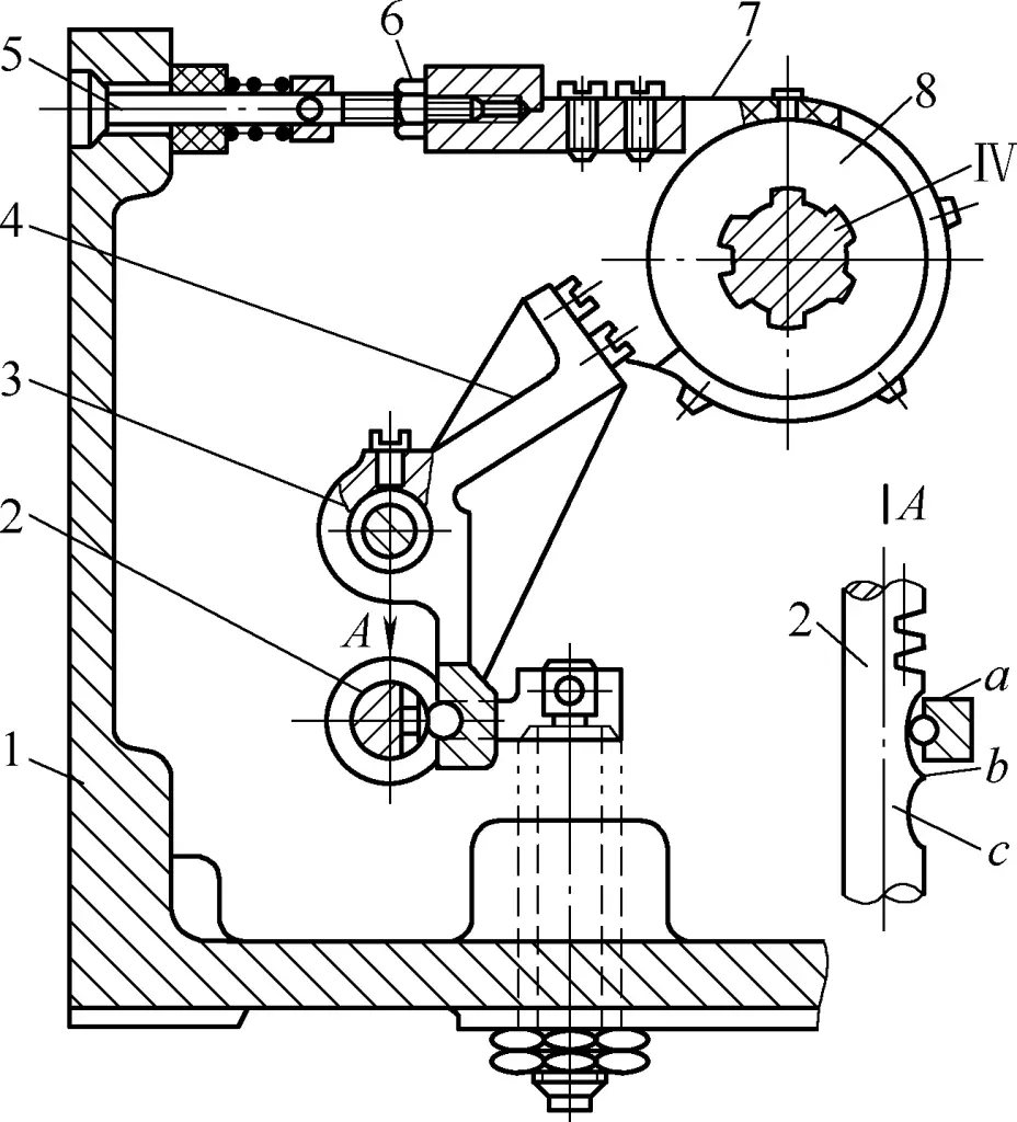
1 – Headstock
2 – Rack
3 – Shaft
4 – Lever
5 – Screw
6 – Nut
7 – Brake band
8 – Brake wheel
The brake band wraps around the brake wheel, with one end connected to the headstock 1 through an adjusting screw 5, and the other end fixed to the upper end of the lever. The lever can pivot around shaft 3.
The brake is linked with the multi-plate friction clutch through rack 2 (i.e., operating device 10 in Figure 3). When its lower end contacts the arc-shaped concave parts a or c on the rack, the spindle is in a rotating state, and the brake band is loose. If the rack shaft is moved to make its protruding part b contact the lower end of the lever, the lever pivots counterclockwise around shaft 3, tightening the brake band around the brake wheel. This produces a friction braking torque, quickly stopping the rotation of shaft IV and the spindle.
The tightness of the brake band in the braking device can be adjusted as follows: Open the main spindle box cover, loosen nut 6, then adjust screw 5 at the back of the spindle box to set the appropriate tightness of the brake band. The standard should be that when stopping, the main shaft can stop quickly within 2-3 revolutions, while the brake band can fully release when starting. After adjustment, tighten the nut and replace the spindle box cover.
IV. Feed Overload Protection Mechanism
The function of the feed overload protection mechanism is to automatically disconnect the power transmission line and stop the tool carriage feed when the feed resistance is too large or when the tool carriage is obstructed due to accidental events during the power feed process, thus avoiding damage to transmission components.
1. Structural Principle
The feed overload protection mechanism of the CA6140 lathe, also known as a safety clutch, is installed in the apron. Its structure is shown in Figure 7, where M 7 is the safety clutch.
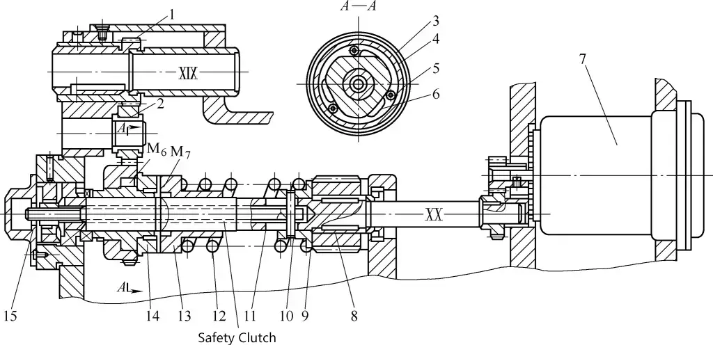
1, 2, 4 – Gears
3 – Star wheel
5 – Roller
6, 12 – Springs
7 – Rapid feed motor
8 – Worm gear
9 – Spring seat
10 – Cross pin
11 – Pull rod
13 – Right half of the clutch
14 – Left half of the clutch
15 – Nut
It consists of left and right halves 14 and 13 with spiral teeth on the end face. The left half is keyed to the star wheel 3 of the overrunning clutch M 6 and is loosely fitted on shaft XX; the right half is spline-connected to shaft XX.
Under normal turning conditions, the left and right halves of the safety clutch mesh with each other under the pressure of spring 3 (see Figure 8a), transmitting the motion from the feed rod to the worm gear 8 (see Figure 7).
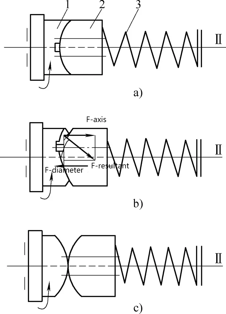
a) Normal transmission
b) Clutch during overload
c) Transmission disconnected
1 – Left half of the clutch
2 – Right half of the clutch
3 – Spring
When overloaded, the axial force acting on the clutch exceeds the pressure of spring 3, pushing the right half of the clutch 2 to the right (see Figure 8b). Although the left half of the clutch 1 rotates normally driven by the feed rod, the right half cannot be driven, so the teeth on both end faces slip (see Figure 8c), breaking the motion connection between shaft XX and the tool carriage, thus protecting the mechanism from damage.
After the overload fault is eliminated, under the pressure of spring 3, the safety clutch returns to the normal working state shown in Figure 8a.
2. Adjustment Method
The maximum allowable feed resistance of the machine determines the pressure set by spring 12 (see Figure 7). To adjust, open the left cover of the apron, use nut 15 to adjust the axial position of the spring seat 9 through pull rod 11 and cross pin 10, which adjusts the magnitude of the spring pressure.
After adjustment, if the feed motion does not stop immediately when overloaded, immediately check the cause and adjust the spring pressure to the appropriate tightness. Replace the spring if necessary.
V. Reversing Mechanism
The reversing mechanism is used to change the direction of motion of the machine’s moving parts, such as the rotation direction of the main spindle, the feed direction of the carriage and cross slide, etc. The CA6140 lathe has the following types of reversing mechanisms.
1. Sliding Gear Reversing Mechanism
Figure 9a shows a sliding gear reversing mechanism. When the sliding gear Z 2 is in the position shown, the motion is transmitted from Z 3 through the intermediate gear Z 0 to Z 2 , and shaft II rotates in the same direction as shaft I; when Z 2 moves to the left to the dotted line position, it directly meshes with Z 1 on shaft I, and shaft II rotates in the opposite direction to shaft I.
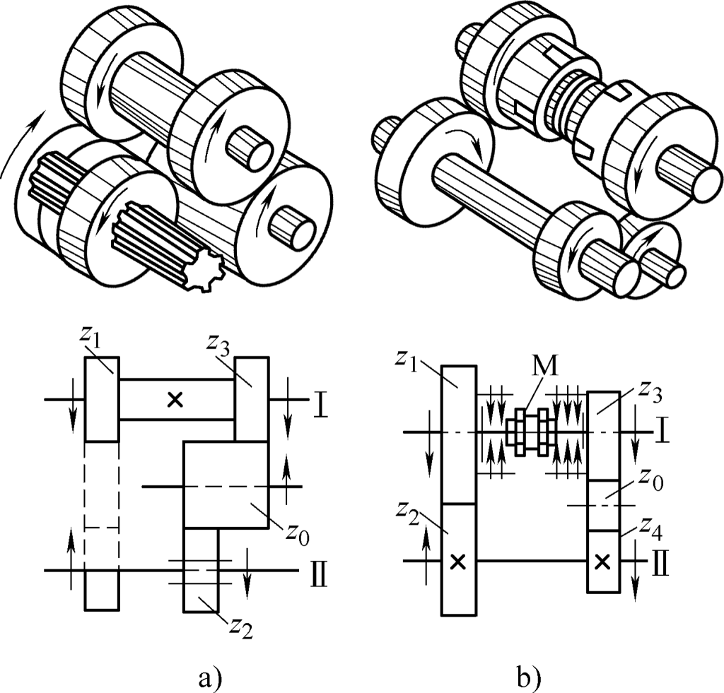
a) Sliding gear reversing mechanism
b) Reversing mechanism composed of cylindrical gears and friction clutch
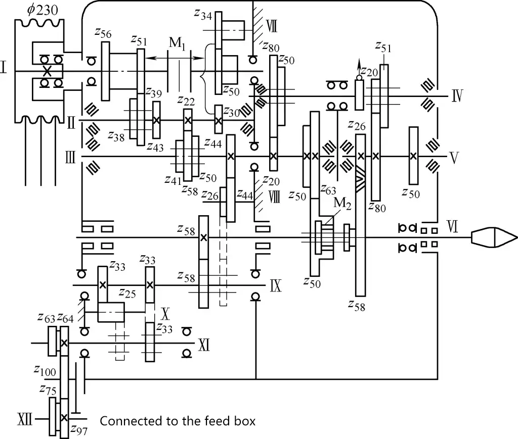
As shown in Figure 10, the gears Z33 , Z25 , Z33 on shafts XI, X, XI in the headstock form a sliding gear reversing mechanism to change the rotation direction of the lead screw, enabling left and right-hand thread cutting.
2. Reversing Mechanism Composed of Cylindrical Gears and Friction Clutch
Figure 9b shows a reversing mechanism composed of cylindrical gears and a friction clutch. When clutch M engages to the left, shaft II rotates in the opposite direction to shaft I; when clutch M engages to the right, shaft II rotates in the same direction as shaft I, such as the reversing mechanism formed by M1 and Z51 Z43 , Z34 Z50 Z30 on shafts I, II, VII in the headstock (see Figure 10).
VI. Control Mechanism
The function of the lathe control mechanism is to change the engagement position of clutches and sliding gears to achieve starting, stopping, speed changing, and direction changing of the main motion and feed motion.
To facilitate operation, in addition to some simple fork controls, a centralized control method is often used, where one handle controls several transmission components (such as sliding gears, clutches, etc.), thus reducing the number of handles and making operation easier.
1. Main Spindle Speed Control Mechanism
Figure 11 shows the spindle speed control mechanism of the CA6140 lathe. There are two sets of gears A and B inside the headstock. The double-linked gear A has two meshing positions, left and right; the triple-linked gear B has three meshing positions, left, middle, and right. The two sets of sliding gears can be controlled by the handle 6 installed on the front side of the headstock.
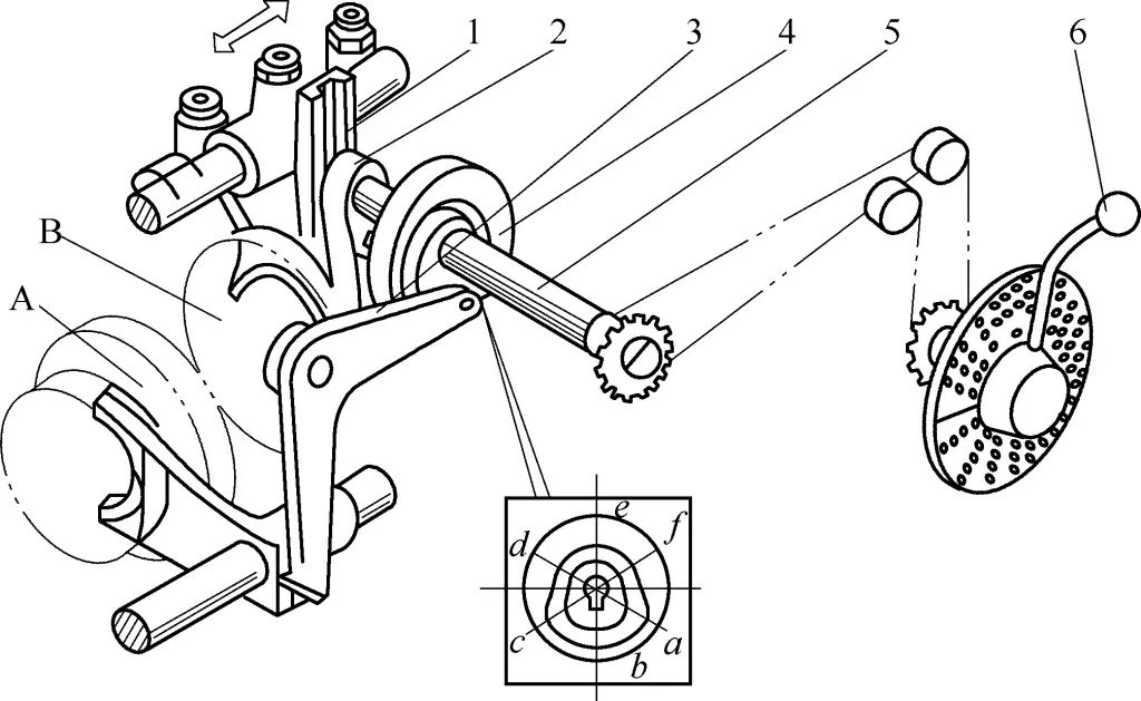
1—Shift fork
2—Crank
3—Lever
4—Cam
5—Shaft
6—Handle
The handle rotates shaft 5 through a chain drive, with a disc cam 4 and crank 2 fixed on the shaft. There is a closed curved groove on the cam (marked by six positions a to f in Figure 11), where positions a, b, and c have a larger radius, while positions d, e, and f have a smaller radius. The cam groove controls the double-linked gear A through lever 3.
When the roller of the lever is at the large radius part of the cam curve, gear A is in the left position; when it’s at the small radius part, it’s moved to the right position. The circular pin and roller on the crank are installed in the long slot of the shift fork 1. When the crank rotates with the shaft, it can shift the sliding gear B, placing gear B in three different positions: left, middle, and right.
Through the rotation of the handle and the coordinated actions of the crank and lever, six different combinations of axial positions for gears A and B can be achieved, resulting in six different speeds. Therefore, it’s also called a single-handle six-speed control mechanism.
2. Longitudinal and transverse power feed control mechanism
Figure 12 shows the longitudinal and transverse feed control mechanism of the CA6140 lathe. It uses a single handle to centrally control the engagement, disengagement, and direction reversal of longitudinal and transverse power feed movements. The handle’s movement direction is consistent with the tool carriage movement direction, making it very convenient to use.
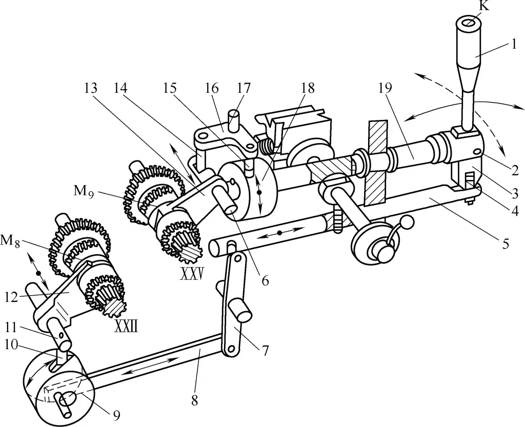
1—Handle
2, 17—Pin shafts
3—Handle seat
4—Ball-head pin
5, 6, 11, 19—Shafts
7, 16—Levers
8—Connecting rod
9, 18—Cams
10, 14, 15—Pins
12, 13—Shift forks
When the handle 1 is moved left or right, causing the handle seat 3 to swing around the pin shaft 2 (the pin shaft is mounted on the axially fixed shaft 19), the open slot at the bottom of the handle seat moves shaft 5 axially through the ball-head pin 4, which then rotates the cylindrical cam 9 through lever 7 and connecting rod 8.
Then the curved groove on the cylindrical cam moves the shaft 11 and the shift fork 12 fixed on it forward or backward through pin 10, causing the shift fork to move the clutch M 8 , engaging it with one of the two idle gears on shaft ⅩⅫ. This engages the longitudinal power feed movement, and the tool carriage correspondingly moves left or right for longitudinal feed.
If the handle is moved forward or backward, causing shaft 19 and the cylindrical cam 18 fixed on its left end to rotate through the handle seat, the curved groove on the cam makes lever 16 swing around pin shaft 17 through pin 15.
Then, through another pin 14 on the lever, it moves shaft 6 and the shift fork 13 fixed on it forward or backward, causing the shift fork to move the clutch M 9 , engaging it with one of the two idle gears on shaft XXV. This engages the transverse power feed movement, and the tool carriage correspondingly moves forward or backward for transverse feed.
When the handle is in the middle upright position, both clutches M 8 and M 9 are in the middle position, and the power feed transmission chain is disengaged. When the handle is moved to any left, right, forward, or backward position, if the button K on top of the handle is pressed, the rapid traverse motor starts, and the tool carriage moves quickly in the corresponding direction.
VII. Split Nut Mechanism
The function of the split nut mechanism is to engage or disengage the motion from the lead screw. When cutting threads or worms, the split nut is engaged, and the lead screw drives the carriage and tool post through the split nut.
The structure of the split nut mechanism is shown in Figure 13. The upper and lower half nuts 1 and 2 are installed in the dovetail guide on the back wall of the carriage and can move up and down. There is a cylindrical pin 3 installed on the back of each half nut, with its protruding end inserted into two curved slots in the slotted disc 4.
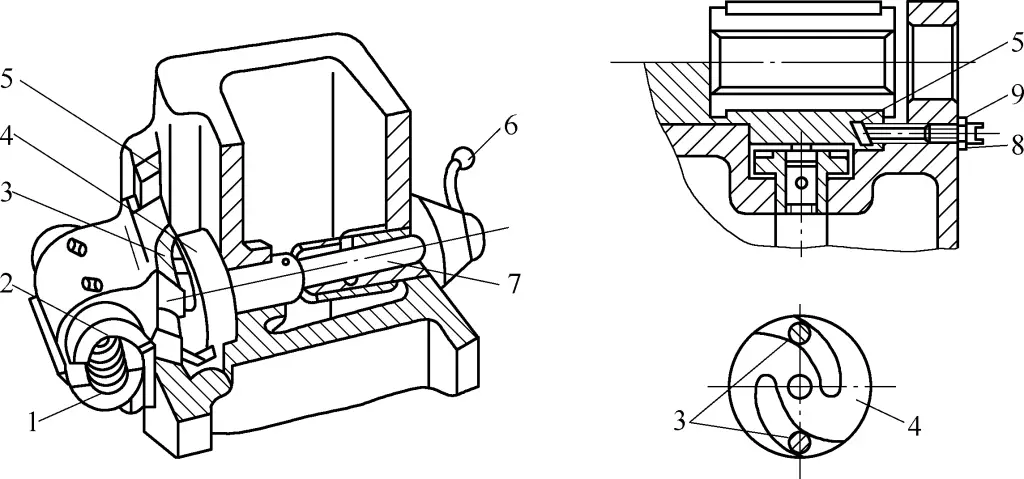
1, 2—Half nuts
3—Cylindrical pin
4—Slotted disc
5—Inlay strip
6—Handle
7—Shaft
8—Screw
9—Nut
When the handle 6 is moved to the right, causing the slotted disc to rotate counterclockwise through shaft 7, the curved slots force the two cylindrical pins to move closer together, bringing the upper and lower half nuts together to engage with the lead screw. The tool post then feeds through the carriage driven by the lead screw nut. When the slotted disc rotates clockwise, the curved slots cause the two half nuts to separate through the cylindrical pins, disengaging the two half nuts from the lead screw, and the tool post stops feeding.
The split nut and inlay strip must fit properly, otherwise it will affect the accuracy of thread cutting, and may even cause the split nut control handle to automatically jump position, resulting in uneven pitch, chaotic threads, or axial movement of the split nut shaft.
The clearance between the split nut and the dovetail guide (generally should be less than 0.03mm) can be adjusted by tightening or loosening the inlay strip 5 with screw 8, and then locked with nut 9 after adjustment.
VIII. Interlock Mechanism
During lathe operation, if due to operational error, both the lead screw drive and the longitudinal/transverse power feed (or rapid traverse) are engaged simultaneously, it will damage the lathe. To prevent such accidents, there is an interlock mechanism in the carriage to ensure that when the split nut is engaged, the power feed cannot be engaged; conversely, when the power feed is engaged, the split nut cannot be engaged.
The working principle of the interlock mechanism for the CA6140 lathe is shown in Figure 14 (also refer to Figure 12). On the split nut control handle 1 (shaft 7 in Figure 13), there is a shoulder T, with a fixed sleeve 3, a ball-head pin 4, and a spring 5 installed in the longitudinal power feed control shaft 6.
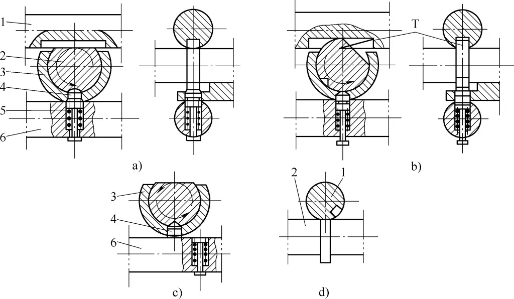
1, 2, 6—Shafts
3—Fixed sleeve
4—Ball-head pin
5—Spring
Figure 14a shows the situation when both power feed and lead screw drive are disengaged. When engaging the split nut, as shaft 2 rotates through an angle (see Figure 14b), its shoulder T fits into the slot of the transverse power feed control shaft 1 (shaft 19 in Figure 12), locking it and preventing it from rotating, thus preventing the engagement of transverse power feed.
At the same time, shoulder T pushes the ball-head pin 4 in the horizontal hole of the fixed sleeve 3 downward, inserting its lower end into the hole of shaft 6 (shaft 5 in Figure 12), locking the shaft and preventing it from engaging the transverse power feed.
When the longitudinal power feed is engaged (shown in Figure 14c), as the shaft moves axially, its hole no longer aligns with the ball-head pin, preventing the ball-head pin from moving downward. This prevents the split nut handle shaft from rotating, thus preventing the split nut from engaging.
When the transverse power feed is engaged (shown in Figure 14d), as the shaft rotates through a certain angle, its groove no longer aligns with the shoulder T on the shaft, preventing the shaft from rotating, thus preventing the split nut from engaging.
IX. Adjustment of Clearance between Cross Slide Lead Screw and Nut
The structure of the cross slide lead screw is shown in Figure 15, consisting of a front nut 1 and a rear nut 6, fixed to the top of the cross slide 5 by screws 2 and 4 respectively, with a wedge block 8 in between.
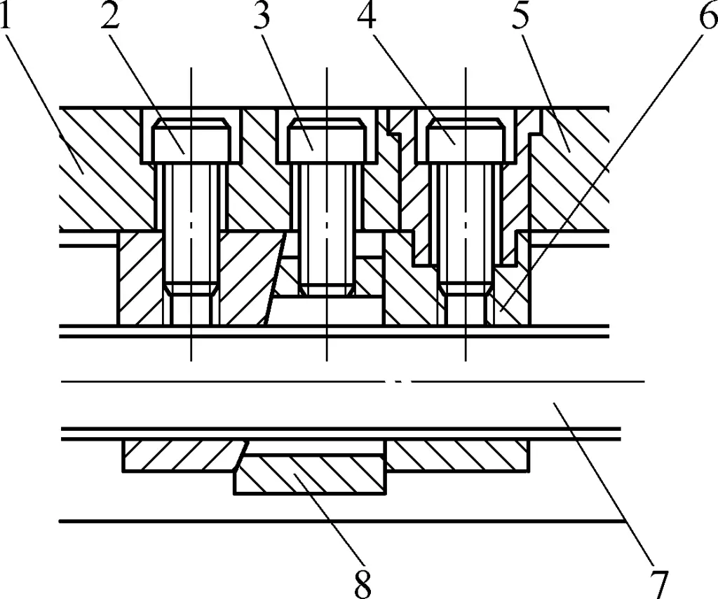
1—Front nut
2~4—Screws
5—Cross slide
6—Rear nut
7—Lead screw
8—Wedge block
When the clearance between the lead screw 7 and the nut threads becomes too large due to wear, loosen the fixing screws on the front nut, tighten screw 3, and pull the wedge block upward. The wedge action pushes the nut to the left, reducing the clearance between the lead screw and the nut threads.
After adjustment, the cross slide lead screw handle should rotate smoothly, with backlash less than 1/20 of a turn in both forward and reverse directions. After proper adjustment, tighten screw 2.

