Hot vs Cold Extrusion: Key Differences and Applications
When it comes to shaping materials into precise forms, extrusion stands out as one of the most versatile manufacturing processes.…
Cold extrusion leverages the principle of plastic deformation of metal materials. Under room temperature conditions, the cold state metal blank is placed into the mold cavity installed on the press.
Under significant pressure and a certain speed, the metal blank is forced to undergo plastic flow. Through the gap between the punch and die, or the die exit, hollow parts are extruded or solid parts with a cross-section smaller than the blank’s cross-section.
This process can achieve the desired shape and size while also maintaining high mechanical properties of the extruded parts. Cold extrusion is one of the non-chip or minimal chip part processing techniques and is an advanced method in metal plastic processing.
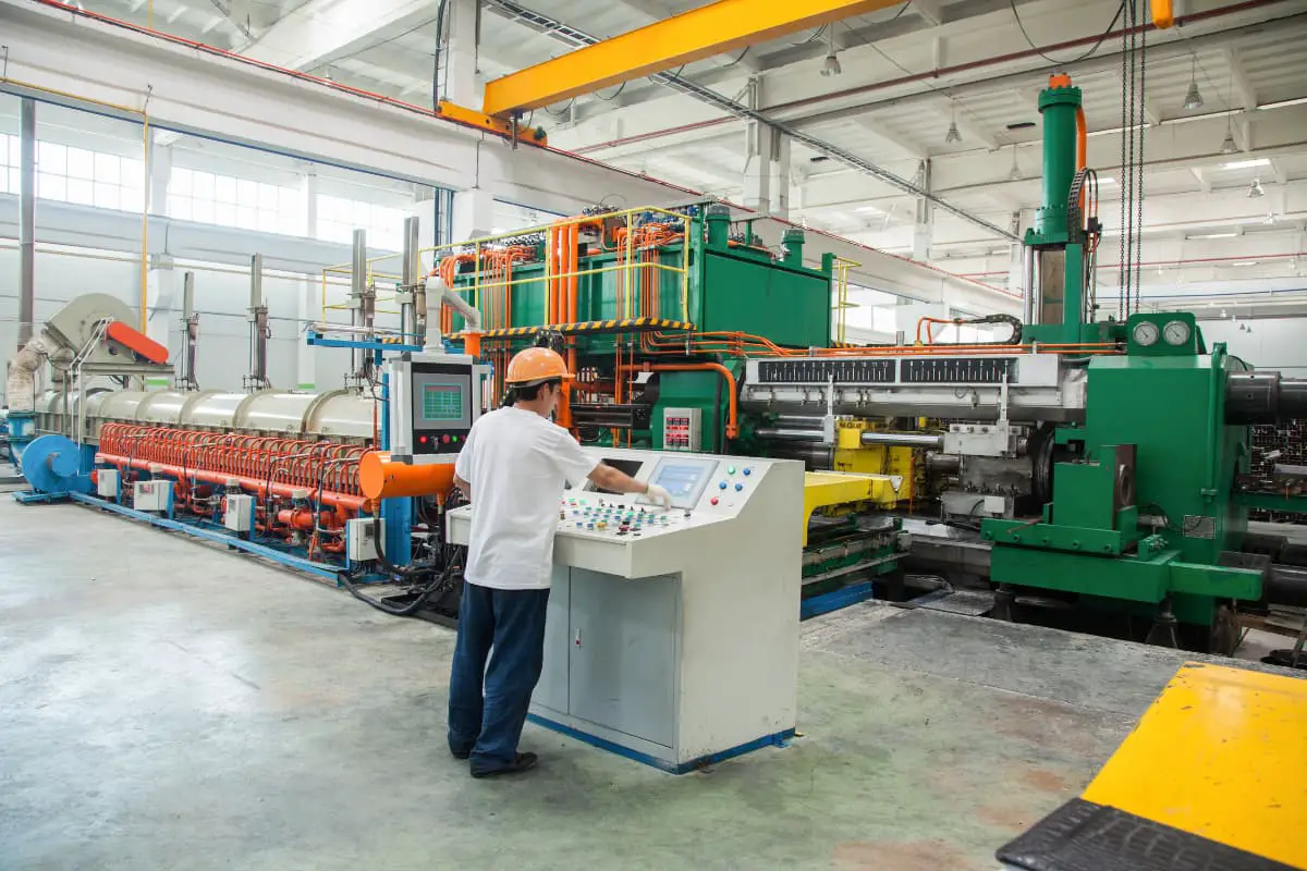
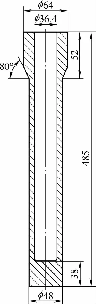
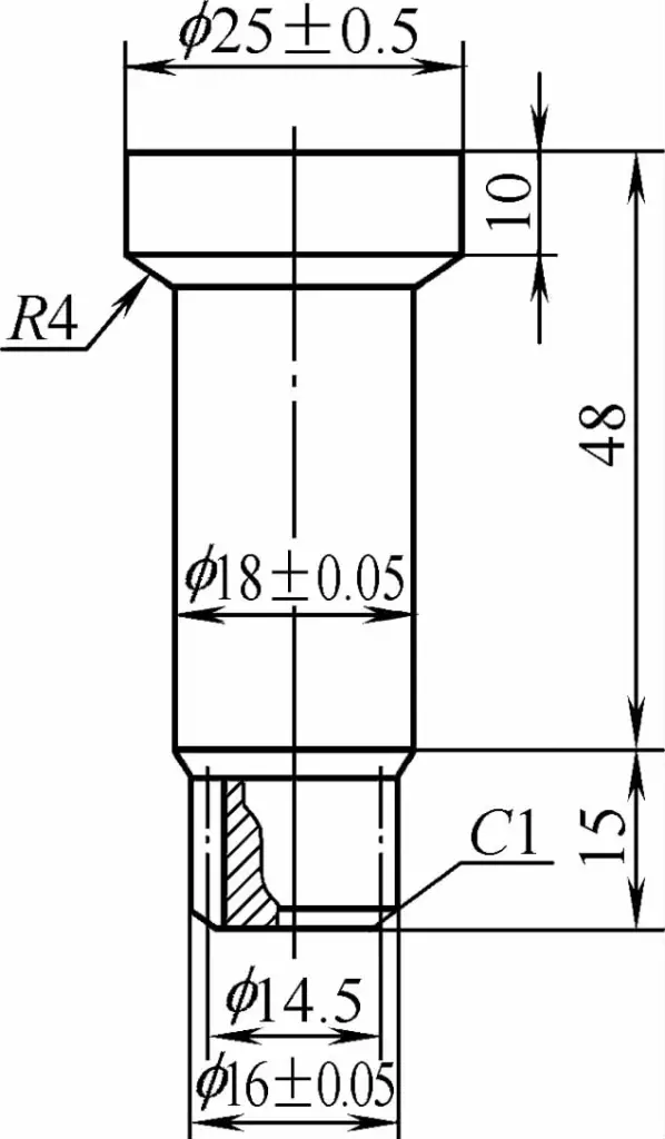
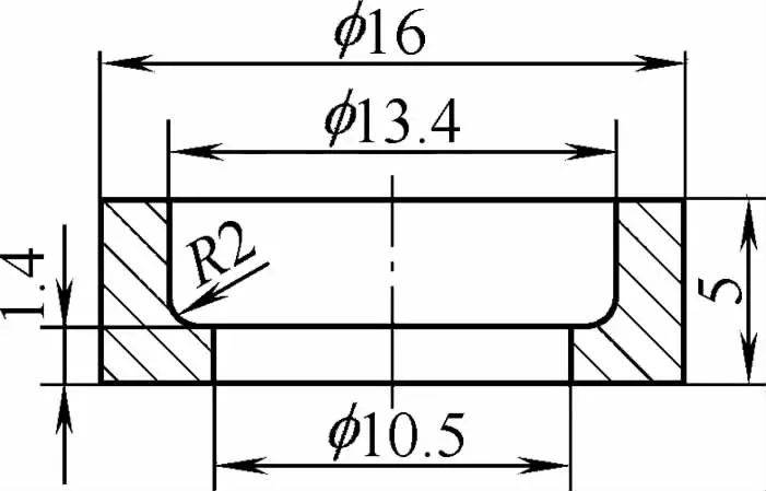
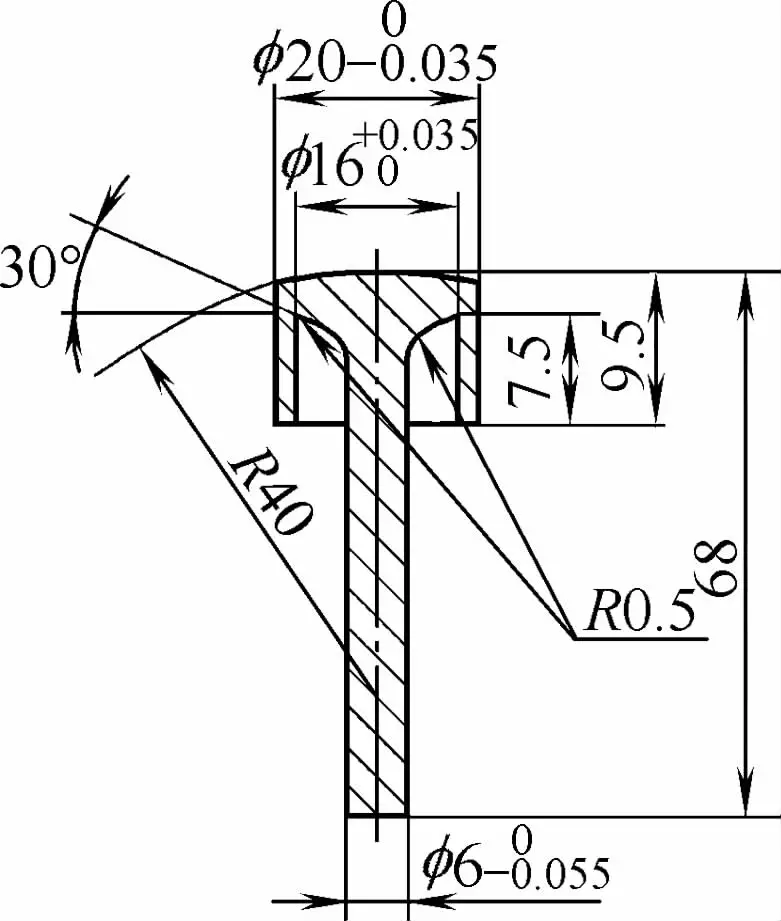
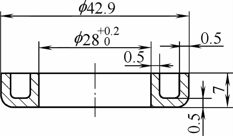
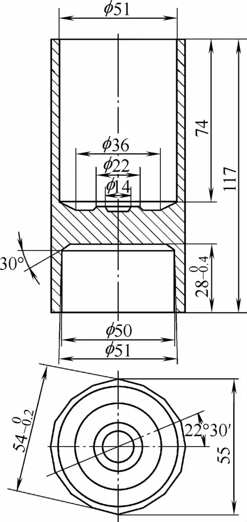
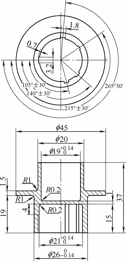
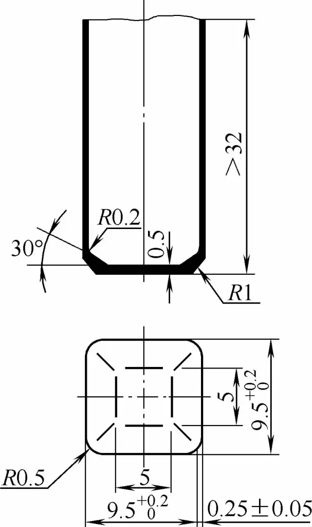
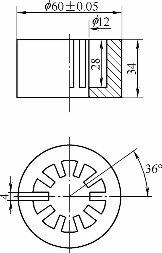
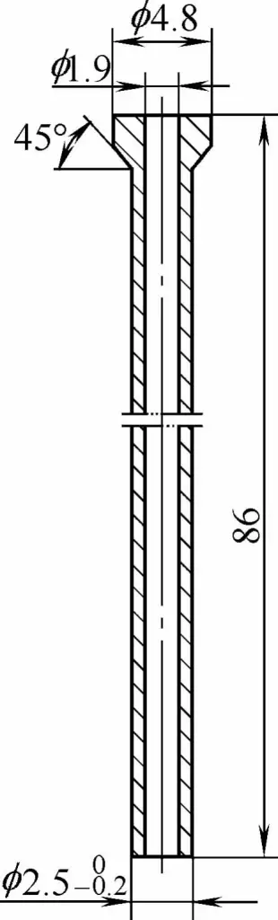
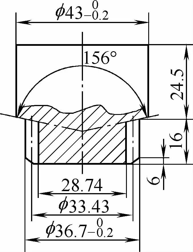
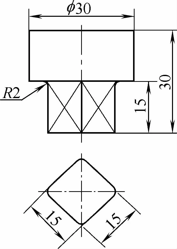
The common carbon steel sewing machine shuttle core, low carbon steel deep-hole cylinder, medium carbon steel washing machine gear shaft, and carbon tool steel connecting cap shown in Figures 1-1 to 1-4 are all produced by cold extrusion.
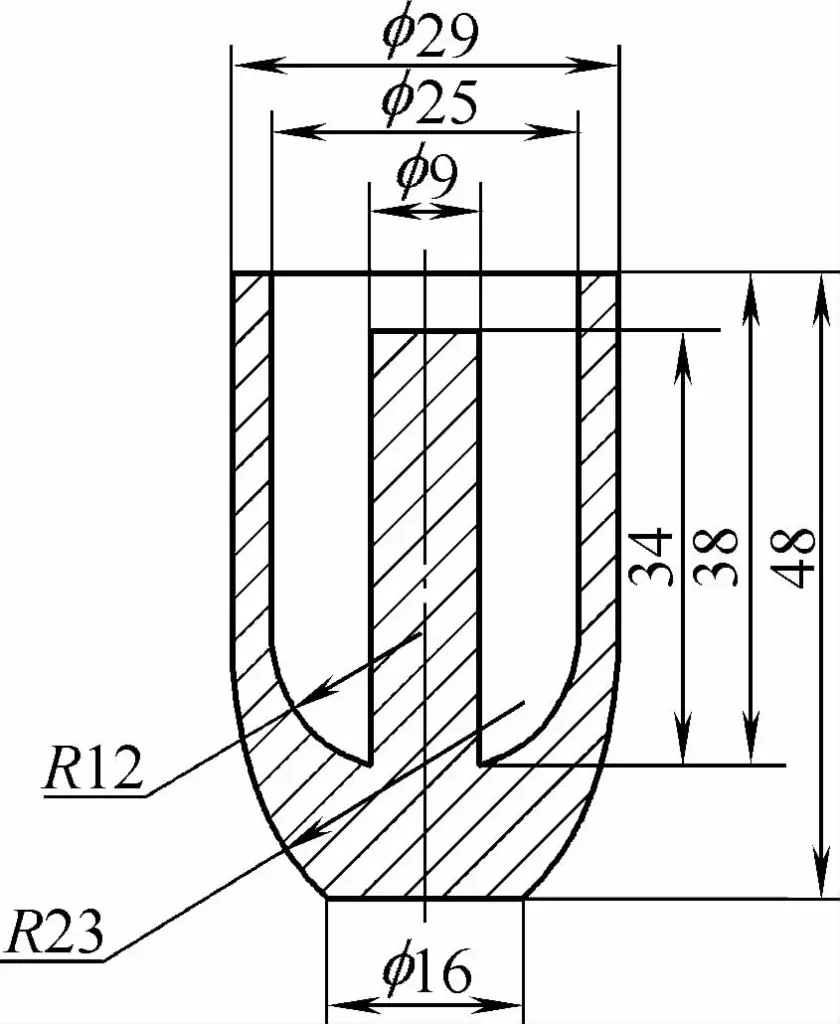
As can be seen from the product images above, cold extrusion relies on the mold to control metal flow and relies on a substantial volume transfer of softened metal to form the required parts. Therefore, the success or failure of the cold extrusion process is closely related to the mold structure design, mold materials, and the annealing treatment of the metal blank.
Cold extrusion can be used for the production of batch metal parts and also for processing various mold cavities. Figures 1-5 to 1-13 show cold extruded parts of pure aluminum, rust-proof aluminum, hard aluminum, forged aluminum, pure copper, oxygen-free copper, brass, chrome molybdenum steel, and bearing steel.
The forming speed range in cold extrusion processing is wide. The equipment used can operate on specialized cold extrusion presses, general mechanical presses or hydraulic machines, friction presses, or high-speed hammers.
Cold extrusion can be classified according to the direction of metal flow, the speed of metal flow, etc.
Based on the relationship between the direction of metal flow and the movement direction of the punch, there are seven types of cold extrusion methods.
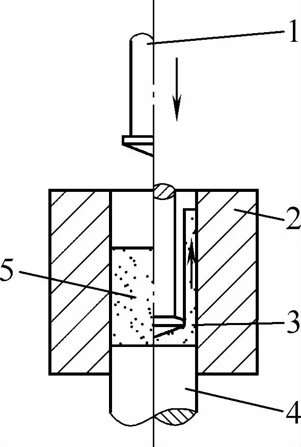
In forward extrusion, the direction of metal flow is the same as the direction of the punch movement. Fig 1-14 shows the case of forward extrusion of a solid workpiece.
During processing, the blank is first placed in the die, and there is a hole at the bottom of the die that is approximately the same size as the outer diameter of the part to be made. Then, the punch is used to apply pressure and extrude the blank.
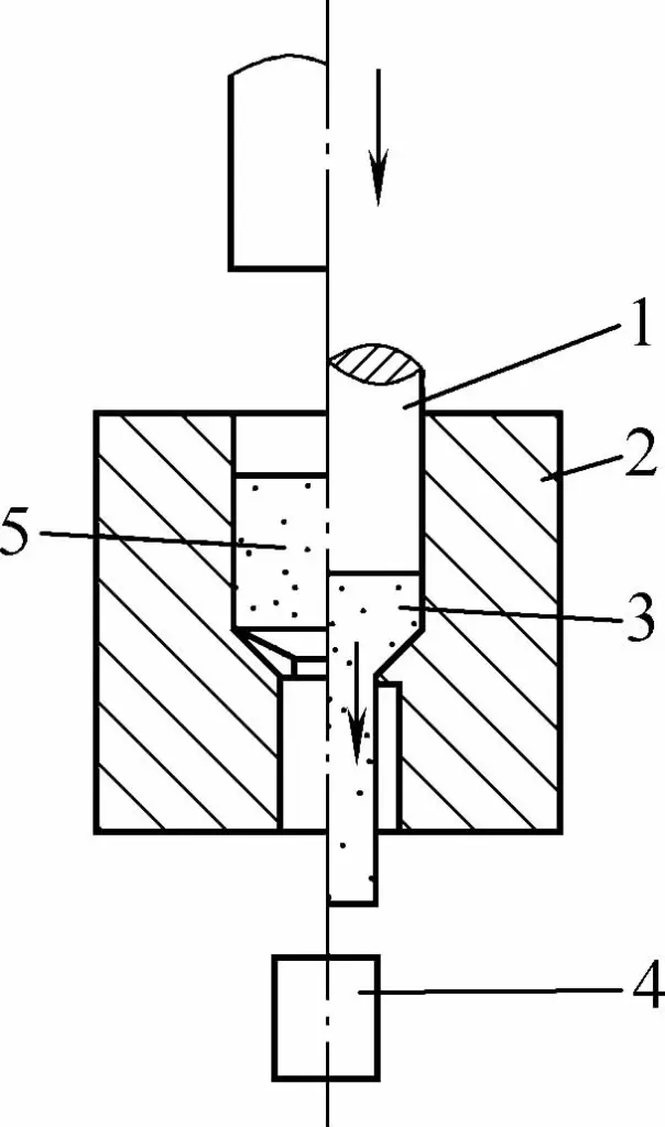
1 -Punch
2- Die
3 -Extruded Part
4- Ram
5- Billet
The pressure of the punch causes the metal to enter a plastic state and forces the metal to flow out from the small hole in the die, thereby forming the required workpiece.
Generally speaking, forward extrusion can produce solid parts of various shapes (using solid blanks), and it can also produce hollow parts of various shapes (using hollow blanks or cup-shaped blanks).
Fig 1-15 shows the case of forward extrusion of a hollow workpiece. Hollow workpieces include casings, shell casings, and liners, etc.
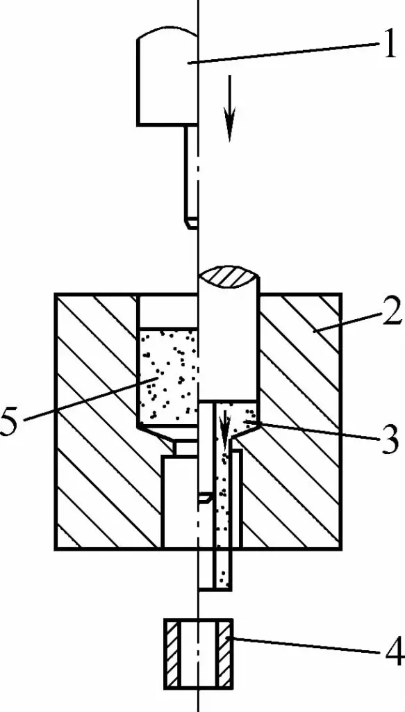
1 -Punch
2- Die
3- Extruded Part
4- Ram
5- Billet
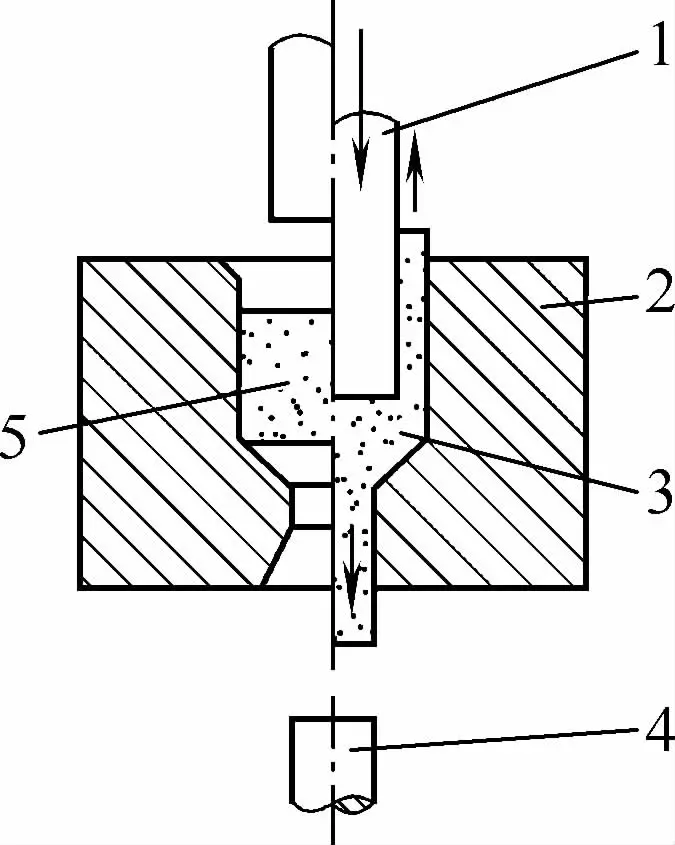
In indirect extrusion, the direction of metal flow is opposite to the movement of the punch. Figure 1-16 illustrates the process of indirectly extruding a hollow cup-shaped part. During the operation, a flat billet is placed on the bottom of the die (the radial gap between the die and punch equals the wall thickness of the cup-shaped part).
1- Punch
2- Die
3 -Extruded Part
4 -Ram
5 -Billet
When the punch applies pressure to the billet, the metal flows upwards through the gap between the punch and die, thereby forming the desired hollow cup-shaped part. Indirect extrusion can produce various cross-sectional hollow cup-shaped parts, such as covers, casings, sleeves, pipes, shields, and lamp bases.
During combined extrusion, some of the billet’s metal flows in the same direction as the punch’s movement, while the rest flows in the opposite direction. Figure 1-17 shows the working condition of combined extrusion.
1- Punch
2 -Die
3 -Extruded Part
4 -Ram
5- Billet
Under the pressure of the punch, the metal flows in two different directions, causing bidirectional extrusion deformation. This is an extrusion method that combines both direct and indirect extrusion.
Based on the different combinations of forward and backward extrusion, compound extrusion can be divided into the following three scenarios: Rod-Rod Compound Extrusion (see Figure 1-18a), which is a combination of backward extrusion rod pieces and forward extrusion rod pieces;
Cup-Cup Compound Extrusion (see Figure 1-18b), which is a combination of backward extrusion cup pieces and forward extrusion cup pieces; Cup-Rod Compound Extrusion (see Figure 1-17), which is a combination of backward extrusion cup pieces and forward extrusion rod pieces.
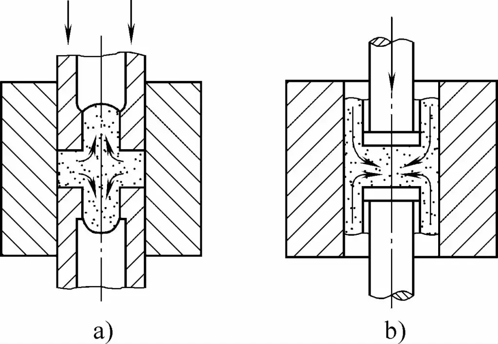
a) Rod-Rod piece
b) Cup-Cup piece
Compound extrusion methods can be used to manufacture double cup parts (such as car piston pins), as well as cup-rod parts (like sewing machine shuttle cores).
This is a form of forward extrusion with a lesser degree of deformation, where the cross-section of the blank is only slightly reduced. Figure 1-19 shows the operation of reducing extrusion.
Reducing extrusion is mainly used to manufacture stepped shaft parts with small diameter differences, and can also be used as a trimming process for deep-hole cup pieces.
Forward extrusion, backward extrusion, compound extrusion, and reducing extrusion are the four most widely used forming methods in cold extrusion. The metal flow direction in these four methods is parallel to the axis of the punch, hence they are collectively referred to as axial cold extrusion.
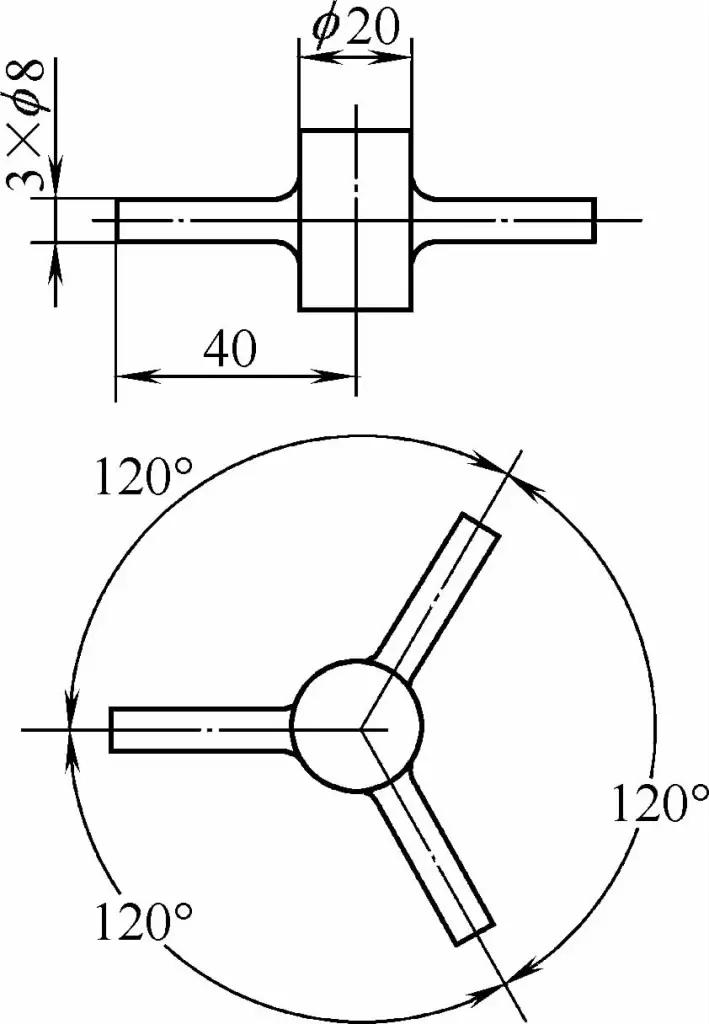
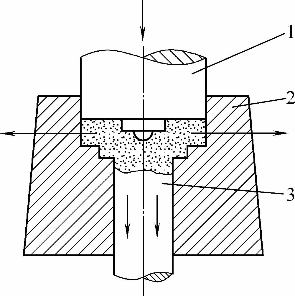
In radial extrusion, the flow direction of the metal is perpendicular to the direction of the punch’s movement. Figure 1-20 shows the operation of radial extrusion. Radial extrusion is further divided into centrifugal extrusion and centripetal extrusion, mainly used for manufacturing gear blanks with shoulder and cross shaft parts.
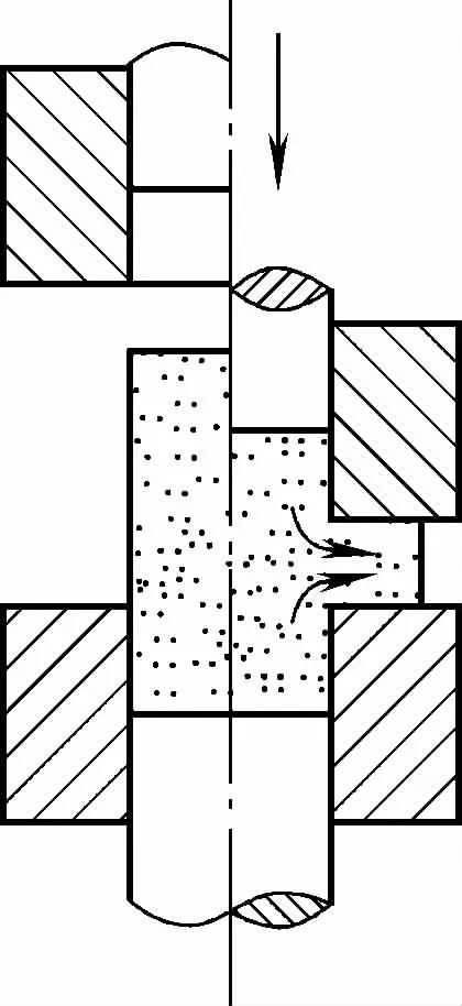
Figure 1-21 illustrates the production of aluminum parts using the radial centrifugal cold extrusion method, where the metal blank flows outward radially under the pressure of the punch.
Figure 1-22 shows an aluminum dial in communication equipment, where the inner teeth and the Arabic numerals on the outer circle are extruded in sequence, with the inner teeth processed using the radial centripetal extrusion method.
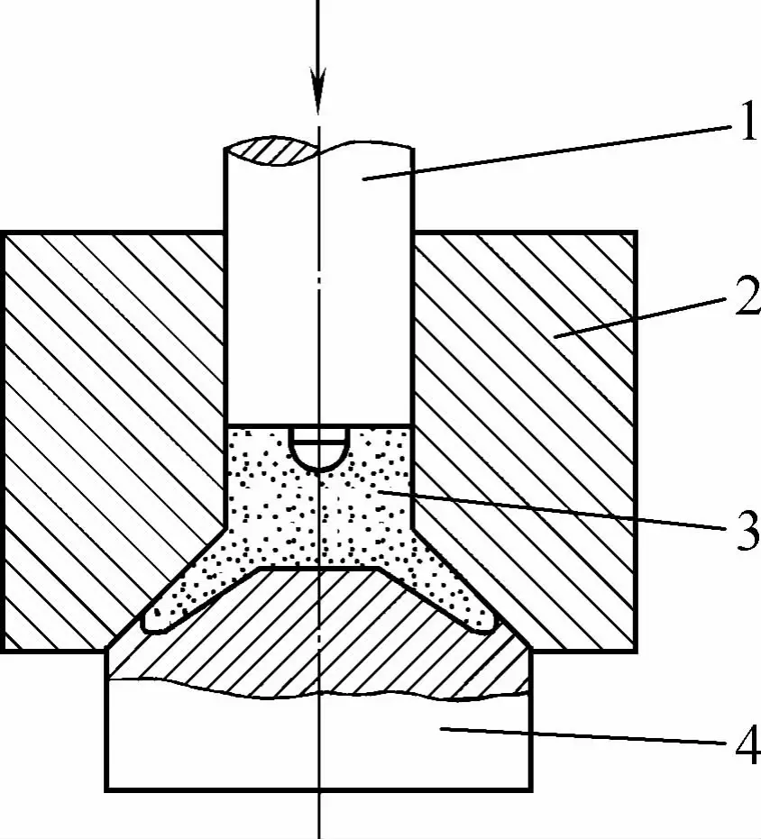
During extrusion, the flow direction of the metal is tilted or bent relative to the motion direction of the punch. Figure 1-23 depicts the working condition of oblique extrusion. Oblique extrusion is primarily used for manufacturing various complex-shaped parts with tilted or bent branches.
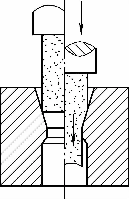
During deformation, the metal flow exhibits characteristics of both extrusion and upsetting, i.e., part of the metal flows axially along the punch, while another part flows radially. This forming method, which combines cold upsetting and cold extrusion, is known as the upset extrusion method. Figure 1-24 illustrates the working condition of the upset extrusion method.
It is primarily used for manufacturing bulged head parts and stepped shaft parts. The supporting rod shown in Figure 1-25 is processed using this upset extrusion method, which first involves regular extrusion followed by upsetting the head, combining cold extrusion and cold upsetting in the same operation.
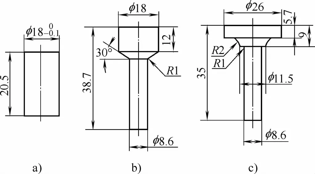
a) Blank
b) Extrusion
c) Upsetting
Cold extrusion can be classified into general-speed extrusion, low-speed extrusion, and high-speed extrusion, depending on the flow speed of the metal blank filling the mold cavity.
Cold extrusion speed ranges between 0.5-2m/s. The equipment includes general presses, toggle presses, friction presses, and special extrusion presses.
The equipment used includes hydraulic presses of various tonnages, with speeds reaching between 0.01-0.1m/s.
The slide speed of the equipment can reach 6-20m/s, such as high-speed hammers, counterblow hammers, and air hammers.