1. File Fitting Process
The operation of using a filing method to make two or more matching parts meet specified technical requirements is called file fitting.
(1) Selection of reference parts for file fitting
1) Definition of reference parts for file fitting
Reference parts for file fitting refer to the “template part” selected through process analysis before file fitting among all filing fitting parts. This part, after processing, can be used as a measurement template, cooperating with measuring tools during the filing adjustment of other matching parts to jointly measure and control the filing precision of other matching parts, thereby accurately and quickly completing the required file fitting accuracy.
2) Principles for selecting reference parts
Reference parts should more easily achieve the required dimensional accuracy, form and position accuracy, and surface roughness values through filing than other matching parts.
Convex parts are preferred as reference parts because compared to concave parts, convex parts are easier to measure, i.e., easier to control their accuracy through measurement. As concave parts have internal surfaces, measuring tools are difficult to enter, making measurement operations challenging. If concave parts are easy to measure, they can also be used as reference parts to file fit with convex parts.
(2) File Fitting Process
1) Filing of reference parts
The file fitting process is generally divided into individual filing and filing adjustment processes. The individual filing method is as previously described. Usually, the file-fitting process is: first, file the reference parts. When the reference parts meet the required dimensional accuracy, form and position accuracy, and surface roughness (the surface roughness of the reference parts is usually one grade higher than the technical requirements on the drawings), the processing ends. In the subsequent file fitting, the reference parts, as template parts, can no longer be processed.
2) Filing of other matching parts
File other matching parts to meet the form and position accuracy and surface roughness requirements while leaving the trimming allowance for file fitting. If a concave part is a matching part, generally, to facilitate controlling processing accuracy when processing the internal surface of a concave part, it is advisable to choose relevant external surfaces of the concave part as measurement references; hence, the outline reference surface of the concave part must achieve higher form and position accuracy.
3) Adjustment Process
Use the reference part to compare and trial fit other matching parts. Measure matching parts using the light gap method or dye smear method to determine the filing areas of matching parts. Then, combine measuring tools to measure matching parts, determine the trimming allowance, and gradually process to achieve the required fitting precision.
(3) About Non-contact Fitting
In non-contact fitting, since it is impossible to use reference parts (measurement templates) to directly measure matching parts, to achieve the required fitting precision, one can only control all fitting parts’ dimensional accuracy and form and position accuracy through meticulous measurement work.
To make the file-fitting work more effective, the impact of form and position errors on the functional dimensions should be comprehensively analyzed, and reference parts should be used as templates for comparative work as much as possible. Through careful observation and accurate measurement, adjustments and trial fitting of matching parts are carried out.
Moreover, to perform satisfactory non-contact fitting, one needs good powers of observation and hand sensitivity during trial fitting. Techniques for using sharp calipers can greatly aid corrections during file fitting. These skills require exploration, summary, and accumulation of experience.
(4) About Measuring and Controlling Symmetry in Filing
After processing, fitting parts require the straightness and flatness of the outline to meet certain precision requirements.
For symmetric fitting parts, rotational fitting is usually required. If symmetry requirements are not met during individual processing, post-fitting outline flatness will find it difficult to meet the required precision, especially after rotation, where outline flatness can’t be assured, as shown in Figure 1. Therefore, processing order should be reasonably arranged, and symmetry controlled through measurement.
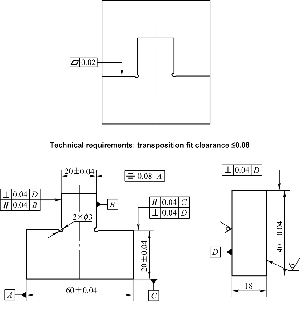
1) Processing Order
As shown in Figure 1, to ensure the symmetry of the boss (dimension 20) with reference A (see Figure 1), processing should retain material on one side (see Figure 2) instead of sawing out all material from both sides of the boss. Control dimension L on filed surface I. When dimension L meets the requirements (as described below), saw off this side’s remaining material and simultaneously control filed surface II to (20±0.04)mm.
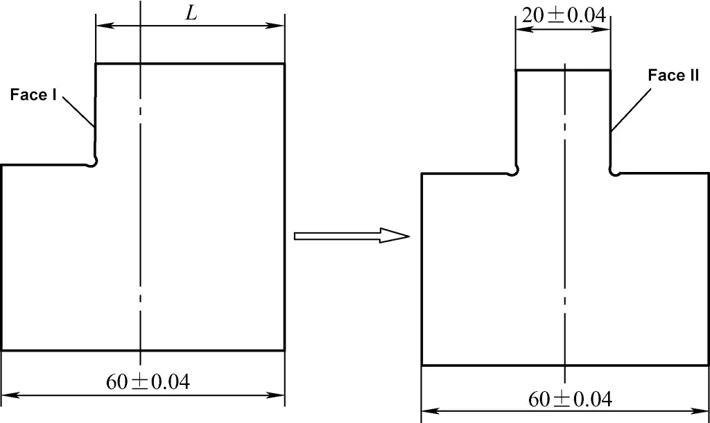
2) Measurement of Symmetry Error
From the perspective of filing processing, symmetry error refers to the deviation between the central plane of the two processed surfaces and the theoretical central plane after filing processing.
As shown in Figure 1, for the workpiece, the symmetry tolerance of the boss (20±0.04) mm relative to the axis datum A is 0.08mm. As shown in Figure 3, to ensure this symmetry requirement, it is necessary to guarantee it through indirect measurement of dimension L.
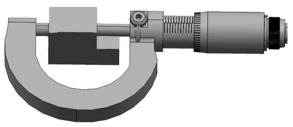
① Maximum control dimension Lmax.
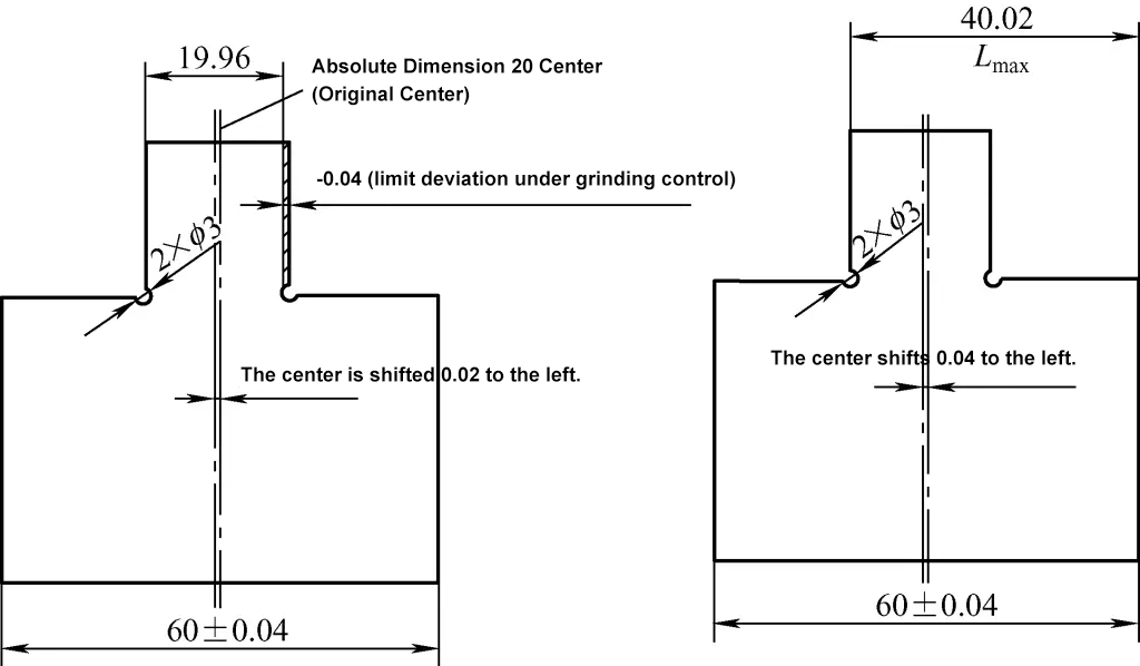
As shown in Figure 4, under the control of boss dimension filing, the lower limit deviation is 19.96mm, resulting in an original center left offset of 0.02mm. The current symmetry tolerance is 0.08mm. According to the concept of symmetry tolerance, the maximum allowable left offset of the boss center plane is (0.02 + 0.02) mm. Hence, the control dimension Lmax = 40.02mm.
② Minimum control dimension Lmin.
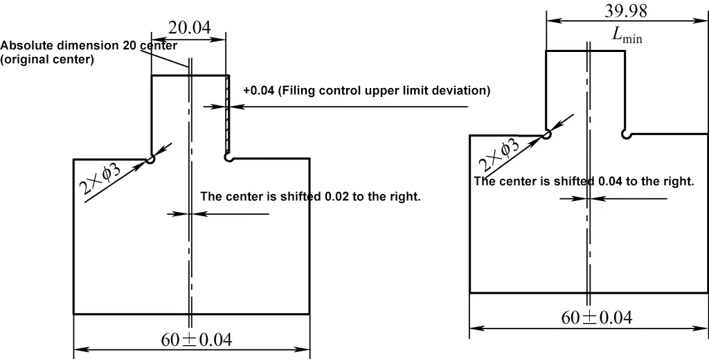
As shown in Figure 5, after filing the boss dimension to the upper limit deviation of 20.04mm, the original center right offset is 0.02mm. The current symmetry tolerance is 0.08mm. According to the concept of symmetry tolerance, the maximum allowable right offset of the boss center plane is (0.02 + 0.02) mm. Hence, the control dimension Lmin = 39.98mm.
2. Example Analysis of Part Filing and Fitting – Part One
As shown in Figures 6a and 6b, it is an instrument for measuring the gap between the stator and rotor during motor maintenance (also called a feeler gauge), with the structure described as follows:
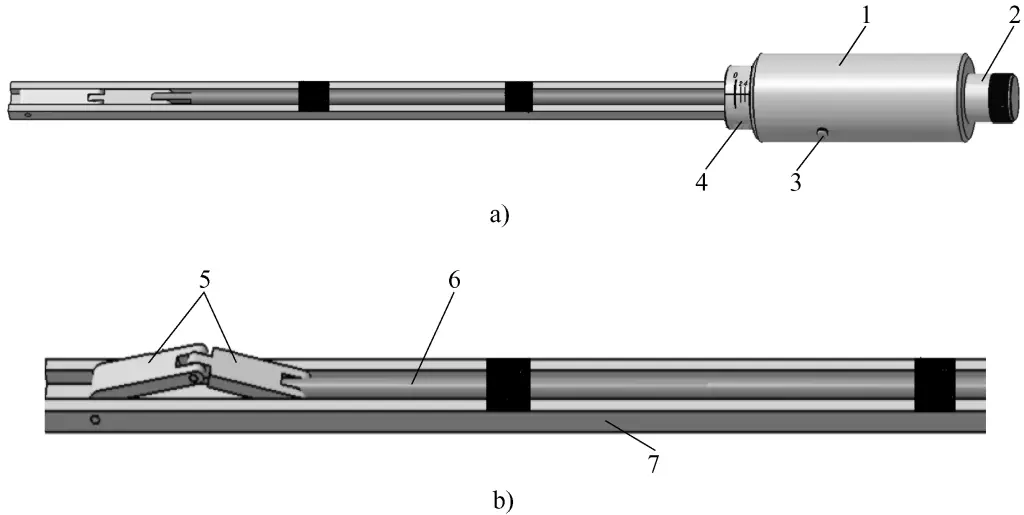
1—Movable Sleeve
2—Fine Adjustment Device
3—Movable Pin Shaft
4—Fixed Sleeve
5—Measuring Block
6—Movable Measuring Rod
7—Ruler Body
1) The movable sleeve and the tail end of the movable measuring rod are connected by threads (thread specification is M10×1mm).
2) The two measuring blocks and the movable measuring rod are connected by movable hinges.
The working principle of the feeler gauge is as follows:
When the movable sleeve is not rotated, the zero mark on the fixed sleeve aligns with the zero line on the movable sleeve (see Figure 6a). When the movable sleeve is turned counterclockwise, the movable pin shaft rotates in a circle along the circular slot of the fixed sleeve. According to the principle of spiral transmission, the movable measuring rod will move to the left (as shown in Figure 6). Meanwhile, the two measuring blocks rise (see Figure 6b), and the height raised can be displayed on the movable sleeve.
The current task is to file and fit the two measuring blocks.
The dimensions of the two measuring blocks are as shown in Figure 7.
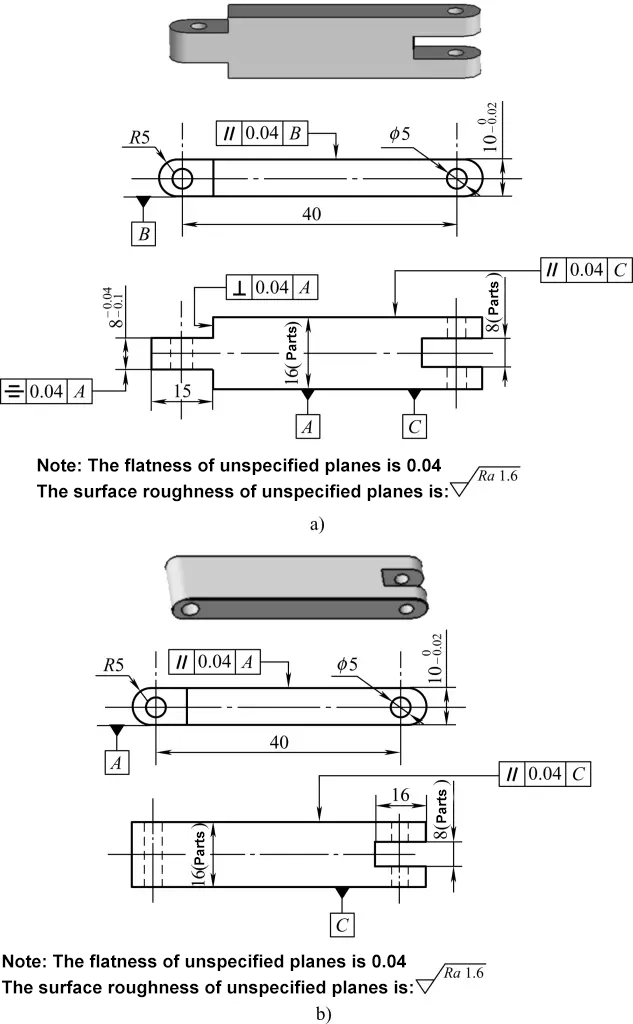
a) Measuring Block One
b) Measuring Block Two
(1) Filing Technical Requirements
1) According to usage requirements, the two measuring blocks should slide smoothly within the ruler body groove and cannot wobble left and right. Therefore, after filing the two measuring blocks, they should meet:
① After filing the sides of the two measuring blocks, they should meet the dimensional and shape accuracy requirements shown in Figure 7 (requirements for fitting between the measuring block and the two inner sides of the ruler body groove).
After filing the hinged part of the two measuring block ends, it should meet the dimensional and shape accuracy requirements shown in Figure 7 (requirements for the fit of the convex and concave parts of the measuring block ends).
After filing the hinged part of the measuring block two and the movable measuring rod end, it should meet the dimensional and shape accuracy requirements shown in Figure 7 (requirements for the fit of the convex and concave parts of the measuring block ends).
According to the usage requirements, the bottom surfaces of the two measuring blocks should contact well with the bottom surface of the ruler groove. That is, when the feeler gauge is not in use (the movable sleeve is not turned), the upper surface of the measuring block should be on the same horizontal plane as the upper plane of the ruler body. Thus, after filing the measuring block, the upper and lower surfaces should meet the dimensional and shape accuracy requirements shown in Figure 7.
Filing tools
Depending on the shape and size of the two measuring blocks, the files to be selected for filing should be a 10″, 6″, and 4″ flat file, and the non-working edges of the 4″ flat file should be polished; a set of shaping files.
Filing process
Prepare materials
Prepare a block of rough steel material (20 steel) measuring 18mm × 10mm × 110mm.
File the rectangular prism (see Figure 8)
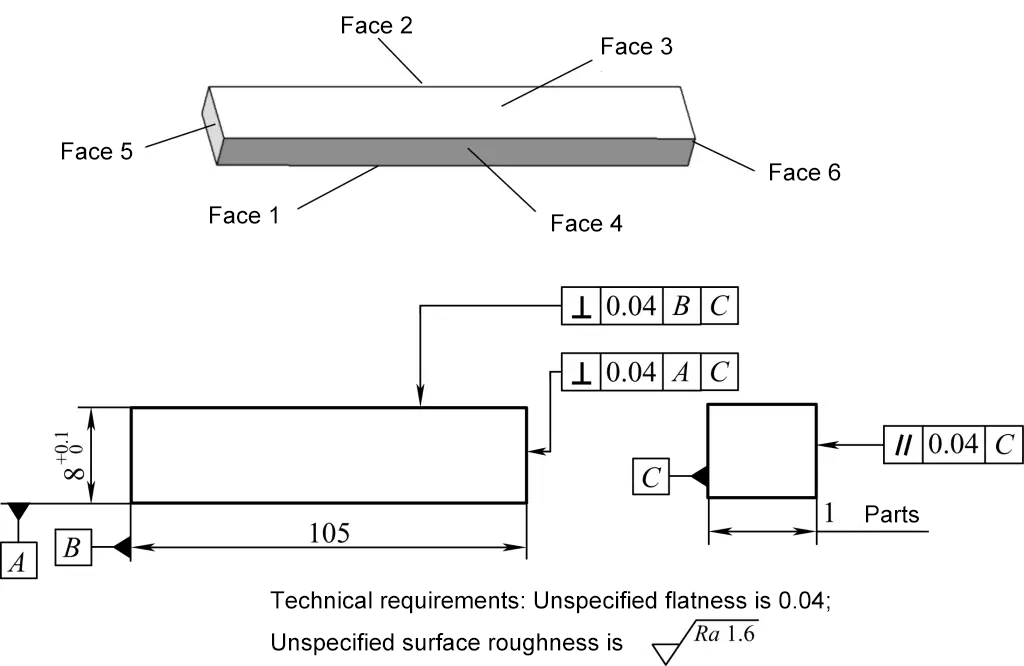
First file surface 1 flat, using a knife edge ruler to control its flatness, with precision controlled within 0.04mm, while ensuring that the surface roughness value of surface 1 is within Ra1.6μm.
Use surface 1 as the reference to mark the processing boundary of surface 3, file surface 3 to meet the size and geometric tolerance requirements as shown in Figure 8.
File surface 2, with flatness and surface roughness control similar to surface 1, and control the perpendicularity of surface 2 to surface 1 (see Figure 8).
As shown in Figure 9, file surface 4 according to the actual size of the ruler groove, controlling the dimension to 16mm, achieving a fit clearance between the ruler groove and the 16mm dimension direction of 0.04mm

File both end surfaces 5 and 6, with emphasis on controlling the perpendicularity of surface 5 to surfaces 1 and 2, and the perpendicularity of surface 6 to surfaces 1 and 2, controlling the total length to 105mm.
Split the rectangular prism, dividing it into part one and part two, as shown in Figure 10.

Process measuring block one
- File an 8mm × 16mm groove (according to the filing fit of the movable measuring rod end, see Figure 7, Figure 9), requiring the gap between the movable measuring rod and the 8mm × 16mm groove sides to be: 0.04mm
- File the outer arc of the groove end to R5mm, to a total length of 50mm.
- File an 8mm × 15mm end arc to R5mm.
- File the 8mm × 15mm end boss to meet the dimensional and shape precision shown in Figure 7.
Process measuring block two (see Figure 7b, Figure 9)
Process an 8mm × 16mm groove, with the same method as part one groove. Focus on controlling the fit clearance of the groove with part one’s boss to be 0.04mm
File the left and right end arcs of part two to R5mm, to a total length of 50mm.
3. Analysis of Part Filing Fit Example – Part One
The insulator pin puller shown in Figure 11 is a commonly used homemade tool in transmission line maintenance and installation. Here is a description of the manufacturing process of its plier body:
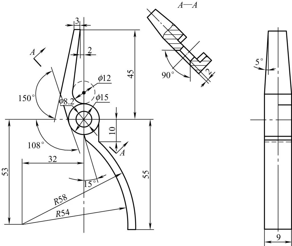
Prepare materials
The dimensions of the strip 35 steel plate are 110mm×20mm×10mm (thickness), as shown in Figure 12.
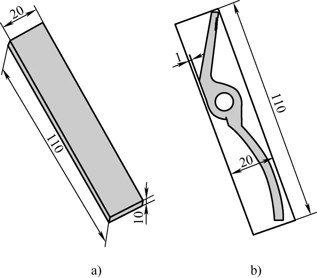
a) Blank dimensions
b) Shape after forming
(2) Filing strip plate blanks (see Figure 13)
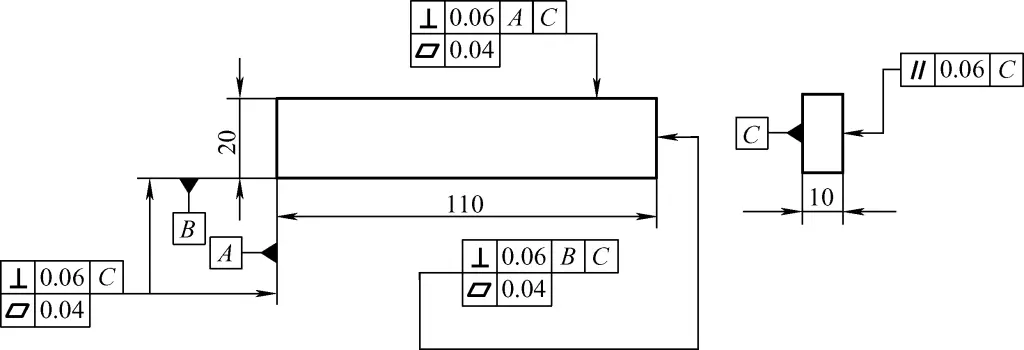
- File the A surface of the strip plate, with flatness of 0.04mm, perpendicular to C.
- File the B surface of the strip plate, with flatness of 0.04mm, perpendicular to A and C.
- Use A and B as references (both scribing and measuring references), file the opposite sides of reference surfaces A and B to achieve a flatness of 0.06mm and the required perpendicularity.
(3) Hole processing (see Figure 14)
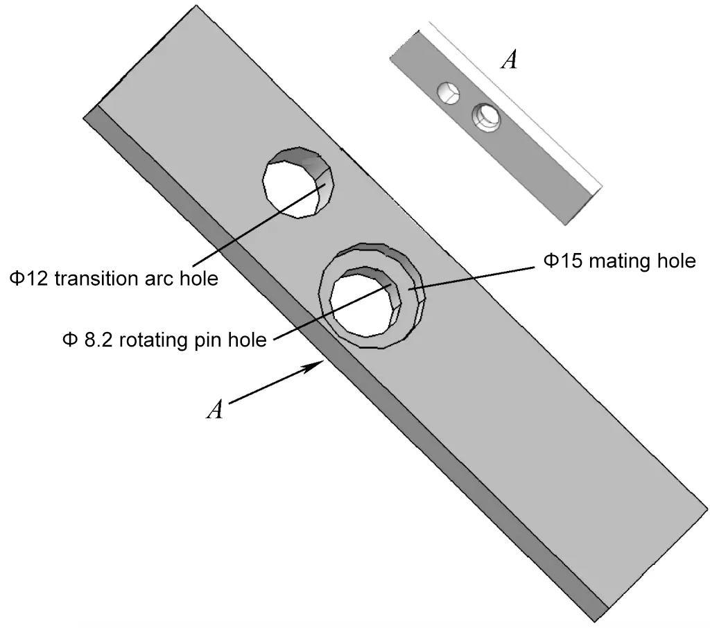
- Based on the drawing dimensions, mark the positions and diameters of the ϕ8.2mm pivot pin hole and the ϕ12mm transition arc hole.
- Drill ϕ8.2mm and ϕ12mm holes on the strip plate blank as shown in Figure 14.
- As shown in Figures 14 and 11, use a conical countersink drill to countersink the upper cone for the ϕ8.2mm (used for pin removal pliers).
- Use a ϕ15mm flat-bottom cylindrical countersink drill to countersink a ϕ15mm fit hole to a depth of 4.5mm, as shown in Figure 14.
(4) Outline marking of insulator pin extractor (see Figure 15)
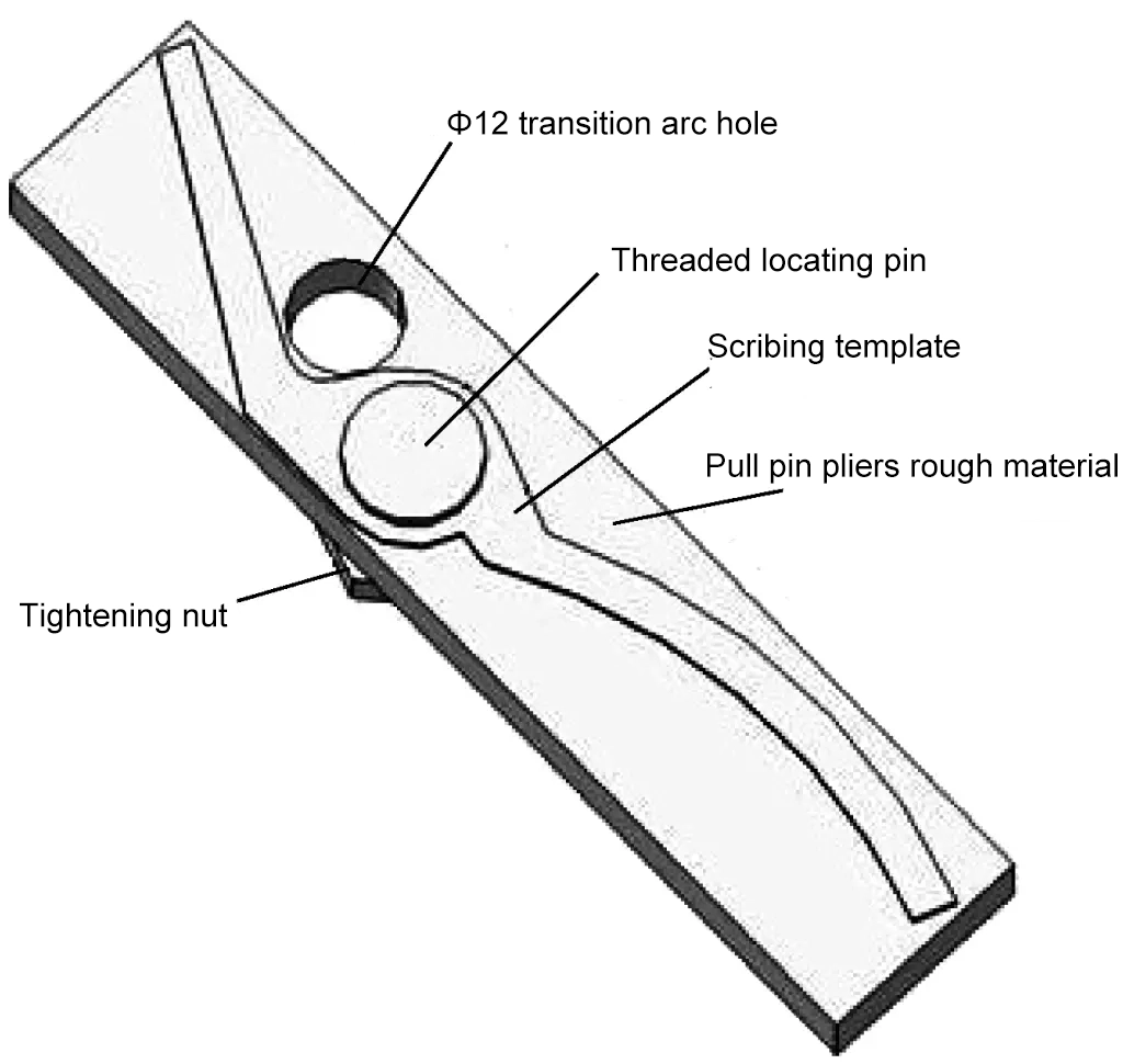
1) Align the ϕ8.2mm pivot pin hole on the template with the ϕ8.2mm hole on the strip plate blank, insert the threaded locating pin, and use a nut to secure the scribing template and the strip blank together.
2) Use a scribe to mark the contour lines for the ejector pliers along the template.
(5) Material Removal
According to the processing line marked on the template, remove the excess material using sawing or drilling, being especially careful not to use a chisel, as this will deform the plier body.
(6) Overall filing of the insulator pin pliers
The processing sequence for the overall filing of the insulator pin remover pliers is shown in Figure 16. When processing the inner side of the pliers’ jaws, ensure the inner side contour is tangent to the ϕ12mm connecting arc.
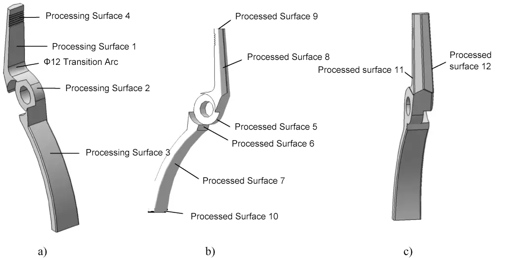
a) Step one
b) Step two
c) Step three

