Top 10 Plate Rolling Machine Manufacturers in 2024
Why do some manufacturers dominate the plate rolling machine industry while others struggle? This article dives into the top 10…
What keeps a skyscraper standing tall and a car’s frame firmly intact? It’s the diverse methods of connecting metal parts. From welding’s seamless fusion to riveting’s enduring joints, metalworking connection techniques are fundamental to modern engineering. This article explores four key methods: welding, riveting, bolting, and adhesive bonding. Each method has unique applications, advantages, and challenges. By the end, you’ll understand how these techniques shape everything from everyday objects to monumental structures. Dive in to discover the backbone of metal construction.
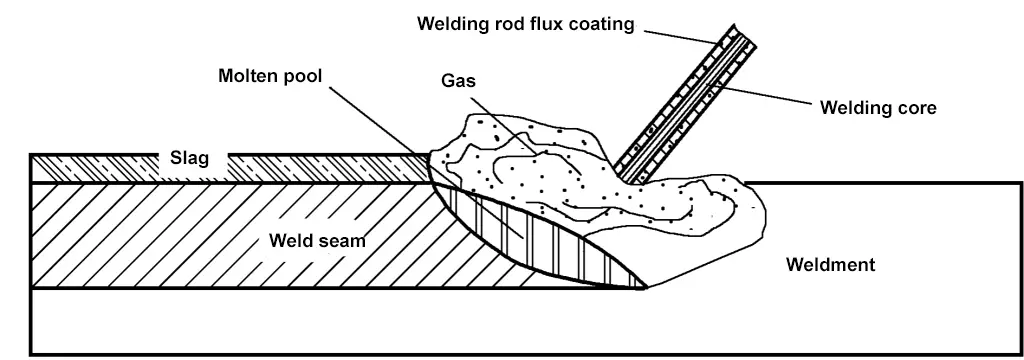
Shielded metal arc welding is a basic fusion welding method that uses manual operation of the electrode, utilizing the welding arc generated between the electrode and the workpiece to heat and melt the base metal or electrode at the welding spot to form a weld seam, as shown in Figure 7-1.
1) The process is flexible and highly adaptable. During welding, manual operation can control the arc length, electrode angle, welding speed, etc., suitable for various metal materials, thicknesses, structural shapes, and positions.
2) It is easy to disperse welding stress and control welding deformation by changing process operations.
3) Compared to methods like gas shielded welding and submerged arc welding, the equipment is simple, maintenance is convenient, and production costs are lower.
4) Low production efficiency, high labor intensity, and welding quality require a high level of operator skill and experience.
Shielded metal arc welding is widely used in various sectors of the national economy. It can be used to weld carbon steel, low alloy steel, heat-resistant steel, and stainless steel. It is also suitable for welding high alloy steel, cast iron, non-ferrous metals, dissimilar steels, and for surfacing of various metal materials.
An electrode is a welding material coated with flux for use in shielded metal arc welding. During welding, the electrode serves two roles: as an electrode and as a filler metal, which melts and fuses with the base material to form a weld seam.
There are many types of electrodes, each with its application scope. The appropriate selection of electrodes has a significant impact on welding quality, product cost, and labor productivity. The following principles should be followed when selecting electrodes:
1) Select based on the mechanical properties and chemical composition of the base material. When welding base materials such as low carbon steel, medium carbon steel, or ordinary low alloy steel, choose an electrode with corresponding strength to ensure the weld seam has the same performance as the base material.
2) For important structures requiring high toughness and ductility in the weld seam, or for steel with a high tendency to crack and high rigidity, choose basic electrodes, high toughness electrodes, or even ultra-low hydrogen electrodes.
3) When selecting electrodes for welding stainless steel, molybdenum, and chromium-molybdenum heat-resistant steel or for surfacing, start from ensuring the special performance of the welded joint, requiring the chemical composition and type of the weld metal to be the same or similar to the base material.
4) For welding dissimilar metal joints between low carbon steel and low alloy steel, choose an electrode with one strength level lower.
4) For welding dissimilar metal joints between low carbon steel and low alloy steel, choose an electrode with one strength level lower.
5) Select electrodes based on existing equipment and construction conditions. Preferably use electrodes suitable for both AC and DC. If the bevel surface of the workpiece is difficult to clean, use acid electrodes that are strongly oxidative and insensitive to rust and oil stains; in enclosed containers or under conditions with poor ventilation, use acid electrodes that emit less harmful gases during welding.
6) Consider the crack resistance of the weld metal. When the welded structure has high rigidity, large thickness, and complex shape, use crack-resistant basic low-hydrogen electrodes.
7) When the welded parts are subjected to vibrational or impact loads, in addition to ensuring strength, use basic electrodes with better plasticity and toughness.
8) When selecting based on simplified processes, productivity, and cost-effectiveness, try to use electrodes that produce less dust and harm and are inexpensive. For welded parts with a large amount of welding work, use larger, more efficient electrodes, such as high-efficiency stainless steel electrodes and gravity electrodes, while ensuring welding performance.
Uneven heating and shrinkage during the welding process are the main causes of residual stress, and residual stress is the main cause of structural deformation.
In actual production, the deformation of welded structures is quite complex. According to the impact of welding residual deformation on the entire structure, it can be divided into two categories: one is local deformation, which occurs in some parts of the welded structure, as shown in Figure 7-2; the other is overall deformation, which causes changes in the shape and size of the entire welded structure, as shown in Figure 7-3.
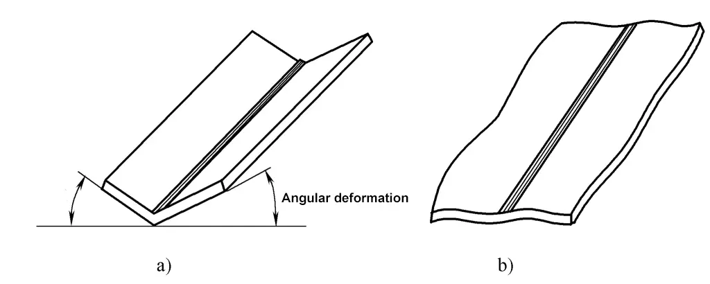
a) Angular deformation
b) Wavy edge shape
According to the characteristics of welding residual deformation, it can be divided into six basic forms of deformation: shrinkage deformation, angular deformation, bending deformation, wavy deformation, torsional deformation, and misalignment deformation, as shown in Figures 7-2 and 7-3.
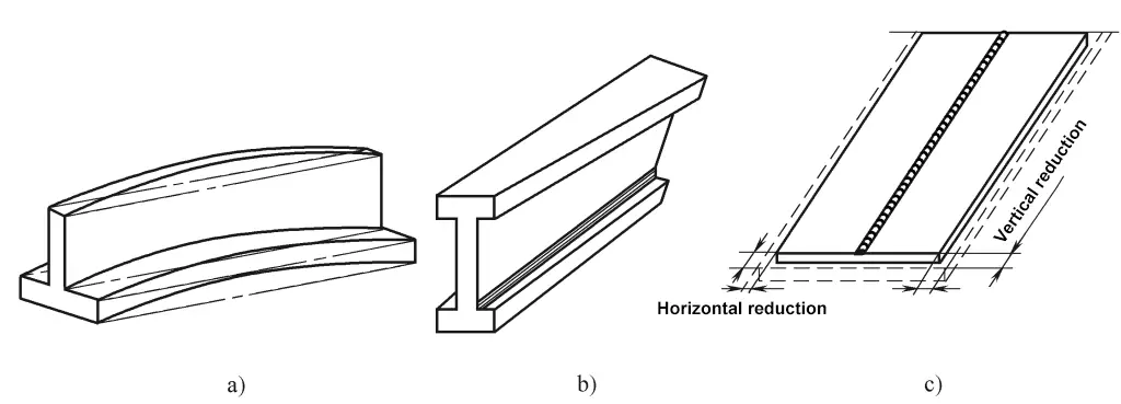
a) Bending deformation
b) Torsional deformation
c) Shrinkage deformation
To control welding residual deformation, consider the following commonly used measures from a process perspective:
(1) Use a reasonable assembly welding sequence
1) Use symmetrical welding method for symmetrical welds
Since welding always has a sequence, and as the welding process progresses, the rigidity of the structure also increases. Therefore, welds that are welded first tend to cause deformation of the structure. Thus, even if the structure of the welds is symmetrical, welding deformation will occur after welding. The purpose of symmetrical welding is to overcome or reduce the deformation caused by the first welded seam when the rigidity of the welded part is low.
2) Weld the side with fewer seams first for asymmetric welds
For structures with asymmetric welds, weld the side with fewer seams first, then the side with more seams. This can allow the deformation from the later welding to offset the deformation from the earlier welded side, reducing overall deformation.
3) Use different welding sequences to control welding deformation
For long welds in structures, if continuous through welding is used, it will cause significant deformation. This is not only due to the direction of welding but also because the weld is heated for a long time. If possible, changing continuous welding to segmental welding and appropriately changing the welding direction can reduce the deformation caused by local welds or offset each other to achieve the purpose of reducing overall deformation. As shown in Figure 7-4.
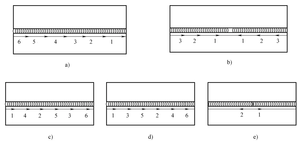
a) Step-back welding method
b) Center-step-back welding method
c) Skip welding method
d) Alternating welding method
e) Mid-section butt welding method
(2) Counter deformation method
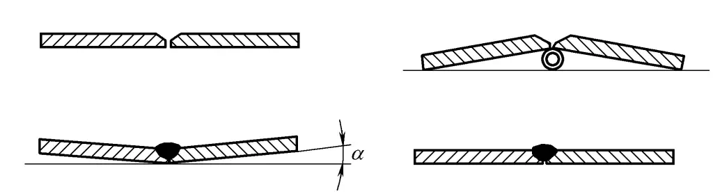
According to the deformation pattern of the weldment, artificially place the weldment in a deformation opposite to the welding deformation direction in advance, in order to achieve the purpose of counteracting the welding deformation. This method is called the counter deformation method (also known as the reserved allowance method). Using this method requires experience in predicting the size of the counter deformation, and the angle of reverse bending should be controlled, not too small or too large. The Y-shaped groove butt welding shown in Figure 7-5 is an example of controlling angular deformation using the counter deformation method.
(3) Rigid fixation method
The amount of deformation of the weldment depends on the rigidity of the structure; the greater the rigidity, the smaller the deformation caused after welding, and the rigidity of the structure mainly depends on the shape and size of the structure. In terms of the structure’s ability to resist tension or compression, the size of the rigidity is related to the size of the cross-sectional area.
The larger the cross-sectional area, the greater the rigidity, and the stronger the ability to resist deformation. Therefore, thick steel plates have less deformation after welding compared to thin steel plates.
The rigid fixation method is to use compulsory measures or rely on fixtures with strong rigidity for components that lack sufficient rigidity themselves, to limit and reduce the degree of deformation after welding. With this method, the fixed fixtures can only be removed after the weldment has completely cooled. Figures 7-6 to 7-8 show examples of different welded structures using the rigid fixation method to reduce welding deformation.
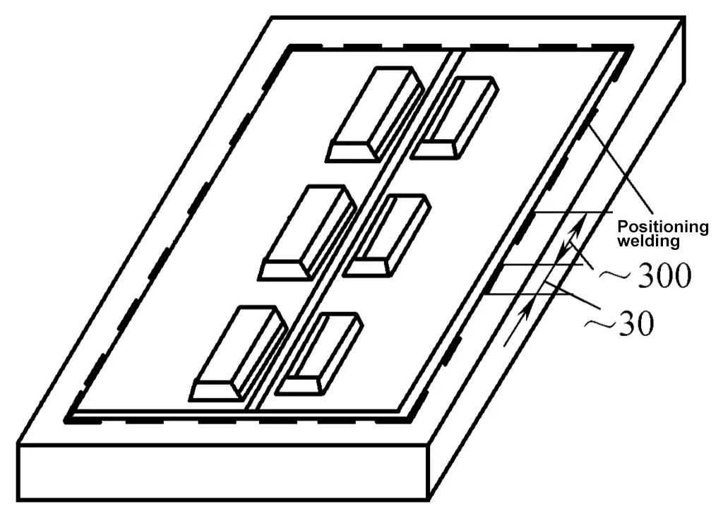
1) Use heavy objects for pressing or use tack welding for positioning. This method is suitable for thin plate welding, where tack welding is used around the plate to weld it firmly to the platform or frame, and heavy objects are placed on both sides of the weld seam. After the weld seam has completely cooled, remove the heavy objects, scrape off the tack weld points, and achieve the purpose of reducing deformation. As shown in Figure 7-6.
2) Use fixtures for fixation. As shown in Figure 7-7a, before welding the I-beam, bolt the flanges firmly onto the platform, using the rigidity of the platform to reduce angular deformation and bending deformation after welding.
If conditions limit the use of the above method, the method shown in Figure 7-7b can also be used, combining two I-beams together, using wedge clamps to tighten the two flanges, increasing the rigidity of the I-frame to achieve the purpose of reducing deformation after welding. This method is also commonly used in the assembly welding of bases, frames, and other components.
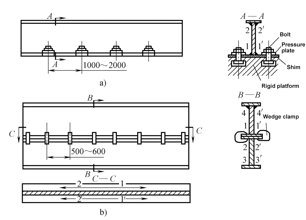
a) One I-beam
b) Combination of two I-beams
3) Use “sawhorses” or temporary supports for fixation. In butt welding of steel plates, the method of fixing with “sawhorses” can also be used to control deformation, which is a simple and reliable method widely used in production. For general small weldments, the rigid fixation method with temporary supports can also be used, as shown in Figure 7-8.
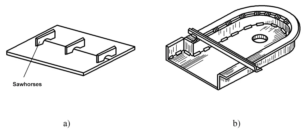
a) Fixation method using “sawhorses”
b) Fixation method using temporary supports
It should be noted that although welding deformation is effectively controlled with rigid fixation, due to the large constraints on the structure, significant internal stresses are generated. Therefore, rigid fixation is only suitable for weldments with good weldability. For medium carbon steel and alloy steel with poor weldability, rigid fixation should not be used for welding to avoid cracking.
Additionally, choosing reasonable welding methods and parameters can also reduce welding deformation. For example, using concentrated heat, narrow heat-affected zone CO, gas shielded welding, plasma arc welding instead of gas welding and shielded metal arc welding can reduce welding deformation; using smaller welding parameters to reduce heat input can also reduce welding deformation.
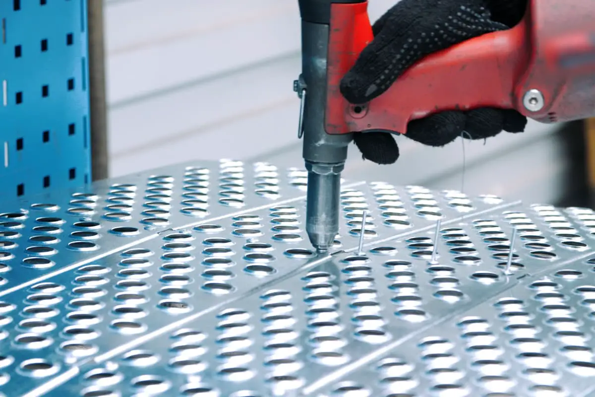
Riveting refers to the method of connecting two or more pieces of the same or different materials with rivet holes processed into a whole using riveting tools and equipment, utilizing the deformation of rivets at room temperature or after heating.
The general workflow of riveting is as follows:
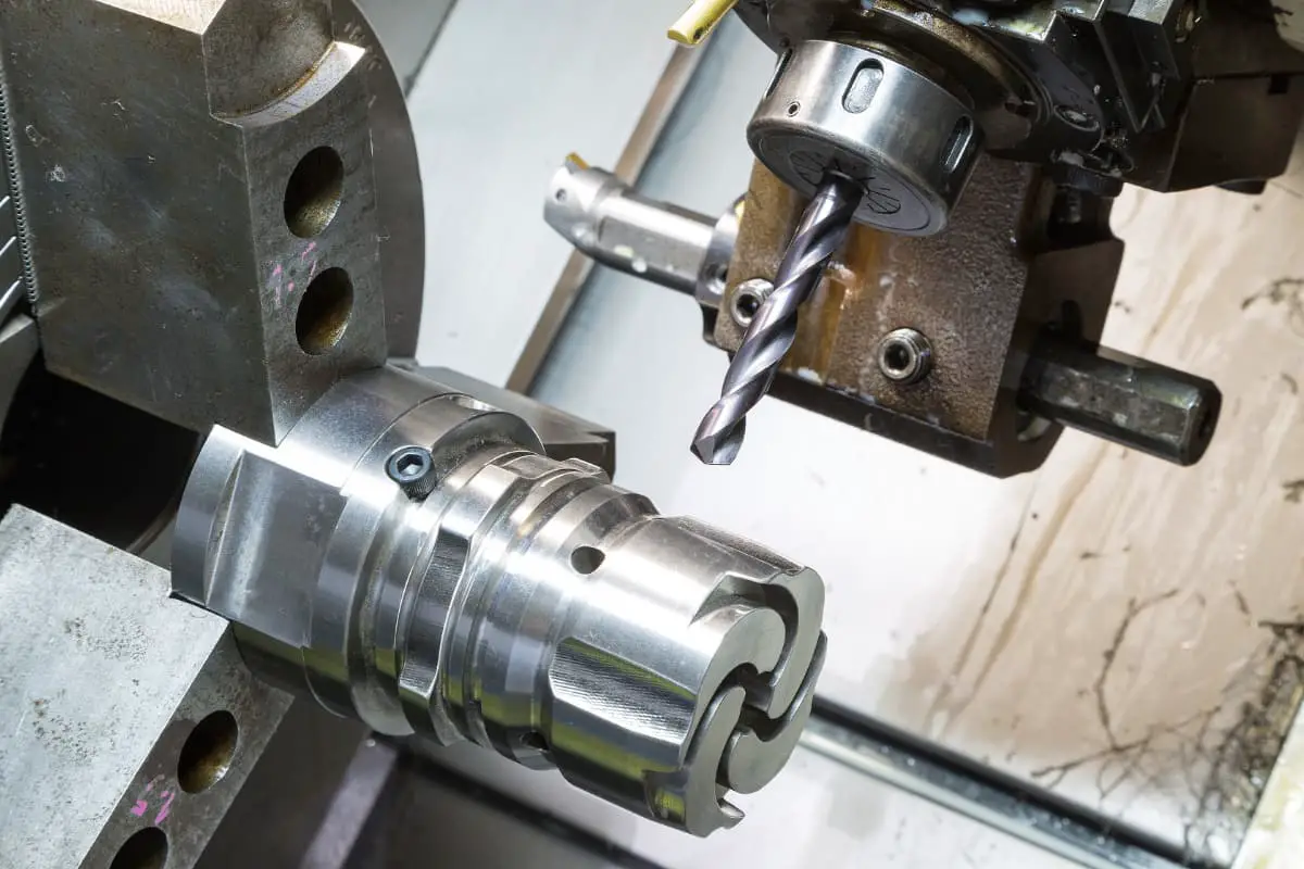
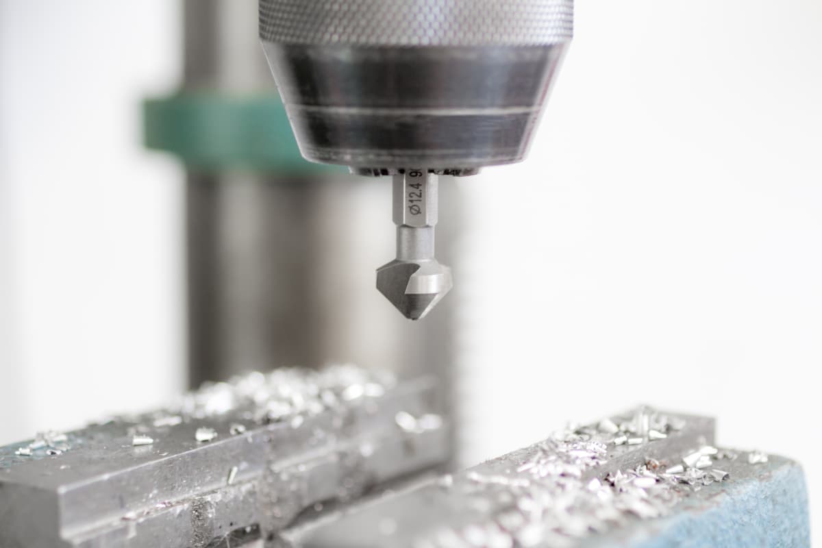
1) Use drilling, reaming, broaching, and reaming to process rivet holes on the connecting parts.
2) According to the structural drawing size requirements, select the assembly reference for the positioning of the riveted parts.
3) Correctly select rivets that meet technical requirements.
4) Determine the riveting equipment and tools.
5) Implement the riveting operations of burning, joining, threading, and topping.
6) Inspection of riveting quality.
Riveting features simple process equipment, even and reliable stress distribution, minimal deformation after assembly, high strength, easy quality control, convenient inspection, joints that are not prone to loosening, long service life, and ease of maintenance and inspection. It is a non-detachable connection, commonly used in connections that need to withstand large impact loads and vibration loads, poor weldability, or non-metallic materials.
With the development of industrial technology, riveting has gradually been replaced by welding and bonding due to its disadvantages such as multiple processes, high labor intensity, high noise, and low work efficiency, but it is still widely used in industries such as automotive, aviation, instrumentation, bridges, and construction.
Depending on the working performance of the components and the scope of application, riveting can be divided into:
(1) Strong riveting
Only requires the rivets and components to have sufficient strength to withstand large loads, with no special requirements for the tightness of the joint. Such as bridges, beams, vehicles, and towers and other truss components.
(2) Tight riveting
Requires not only sufficient connection strength to withstand certain forces but also good tightness of the joint to ensure that no liquids or gases leak under certain pressures. This type of riveting is commonly used in high-pressure vessel components, such as boilers, gas tanks, etc.
(3) Tight riveting
The joint does not bear significant force, it only requires high tightness to prevent water and air leakage, mostly used in the connection of thin-walled container components, such as water tanks, oil tanks, etc.
According to the different relative positions of the connected parts, it is divided into three forms: lap, butt, and corner joints.
(1) Lap
One sheet is riveted on top of another sheet, as shown in Figure 7-9.
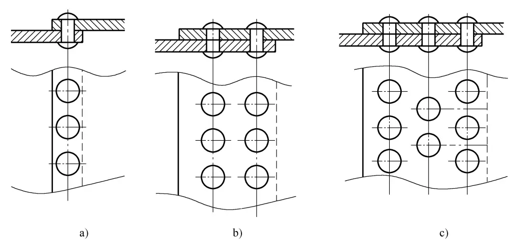
a) Single row
b) Double row
c) Multiple rows
(2) Butt joint
Riveting is performed by placing the joints of two plates on the same plane and using a cover plate as a connector to join the joints together. There are two types of cover plates: single and double, each further divided into single row, double row, and multiple rows according to the number of rows of rivets. The arrangement of rivets can be either parallel or staggered, as shown in Figure 7-10.
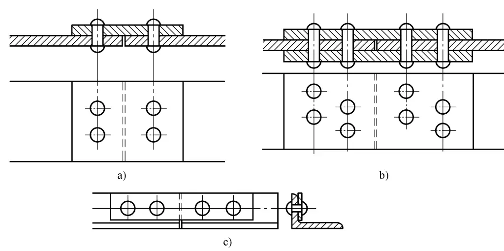
a) Single row, single cover plate
b) Double row, double cover plate
c) Angle iron butt joint
(3) Corner joint
Connects two plates that are perpendicular or at a certain angle to each other, usually using angle iron as the connector, available in single-sided and double-sided forms, as shown in Figure 7-11.
a) Single-sided corner joint
b) Double-sided angle docking
Basic parameters refer to rivet spacing, row spacing, and edge distance, as shown in Figure 7-12.
1) Rivet spacing t: The distance between the centers of two adjacent rivets in the same row.
2) Row spacing c: The distance between the centers of two adjacent rows of rivets.
3) Edge distance e: The distance from the outermost row of rivets to the edge of the working plate.
Determination of rivet arrangement parameters on steel plates, see Table 7-1.
Table 7-1 Determination of rivet arrangement parameters on steel plates
| Name | Location and orientation | Maximum allowable distance (take the minimum of the two) | Minimum allowable distance | |
| Rivet distance t or pitch c | Outer row | 8d 0 or 12δ | 3d0 | |
| Middle row | Component under compression | 12d 0 or 18δ | ||
| Component under compression | 16d 0 or 24δ | |||
| Margin e | Parallel to the load direction e 1 | 4d 0 or 8δ | 2d0 | |
| Direction perpendicular to the load e 2 | Cutting edge | 1.5d0 | ||
| Rolling edge | 1.2d0 | |||
Note: d 0 is the diameter of the rivet hole; δ is the thickness of the thinner plate
A rivet consists of a rivet head and a cylindrical shank, with the rivet head often forged from dies, available in solid and hollow types. Solid rivets are divided into various forms such as round head, countersunk, semi-countersunk, flat cone head, and flat head; hollow rivets are light and convenient for riveting but have low head strength, suitable for structures under less stress.
According to GB/T116-1986, steel rivets include Q215, Q235, ML2, ML3, 10, 15, copper rivets include T3, H62, and aluminum rivets include L3, LY1, LY10, LF10 (use the new material grades, complying with the national standard regulations for rivets).
During the riveting process, as the rivet needs to withstand significant plastic deformation, the rivet material must have good plasticity. For this reason, rivets made by cold heading need to be annealed. According to the requirements, the rivets should undergo forgeability tests and mechanical strength tests such as tensile and shear. The surface of the rivet should not have any defects that affect its use.
The diameter of the rivet is determined by the thickness of the connector plate according to the structural strength requirements, and the relationship between the component plate thickness δ and the rivet diameter d is generally as follows:
1) For single and double row lap joints, d≈2δ.
2) For single and double row cover plate connections, d≈(1.5~1.75)δ.
The diameter of the rivet can also be determined according to Table 7-2.
Table 7-2 Determination of Rivet Diameter (Unit: mm)
| Plate Thickness δ | 5~6 | 7~9 | 9.5 ~12.5 | 13 ~18 | 19 ~24 | >25 |
| Rivet Diameter d | 10 ~12 | 14 ~25 | 20 ~22 | 24~27 | 27~30 | 30 ~36 |
The following principles must be followed when determining the rivet diameter based on plate thickness:
1) When lapping plates with similar thicknesses, take the thickness of the thicker plate.
2) When lapping plates with significantly different thicknesses, take the thickness of the thinner plate.
When connecting plates and profiles, take the average thickness of both.
The total thickness of the connected parts should not exceed 5 times the diameter of the rivet.
The quality of riveting is directly related to the selected length of the rivet rod. If the rod is too long, the rivet’s head will be too large, and the rod is likely to bend; if the rod is too short, there will be insufficient upset, and the rivet head will not be fully formed, severely affecting the strength and tightness of the riveting.
The length of the rivet should be determined based on factors such as the total thickness of the parts to be connected, the clearance between the hole and the rod diameter, and the riveting process method. The length of the rivet rod with a standard hole diameter can be calculated using the following formula:
Round head rivet L = (1.65 ~ 1.75)d + 1.1∑δ
Countersunk rivet L = 0.8d + 1.1∑δ
Semi-countersunk rivet L = 1.1d + 1.1∑δ
The rivet lengths calculated above are approximate values; the actual length of the rivet rod for mass riveting needs to be determined after trial riveting.
The fit between the rivet hole diameter and the rivet should be determined based on different methods of cold and hot riveting.
During cold riveting, the shank is not easy to upset, and to ensure joint strength, the hole diameter should be close to the shank diameter.
During hot riveting, the rivet expands and thickens due to heat but remains pliable; to facilitate insertion, the difference between the hole diameter and the shank diameter should be slightly larger. See Table 7-3 for standard hole diameters. For multi-layer plate tight riveting, the drilling diameter should be reduced by 1~2mm according to the standard hole size, and for cylindrical components, holes must be drilled before bending, and the hole diameter should be reduced by 1~2mm from the standard to allow reaming during assembly.
Table 7-3 Standard rivet hole diameters (unit: mm)
| Rivet rod diameter | Hole diameter d0 | |
| Precision assembly | Rough Assembly | |
| 3.5 | 3.6 | 3.9 |
| 4 | 4.1 | 4.5 |
| 5 | 5.2 | 5.5 |
| 6 | 6.2 | 6.5 |
| 8 | 8.2 | 8.5 |
| 10 | 10.3 | 11 |
| 12 | 12.4 | 13 |
| 14 | 14.5 | 15 |
| 16 | 16.5 | 17 |
| 18 | 19 | |
| 20 | 21.5 | |
| 22 | 23.5 | |
| 24 | 25.5 | |
| 27 | 28.5 | |
| 30 | 32 | |
| 36 | 38 | |
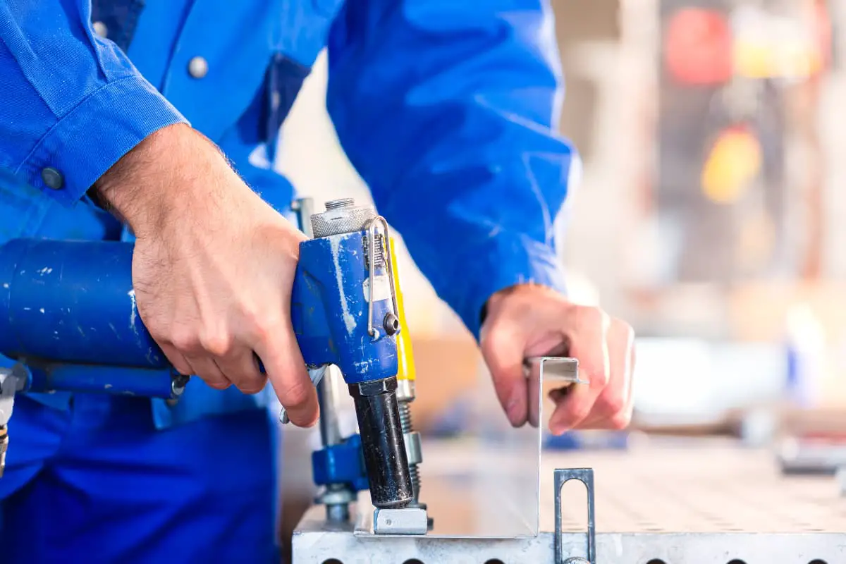
The rivet gun is the main tool for welding. Also known as an air gun, as shown in Figure 7-13. It mainly consists of a handle 2, gun body 4, switch 3, and tube connector 1. Various rivet dies or punches can be installed in the hole at the front end of the gun body for riveting or punching operations. When in use, the die is usually tied to the handle with fine steel wire to prevent the piston from sliding out when the die detaches from the gun body as the gun is lifted.
1—Tube Connector
2—Handle
3—Switch
4—Gun Body
5—Die
6—Flat head rivet
7—Punch
Before using the rivet gun, inject a small amount of machine oil at the air inlet joint to keep the gun body well-lubricated during operation, then blow the dirt out of the compressed air hose and connect it to the rivet gun’s hose connector. The air intake volume is controlled by the pressure regulating valve, and the pressure of the compressed air is generally 0.4~0.6MPa. The rivet gun is compact, easy to operate, and can perform various unknown riveting tasks, but it is very noisy during operation.
Different from a rivet gun, a riveting machine is a specialized equipment that uses hydraulic or pneumatic pressure to plastically deform the nail rod to form a rivet head. It has two mechanisms: riveting and top pin. Due to the high and uniform pressure produced by the riveting machine, both the quality and strength of the riveting are high, and it operates without noise.
There are two types of riveting machines: stationary and mobile. Stationary riveting machines have high production efficiency but are more expensive, thus they are only suitable for professional production; mobile riveting machines are flexible and widely used, available in hydraulic, pneumatic, and electric types.
The hydraulic riveting machine uses hydraulic principles for riveting, as shown in Figure 7-14. It consists of a frame 1, piston 5, concave head 3, top pin concave head 2, and buffer spring 9. When the hydraulic oil enters the hydraulic cylinder through the pipe joint 8, it pushes the piston downward. The lower end of the piston has a concave head 3, and the rivet is pressed between the upper and lower concave heads to form the rivet head.
1—Frame
2—Top pin concave head
3—Concave head
4—Hydraulic cylinder
5—Piston
6—Seal pad
7—Spring
8—Pipe fitting
9—Buffer spring
When the piston moves downward, spring 7 is compressed and deformed. After the riveting is completed, the piston is reset by the elasticity of the spring. The function of the seal pad 6 is to prevent oil leakage from the piston. The entire riveting machine can be moved by a crane, and to prevent vibration during riveting, the spring at the lifting ring can be used for buffering.
Riveting is divided into cold riveting and hot riveting based on temperature; this section mainly introduces hot riveting.
Riveting at room temperature is called cold riveting. Cold riveting requires the rivet to have good plasticity. When using a riveting machine for cold riveting, the maximum rivet diameter should not exceed 25mm. When using a rivet gun for cold riveting, the rivet diameter is generally below 12mm.
Riveting after heating the rivet is called hot riveting. After heating, the strength of the rivet shank decreases, plasticity increases, and the rivet head is easily formed. The external force required for riveting is significantly reduced compared to cold riveting, so hot riveting is commonly used for larger diameter rivets or mass riveting.
During hot riveting, besides forming a sealed rivet head, one end of the rivet shank is also upset to fill the rivet hole. Upon cooling, the rivet contracts in length, exerting sufficient pressure on the riveted parts, making the seam tighter and thus achieving sufficient joint strength.
The basic process of hot riveting is as follows:
(1) Fastening of riveted parts and reaming of rivet holes
When assembling riveted parts, it is necessary to align the holes on the plates and tighten them with bolts of corresponding specifications. The distribution of bolts should be uniform, and the number should not be less than one quarter of the number of rivet holes. After tightening the bolts, the joint surfaces of the seams must be tight.
In component assembly, due to machining errors, some misaligned holes may occur, so it is necessary to ream the rivet holes with a correction punch or reamer before riveting to ensure concentricity and smooth riveting. Rivet holes that have allowances left in pre-processing should be reamed in one go. The reaming sequence is to first ream the holes without tightened bolts, then insert bolts after reaming, and finally remove the original bolts and ream the holes.
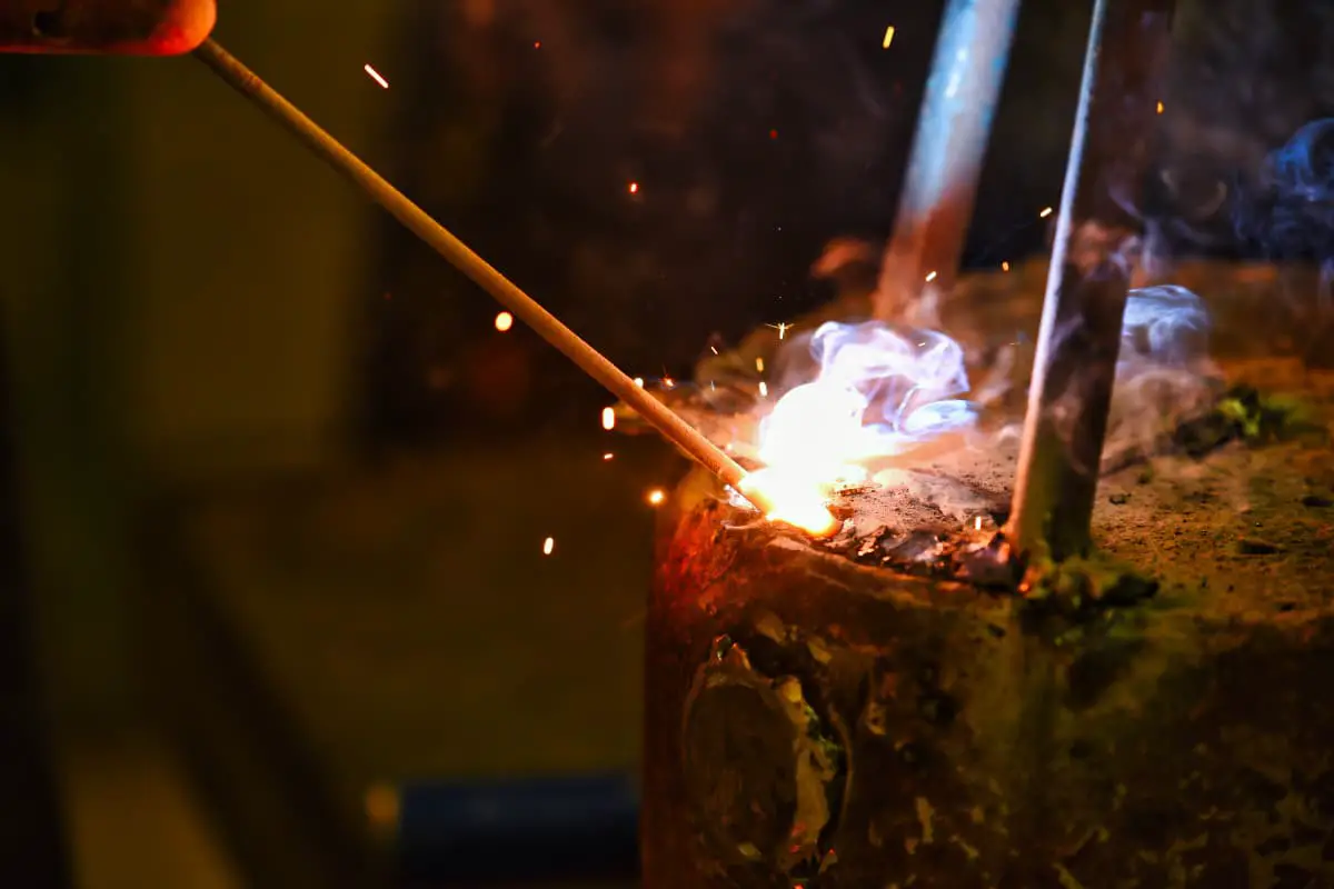
(2) Heating the rivet
When riveting with a rivet gun, the rivet needs to be heated to 1000~1100℃. During heating, the rivet is heated to an orange-yellow color (about 900~1100℃), then switched to slow fire to smolder, allowing the rivet to heat evenly throughout its length and inside, and the well-heated rivet can then be taken out for riveting (rivets that are overheated or insufficiently heated during heating cannot be used).
(3) Catching and inserting the rivet
Throw the rivet accurately, catch the rivet steadily, and quickly insert the rivet into the hole after catching, striving to complete the riveting at high temperature.
(4) Top riveting
The quality of top riveting directly affects the quality of the riveting. The concave head shape and specifications on the top handle should match the prefabricated rivet head. The “concave” should be shallower, and the top riveting should be forceful to make the formed rivet head fit tightly against the plate surface.
(5) Riveting
Initially, intermittent air supply is used in riveting, and after the nail rod is upset, the air volume is increased to forge the exposed nail rod into a rivet head shape. After the rivet head is formed, the rivet gun is slightly tilted and rotated around the rivet head for one round to force the rivet head to fit tightly with the surface of the component, but excessive tilting is not allowed to avoid damaging the surface of the component with the concave head. As shown in Figure 7-15.
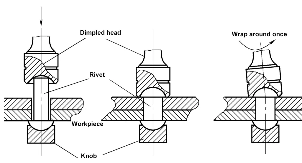
To ensure the quality of riveting, the pressure of compressed air should not be less than 0.5MPa; the final riveting temperature of the rivet should be between 450~600℃. If the final riveting temperature is too high, it will reduce the initial stress of the nail rod, preventing the riveted components from being fully tightened; if the final riveting temperature is too low, the rivet will become brittle.
Therefore, the hot riveting process should be completed as quickly as possible within a short time. For structures with high requirements for seam tightness, seam tightening is still needed after riveting. After riveting is completed, each rivet should be checked individually for quality, and those found loose and irreparable should be chiseled out and re-riveted.
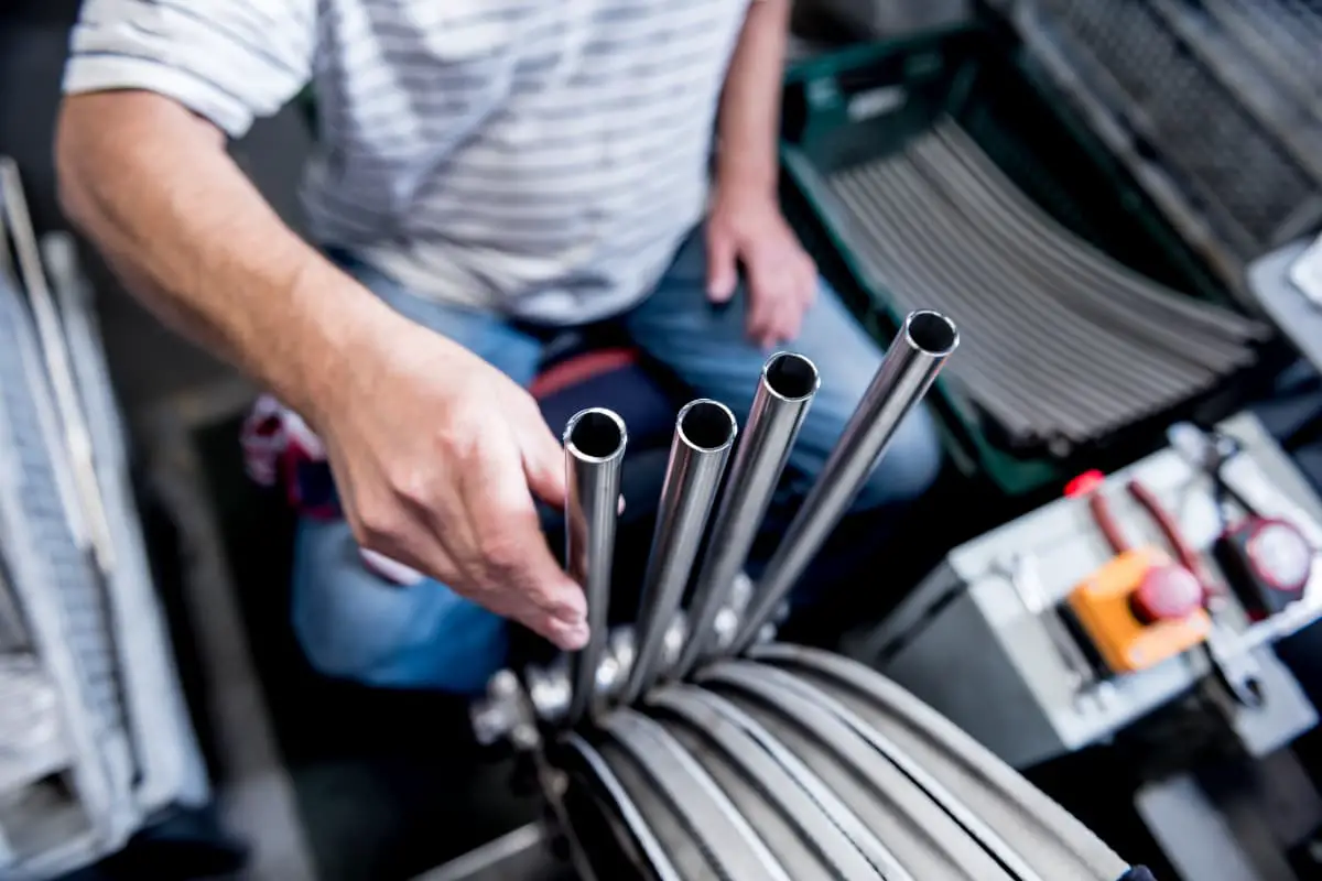
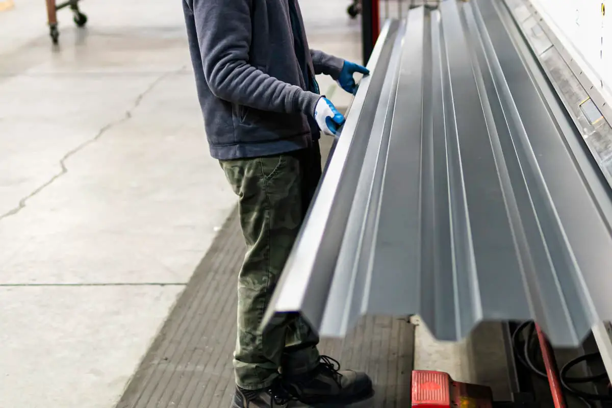
Seam biting is a method of connection where the edges of the parts to be connected are bent at a certain angle, interlocked, and then pressed against each other. Seam connections are quite robust, have good seam density, require lower demands on machinery and tools, and are easy to implement. Seam connections are often used in metal sheet structures with a thickness less than 2mm, such as in extensively used pipeline projects, where seams are used in many places to replace brazing.
Seam connections are classified by connection form into single seam, double seam, and composite seam; by seam shape into flat seam, corner seam, and vertical seam; and by seam position into longitudinal seam and transverse seam.
Seam connections are generally performed manually or with mechanical equipment. For single or small-scale production, manual seam biting is widely used to manufacture small sheet metal products, characterized by low cost and convenience.
For mass production, mechanical seam biting is used, which compared to manual seam biting has advantages such as lower noise, better seam quality, lower labor intensity for workers, and higher production efficiency (can be increased by 8~25 times), but requires a large one-time investment in equipment. Mechanical seam biting should be used as much as possible if conditions allow.
Depending on the structure and requirements of the sheet metal parts, different forms of seams are used. Common seam forms are shown in Table 7-4.
Table 7-4 Forms of seam
| Seam Name | Simplified Diagram | Seam Allowance Size | Usage | |
| Flat Seam | Flat Ordinary Seam |  | Seam Allowance is 3 times Seam Width | Used for cylindrical, conical, and rectangular tube connections. Use smooth seam if the seam needs to be attached to a flat surface or needs to be airtight; use double seam if better strength and airtightness are required. |
| Flat Smooth Seam | 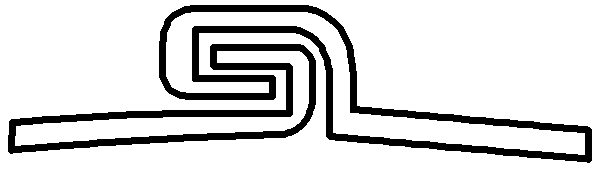 | |||
| Flat Hanging Seam |  | |||
| Flat double seam | 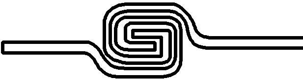 | Seam allowance is 5 times the seam width | ||
| Corner seam | Corner single seam | 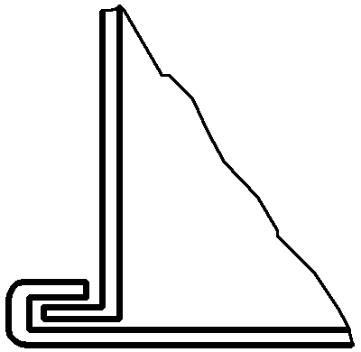 | Seam allowance is 3 times the seam width | Corner seam used in manufacturing elbow joint bends |
| Corner double seam | 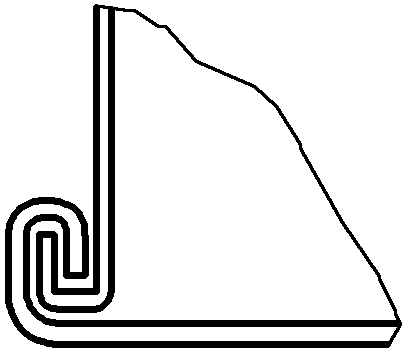 | |||
| Corner compound seam | 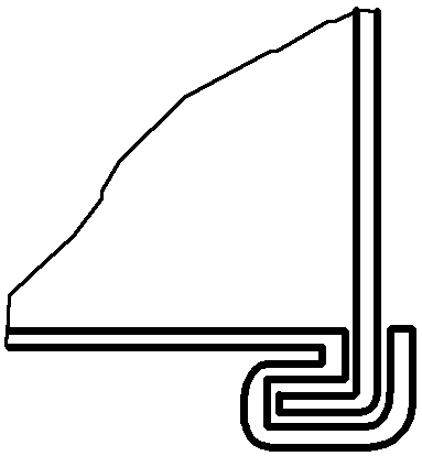 | Seam allowance is 4 times the seam width | ||
| Vertical seam | Vertical single seam |  | Seam allowance is three times the seam width | Used for various transition connections when connecting branch pipes, elbows, and transitioning from round to other cross-sections |
| Vertical double seam |  | Seam allowance is five times the seam width | ||
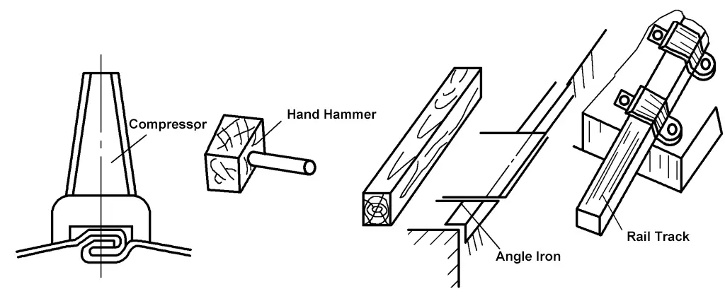
Seaming tool as shown in Figure 7-16.
The seaming by biting is usually done manually, and the general steps are as follows:
1) Calculate the seam allowance based on the type of seam.
2) Draw the seam bending line on the edge of the plate.
3) Bend the edge of the plate along the bending line.
4) Fasten and press the two sides together to complete the seam.
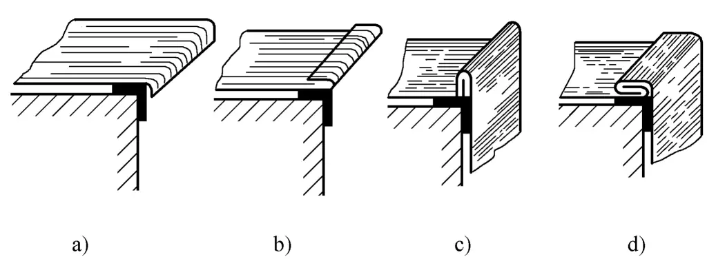
Flat single seams are generally used for connecting plates of 0.2~1.5mm thickness, with the seam width depending on the thickness of the plate. When the plate thickness is 0.2~0.5mm, the seam width is 3~5mm; when the plate thickness is 0.75~1.5mm, the seam width is between 5~8mm. The allowance for a flat single seam is three times the seam width. The seaming process is as follows:
1) Determine the seam width based on the plate thickness, and allow for a seam allowance three times the width of the seam.
2) Draw the seam bending line on the edge of the plate (one edge at the seam width; the other edge at twice the seam width).
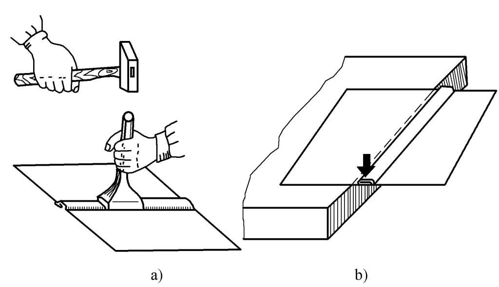
3) Align the bending line of the plate edge with the corner or edge of the square bar, and strike with a mallet to bend it at a right angle, as shown in Figure 7-17a.
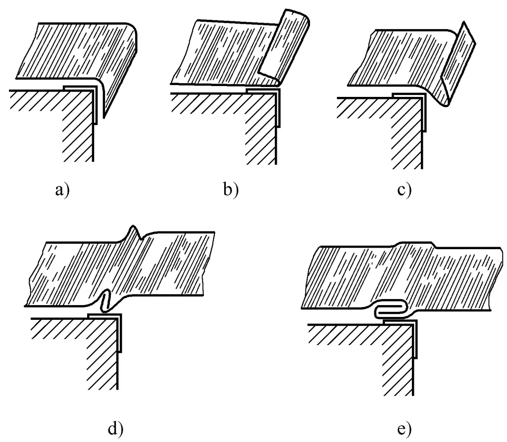
4) Flip the sheet over, use a mallet to further bend the edge of the sheet as shown in Figure 7-17b. Note that a gap larger than the thickness of the sheet should be left during bending, otherwise the other edge cannot be inserted and joined.
5) Move the sheet forward slightly more than the width of the bent edge, strike it with a mallet to bend about 45°, as shown in Figure 7-17c. The other edge is also made in the same way.
6) Buckle the two edges together and strike to compress, as shown in Figures 7-17d and 7-17e. If a flat inside or outside seam is required, it can be pressed out using a seam presser as shown in Figure 7-18a, or by using the edge of a platform or square bar as shown in Figure 7-18b.
a) Pressed out using a seam presser
b) Pressed out using the edge of a platform, square bar
The width of the corner seam is determined by the thickness of the sheet, generally between 3~8mm, with thinner sheets taking the smaller value and thicker sheets taking the larger value. The allowance for the corner seam joint is three times the width of the seam. The manufacturing process is as follows:
1) Determine the width of the seam based on the thickness of the sheet, release the joint allowance, and draw the bending line on the edge of the sheet (one side as the width of the seam; the other side as twice the width of the seam).
2) Align the bending line with the platform or the edge of the square bar, bend it into a right angle with a mallet, then flip the plate over and further bend it by hitting with a mallet (leaving a gap larger than the thickness of the plate), as shown in Figures 7-19a and 7-19b.
3) Bend another plate into a right angle, then flip it over so that the already bent plate hooks onto the straight edge, as shown in Figure 7-19c.
4) Bend and press the hooked straight edge part, as shown in Figure 7-19d.
A detachable fixed connection formed using threaded parts. Common threaded connections include bolt connection, double-headed stud connection, and screw connection, which are widely used due to their simple structure, reliable fastening, quick and convenient assembly and disassembly, and cost-effectiveness. There are many types and specifications of threaded fasteners, but their structure, form, and size have been standardized and can be found in corresponding standards.
Common tools include screwdrivers, adjustable wrenches, socket wrenches, hex keys, open-end wrenches, and spanner wrenches.
Bolt connection consists of bolts, nuts, and washers, mainly used for connections where the parts are thin and can form through holes.
There are two types of bolt connections: one is the connection that withstands axial tensile load, which allows a certain clearance between the rod of the tension bolt and the hole wall; the other is the shear bolt connection that withstands radial force, which requires strict hole diameter, needs to be reamed, and uses a transition fit or interference fit with the basic hole system for the non-threaded rod part of the bolt. Therefore, it can accurately fix the relative position of the connected parts and withstand the shearing and squeezing caused by lateral loads, as shown in Figure 7-20.
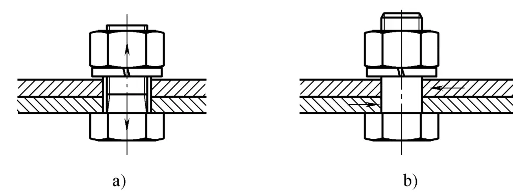
a) Tension bolt connection
b) Shear bolt connection
(1) Assembly method of bolt connection
When making a bolt connection, the specifications and quantity of bolts, nuts, and washers should be determined based on the thickness and hole diameter of the parts being connected. Generally, the length of the screw equals the combined thickness of the connected parts, nut, and washer, plus an allowance of 1~2t (t is the pitch size).
During connection, the bolt passes through the through hole on the connected part, and after adding a washer, the nut is tightened. To prevent the bolt from rotating with the nut during tightening, use wrenches to hold the bolt and nut separately and turn in opposite directions until the required tightness is achieved.
During tightening, the tightening torque must be controlled; too much torque can cause bolt elongation, breakage, and deformation of the connected parts; too little torque cannot ensure the requirements and reliability of the connection during operation.
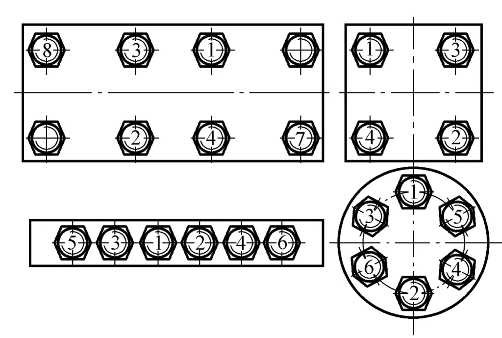
(2) Assembly sequence of grouped bolts
When tightening grouped bolts, it must be done in a certain order and gradually tightened in stages (usually in three stages) to avoid inconsistencies in tightness, uneven stress on the bolts, deformation of the fasteners, or even breaking of individual bolts under high stress. Figure 7-21 shows the tightening sequence of bolts in various assembly positions.
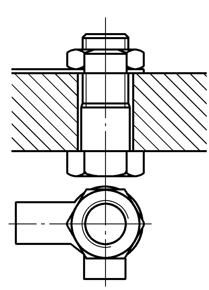
Double-ended studs are mainly used in situations where the parts are too thick for bolt connections. During connection, one end of the double-ended stud is screwed into the blind hole threads, and the other end passes through the through-hole of the connecting part, then a washer is fitted and the nut is tightened. To disassemble, unscrew the nut to separate the connected parts, as shown in Figure 7-22.
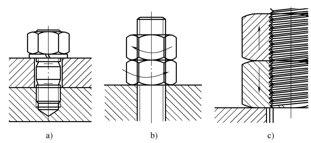
(1) Assembly method of double-ended studs Since double-ended studs do not have a fixed end, they cannot be directly tightened with the screwed-in end. Usually, the method of tightening with double nuts facing each other or a screw facing the stud is used, as shown in Figure 7-23.
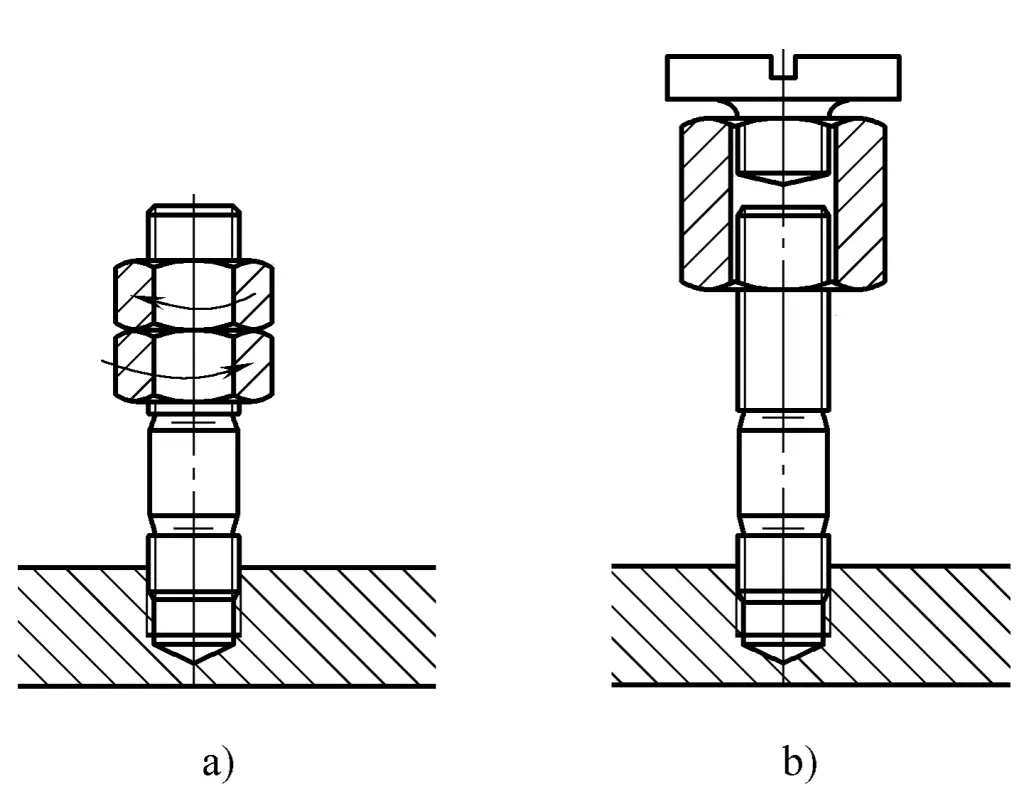
a) Double nuts facing each other
b) Screw facing the stud
(2) Assembly Precautions
1) The contact surfaces of the studs and threaded holes should be clean and dry. Tighten the bolt by hand to the end of the thread. If it cannot be screwed in, do not forcibly tighten it with a wrench to avoid damaging the threads.
2) The fit between the double-ended stud and the threaded hole should be tight enough to ensure that the stud does not loosen when the nut is removed or installed. The threading end of the stud should use a transitional fit during machining to ensure a certain amount of interference in the median diameter of the threads after fitting.
3) The centerline of the stud must be perpendicular to the surface of the connected component.
Threaded connections have a certain self-locking performance and will not loosen by themselves under static loads and minor changes in working temperature. However, in cases of impact loads, variable loads, or significant changes in working temperature, loosening may occur. To ensure connection safety and reliability and to avoid accidents caused by loosening, certain anti-loosening measures must be taken.
Common anti-loosening measures include mechanical anti-loosening and increasing frictional resistance.
(1) Mechanical anti-loosening
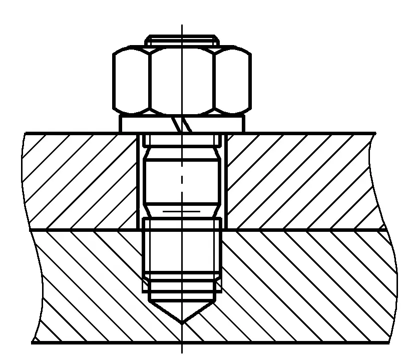
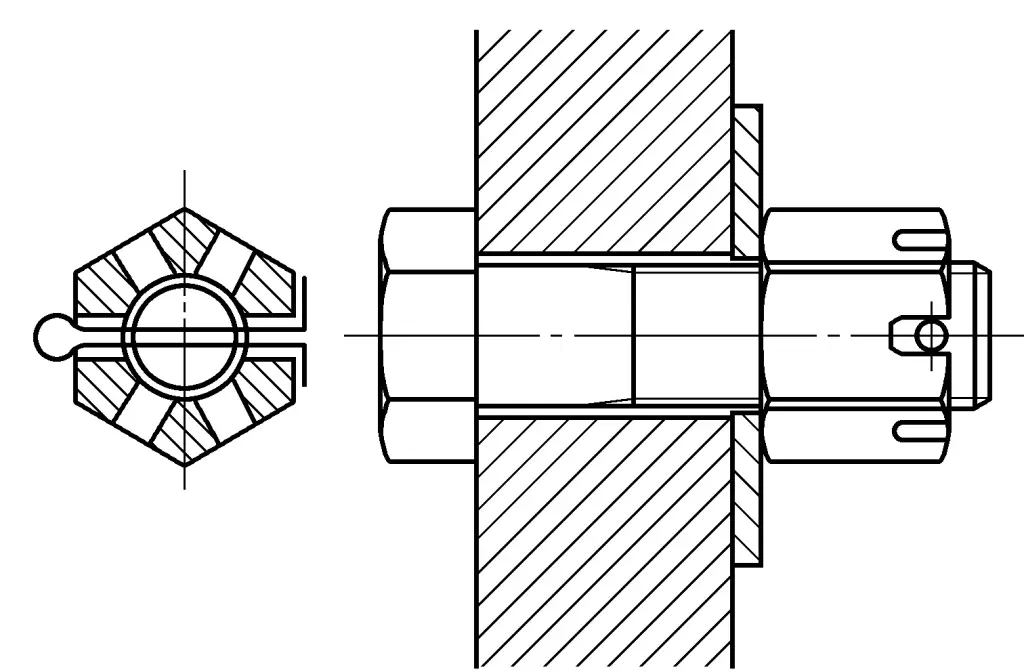
1) Cotter pin anti-loosening. As shown in Figure 7-24, pass the cotter pin through the slot on the nut and the hole on the bolt, then bend the tail end to prevent the bolt and nut from rotating relative to each other, thus achieving the purpose of anti-loosening. Cotter pin anti-loosening is commonly used in high-speed machinery under vibrational loads.
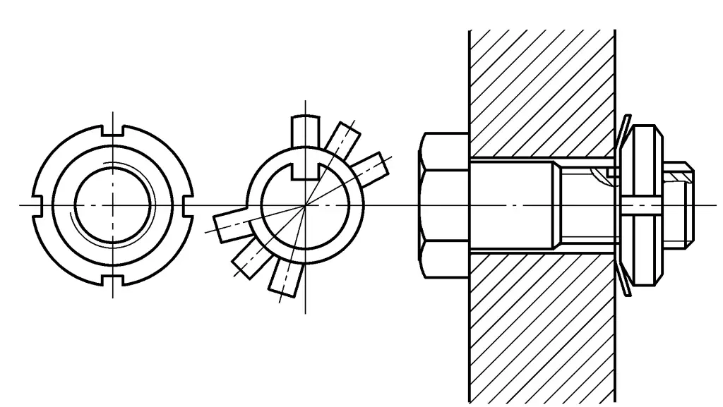
2) Stop washer anti-loosening. As shown in Figure 7-25. Insert the inner wings of the stop washer into the axial groove at the end of the external threaded part, tighten the nut, then bend the outer wings of the washer into the groove of the nut, thereby locking the nut. Used for anti-loosening in shaft-type threaded connections.
3) Lock washer anti-loosening. As shown in Figure 7-26. After tightening the nut, bend the single or double ears of the lock washer to tightly adhere to the edges of the part and the nut, preventing the nut from loosening. It can only be used where there is space to accommodate the bent ears.
(2) Increase friction to prevent loosening
As shown in Figure 7-27, apply additional axial force to increase the friction between the tightened thread surfaces to achieve the purpose of preventing loosening, mainly including spring washers and double nuts methods. However, the anti-loosening performance is unreliable and only suitable for situations with little impact and vibration.
a) Spring washer for preventing loosening
b) Double nut for preventing loosening
c) Increased friction on threaded mating surfaces
The bevel joint flat welding workpiece diagram is shown in Figure 7-28.
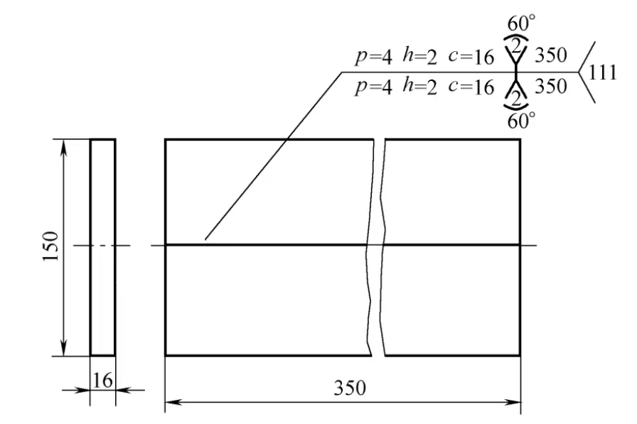
Technical Requirements
For thicker plate joints, the bevel should allow the arc to penetrate deep into the root of the weld, ensuring root penetration and facilitating slag removal, achieving sufficient strength and forming a good weld. The selected bevel type should meet the following conditions: ensure weld penetration; bevel shape is easy to process; high productivity, save welding rods; less deformation of the welded part after welding. Therefore, the workpiece shown in Figure 7-28 is more advantageous with an X-shaped bevel.
The cross-section is radial, and the amount of filler metal in the outer weld is much greater than that in the inner weld. When choosing electrodes, the diameter of the outer electrode should be larger than that of the inner weld. Generally, a 4.0mm diameter electrode can be selected for the inner weld, or a 4.0mm diameter electrode can be used for both layers.
When welding with a 4.0mm diameter electrode, the welding current can be selected between 160~210A, and the welding current for the outer weld should be slightly higher than that for the inner layer. When the outer weld uses a 5.0mm diameter electrode