How to Fix Welding Deformation: Effective Techniques and Tips
Few things are as frustrating in the world of welding as dealing with unexpected deformation. Whether you’re working on a…
Measures to control or reduce welding residual deformation are divided into design measures and process measures.
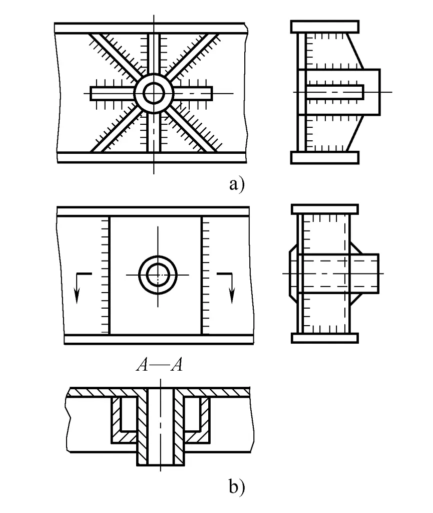
Using a reasonable welding structure, cleverly using profiles or pressed and formed sheet structures, minimizing welds not only reduces the welding workload and deformation but sometimes also improves production efficiency and reduces production costs. Figure 9-53a shows a traditional radial rib plate reinforced bearing structure, and Figure 9-53b shows a channel steel reinforced bearing structure, clearly, the structure of Figure 9-53b is much better than that of Figure 9-53a.
Selecting appropriate joint and groove forms can reduce welds, reduce welding workload and welding deformation. As shown in Figures 9-54 and 9-55, where Figures 9-54b and 9-55 have much smaller groove forms and weld sizes compared to Figures 9-54a and 9-55.
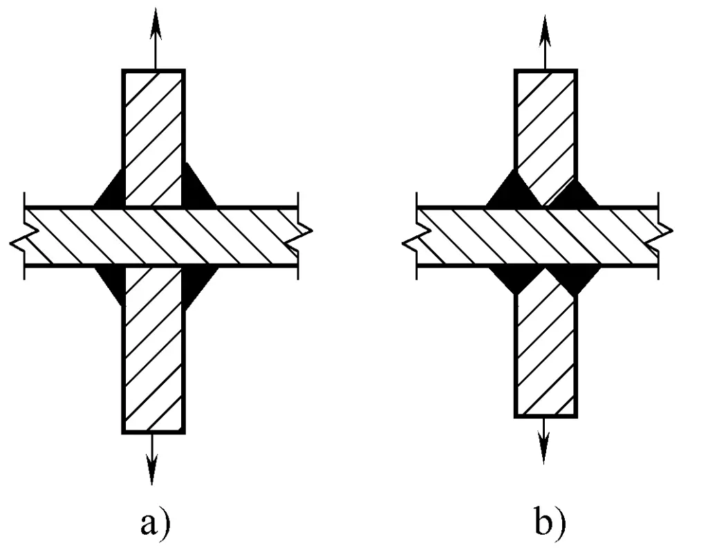
a) No groove
b) With groove
Under the premise of ensuring sufficient load capacity and weld quality, try to use the smallest possible weld size in terms of plate thickness to reduce the total amount of deposited metal, thereby reducing welding deformation.
As shown in Figure 9-56a, try to use shaped steel and stampings instead of welded parts to reduce the number of welds.
As long as the structure allows, the position of the welds should be as close as possible to the neutral axis of the component section and symmetrical to that central axis to reduce the bending deformation of the component, as shown in Figure 9-56b.
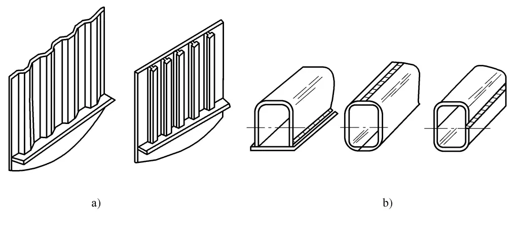
a) Reduce the number of welds to decrease welding deformation
b) Reasonably arrange the position of welds
For a beam that has significantly more welds on the top than on the bottom, the entire beam bends upwards after welding. For such a structure, the beam’s own weight can be used to prevent bending deformation. Before welding, place the beam on two closely spaced supports, first weld the bottom of the beam. Due to the bending caused by the beam’s own weight and the shrinkage of the weld, the bending of the beam increases, as shown in Figure 9-57.
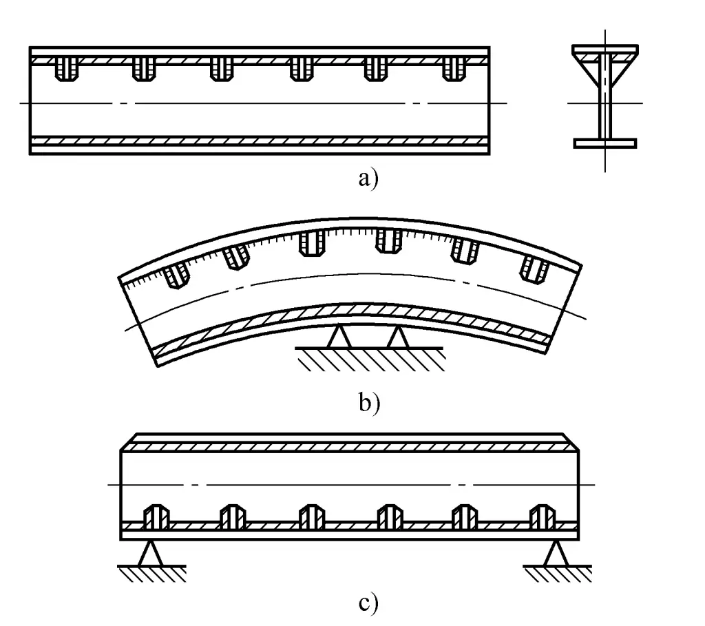
After the bottom of the beam is welded, place the supports at both ends, turn the beam over and then weld the top of the beam. Since the supports are placed at both ends of the beam, the beam’s self-weight bending deformation is opposite to the first one. Moreover, the shrinkage deformation direction of the upper weld is also opposite to that of the lower weld, resulting in a deformation that straightens the beam or leaves it with only a slight bend.
In actual production, use self-weight deformation combined with welding deformation to create the camber of the crane beam.
During the welding process, fixtures can be used to reduce deformation.
Correct and reasonable design is an important part of controlling deformation, but correct and reasonable design cannot completely control residual deformation. The correct process method is an important measure to control deformation.
When cutting material, increase the length or width dimensions of the parts slightly more than the design dimensions to compensate for the shrinkage of the weldment. The amount of allowance is determined based on the formula introduced earlier and combined with production experience. The allowance method is mainly used to prevent shrinkage deformation of the weldment.
For example: For crane beams (box beams), the required camber after welding is 9/1000~1.4/1000. When cutting the web plate, it is necessary to reserve the amount of shrinkage and deformation after welding. Generally, the camber during web plate cutting is 15/1000~18/1000. Thus, the reserved shrinkage and deformation can offset the shrinkage and deformation after welding. Generally, when cutting parts of components, add 0.3~1mm per meter, which is also intended to offset the shrinkage after welding.
Based on the pattern of deformation occurring in production, artificially create a deformation in the weldment beforehand that is opposite in direction but equal in magnitude to the deformation that occurs after welding, as a method to prevent residual deformation. This method is very effective, but it requires accurately estimating the direction and size of the deformation that may occur after welding, and flexibly applying it based on the structural characteristics of the weldment and production conditions.
1) Anti-deformation without external force.
When angular deformation occurs in butt welding of plates, the welding residual deformation can be controlled as shown in Figure 9-58a; when the transverse deformation at the end of electroslag welding is greater than at the start, the gap of the joint can be adjusted smaller at the bottom and larger at the top during installation and positioning, as shown in Figure 9-58b.
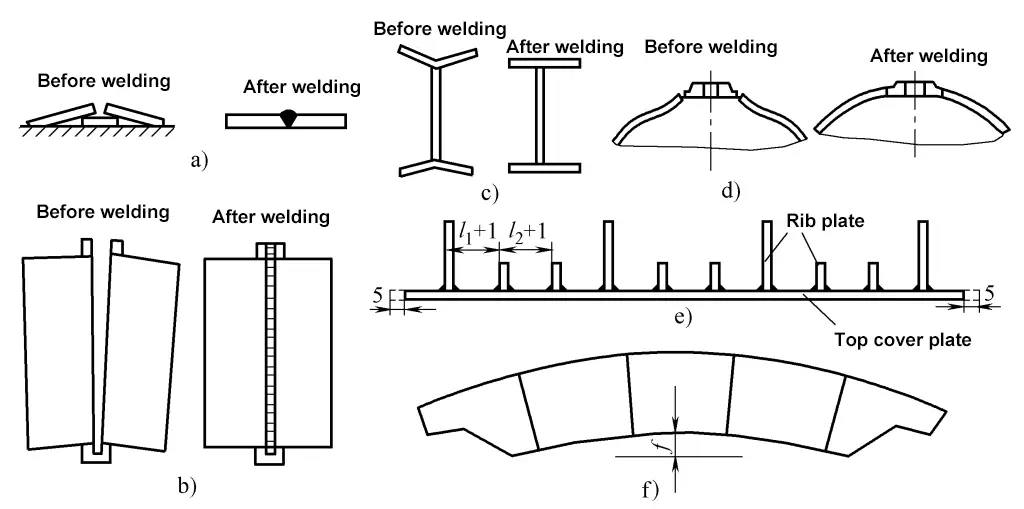
a) Plate butt welding
b) Electroslag butt vertical welding
c) Plastic pre-bending of space beam flanges
d) Shell anti-local collapse
e) Crane box beam top plate reserved for shrinkage allowance
f) Crane box beam web pre-arched
For T-joint welding, if angular deformation occurs in the flat plate after welding, the plate can be pre-bent in the opposite direction before welding, as shown in Figure 9-58c; for thin-walled shells butt welded from the outside on one side with a flange, if inward concave deformation occurs, pre-bending the edge outward before welding can be done, as shown in Figure 9-58d.
Leaving a shrinkage allowance is essentially also a counter-deformation. For example, in the case of a box girder of a bridge crane, when the top cover plate is welded to the rib plates as shown in Figure 9-58e, if each rib plate’s corner weld shrinks by 0.5mm and there are 20 corner welds, a 10mm allowance must be reserved in the length of the top cover plate during material preparation, and distributed evenly among the rib plates.
To overcome the deflection deformation caused by the post-processing of this box girder, a pre-fabricated camber f as shown in Figure 9-58f is created during the fabrication of the web plate, which is greater than the camber during the final product acceptance.
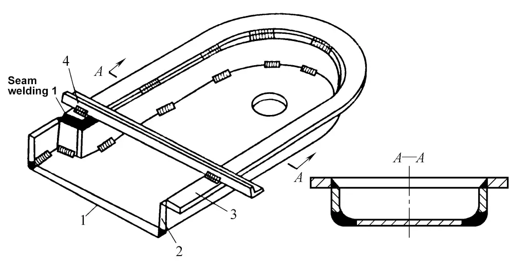
Figure 9-59 shows the counter-deformation welding device and its welding sequence for the boiler steam drum. Two welders weld a row of tube seats each on the same steam drum, following the skip welding sequence shown in Figure 9-59c. After welding two rows of tube seats on one steam drum, the same method is used to weld the tube seats on another steam drum, alternating until all welding is complete, which significantly prevents deformation after welding.
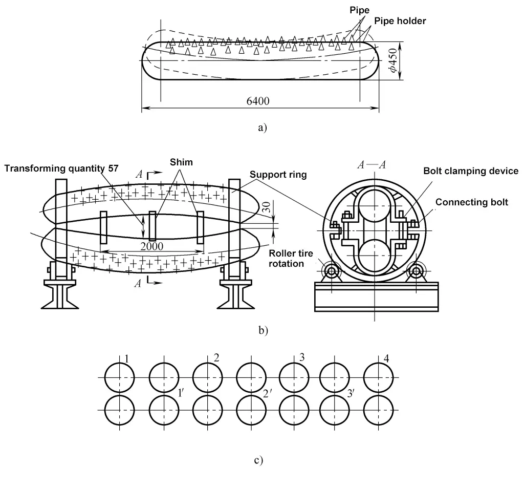
a) Deformation of the steam drum after welding without using counter-deformation method.
b) Counter-deformation welding flip mold for the steam drum.
c) Skip welding sequence for the tube seats.
2) Counter-deformation under external force.
Use welding molds or fixtures to weld the workpiece under counter-deformation conditions. After welding, release the mold or fixture, and the workpiece will spring back to exactly meet the technical requirements in terms of shape and size.
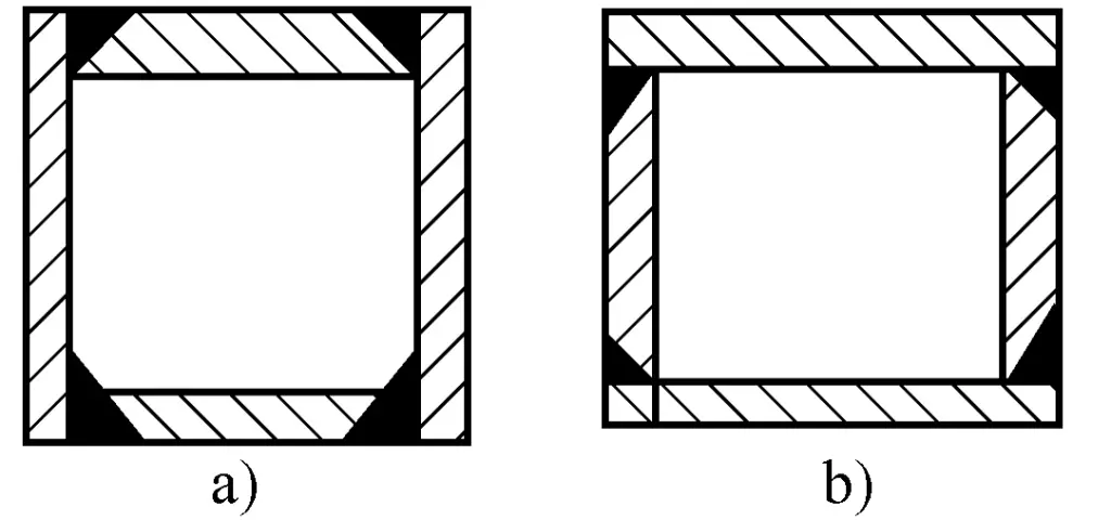
Figure 9-60 shows the use of simple fixtures to counter-deform a flat plate to overcome angular deformation caused by welding of I-beams; Figures 9-61a, b, c, d show hollow components that will bend after welding due to the concentration of welds on the upper side.
As shown in Figure 9-61e, use the turning jig to make two components with the same cross-section “back to back”, clamping the ends and raising the middle, thus each component is welded in a reverse bending situation. This turning jig facilitates welding and also improves production efficiency.
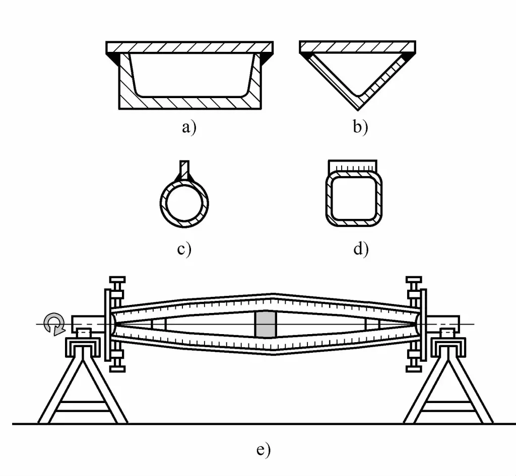
a), b), c) Hollow beams with a single-sided longitudinal weld
d) Hollow beams with a single-sided transverse weld
e) Welding on the welding turning jig
The following two issues must be considered when using the external force anti-deformation method.
① Safety issues. The required external force should be sufficiently large, therefore, the used jig must ensure strength and rigidity. The workpiece is in an elastic state during anti-deformation and remains elastic after welding. When the clamp is released, the workpiece will inevitably spring back, and it is essential to prevent injuries from this rebound.
② The most reliable method to control the amount of anti-deformation is to use standard welding parameters to perform a trial weld in a free state and measure the residual deformation. This deformation should be used as the basis for the anti-deformation, combined with the rebound of the workpiece, make appropriate adjustments so that the shape and size of the workpiece after rebounding exactly match the technical requirements of the workpiece.
3) Pre-stretching method for thin plate welding.
This is an example of flexibly applying the counter-deformation method in thin-walled welded structures to prevent post-welding wavy deformation of the back panel. A frame made of profiled surfaces is welded on the inside of the thin-walled flat plate, and after welding, the peripheral weld shrinkage causes the thin plate within the frame to generate compressive stress reaching or exceeding its buckling critical stress, resulting in wavy deformation, as shown in Figure 9-62.
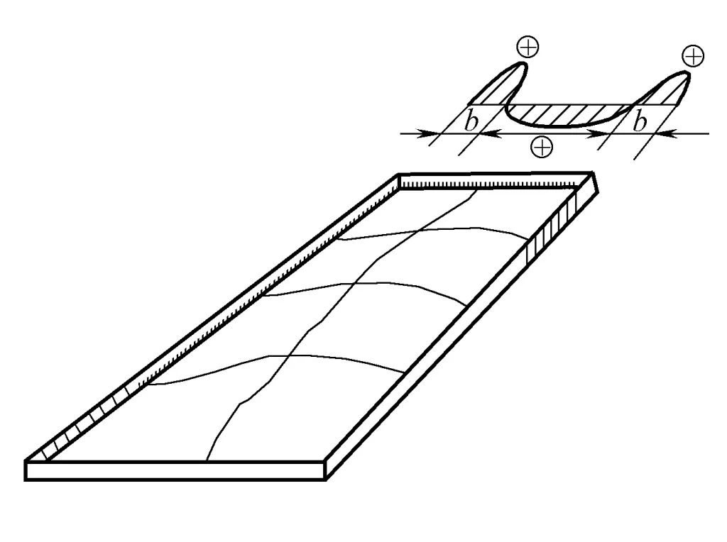
If pre-stretching by mechanical pre-stretching, heated pre-stretching, or a combination of both methods is applied in areas likely to shorten, and then formally assembled and welded with the frame, and the pre-stretching heat is removed after welding, the thin-walled plate can return to its initial state, effectively reducing residual stress and achieving the purpose of preventing wavy deformation of the wall plate.
Table 9-12 shows three implementation schemes: stretching method (SS method), heating method (SH method), and a combination of both (SSH method). The stretching method requires a specially designed mechanical device; the heating method can use current through the wall plate, relying on its own resistance to directly heat instead of indirect heating by heaters.
Table 9-12 Implementation schemes for controlling unstable deformation of thin-walled plate welding by pre-stretching method
| No. | Methods | Schematic diagram | |
| 1 | SS method Stretching method | 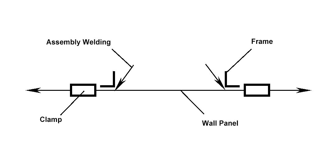 | 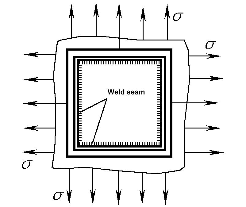 |
| 2 | SH method Heating method | 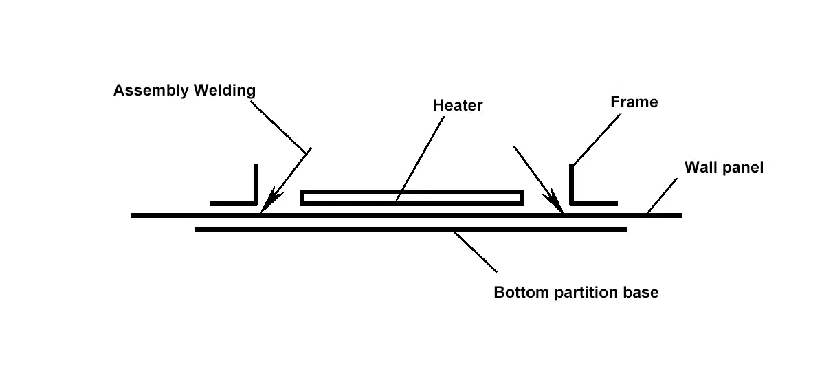 | 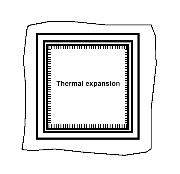 |
| 3 | SSH method Stretching method + Heating method | 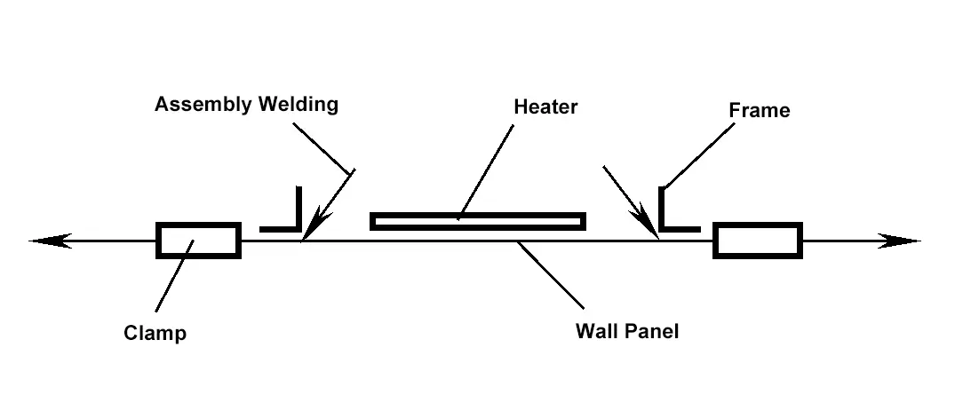 | 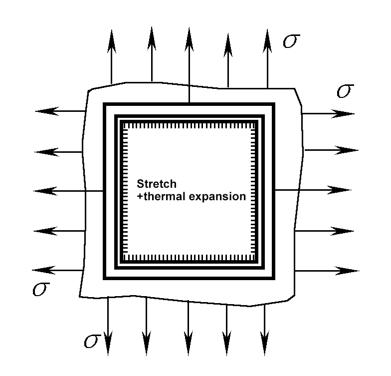 |
By using appropriate methods to increase the rigidity and restraint of the weldment, the purpose of reducing its deformation can be achieved, which is the rigid fixation method. Common rigid fixation methods include the following:
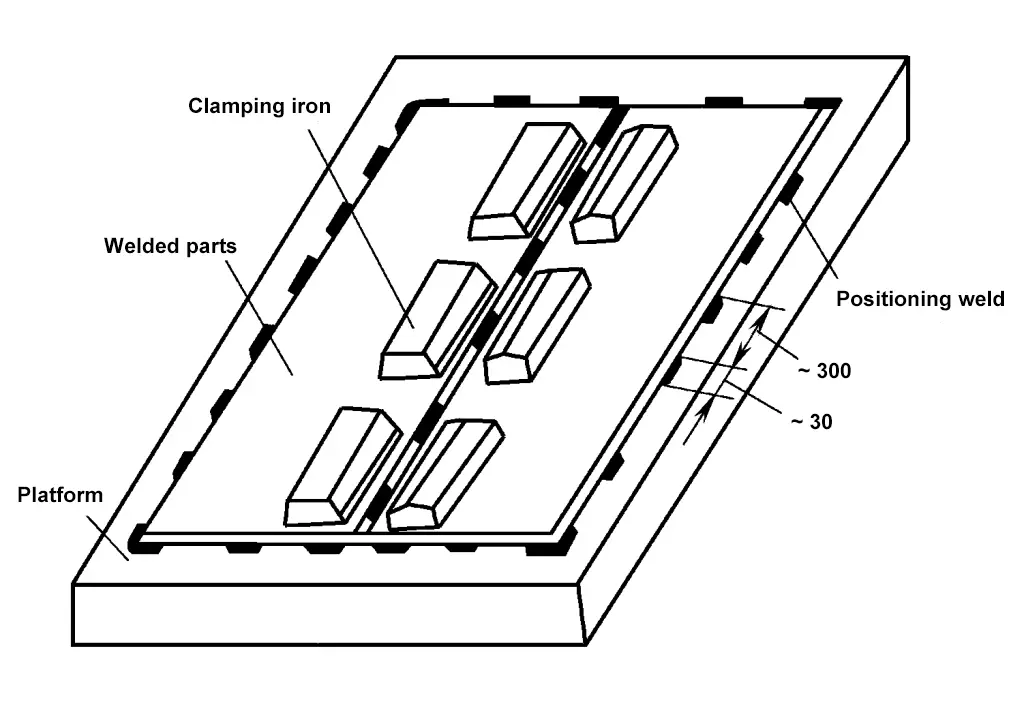
1) Fix the weldment on a rigid platform.
When welding thin plates, they can be fixed on a rigid platform with positioning welds, and the welds near the back can be pressed down with a press iron, as shown in Figure 9-63. After all the welds are completely welded and cooled, the positioning welds are then removed, which can avoid wave deformation during thin plate welding.
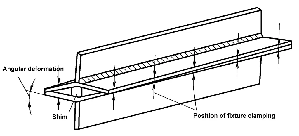
2) Combine the weldments into a structure with greater rigidity or symmetry.
When welding T-beams, it is easy to produce angular deformation and bending deformation. Figure 9-64 shows two T-beams combined together, making the weld seam symmetrical to the neutral axis of the structural section, which greatly increases the stiffness of the structure, and uses the counter-deformation method (shims are used in Figure 9-64), adopting a reasonable welding sequence, which is beneficial to prevent bending deformation and angular deformation.
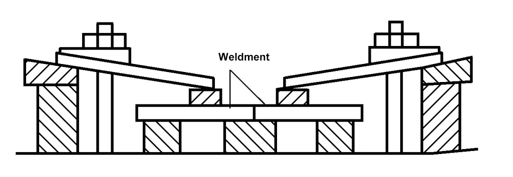
3) Use welding fixtures to increase the stiffness and restraint of the structure.
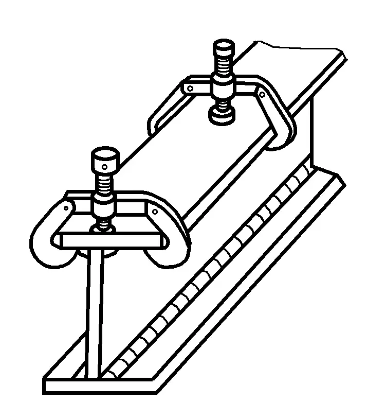
Figure 9-65 shows the use of clamps to fix the weldment, to increase the restraint of the component, and to prevent angular deformation and bending deformation of the component.
4) Use temporary supports to increase the restraint of the structure.
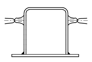
In single-piece production, using specialized fixtures is not economically reasonable. Welding some temporary supports or tie rods on parts prone to deformation can increase local stiffness and effectively reduce welding deformation. Figure 9-66 is an application example of using temporary supports on a protective cover to increase restraint.
1—Base plate
2—Vertical plate
3—Flange plate
4—Temporary support
The assembly and welding sequence has a significant impact on the deformation of the welded structure, therefore, a reasonable assembly and welding sequence can be used to control welding deformation. To control and reduce welding deformation, the selection of the assembly and welding sequence should follow these principles:
1) The weld being welded should be as close as possible to the neutral axis of the structural section.
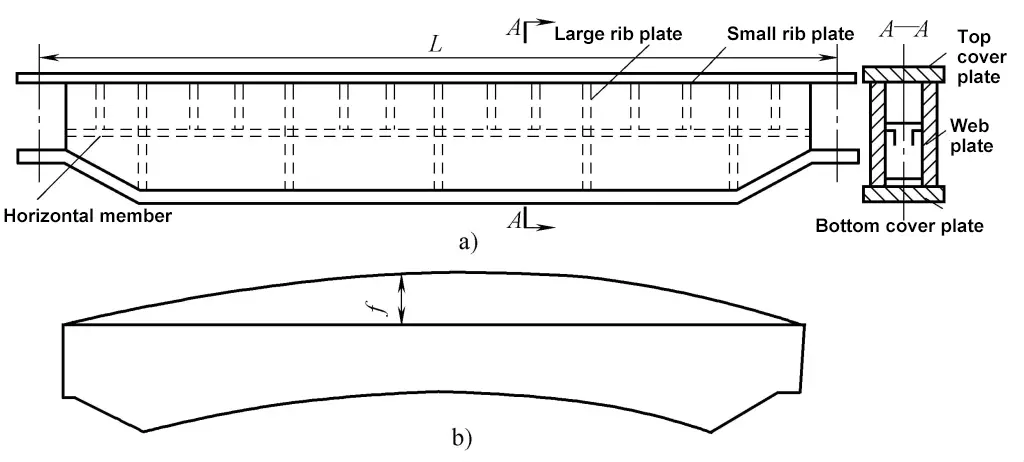
As shown in Figure 9-67a, the main beam structure of the bridge crane requires a certain upward camber. To achieve this requirement, in addition to prefabricating the upward camber of the left and right web plates, the best assembly and welding sequence should be selected to minimize the downward bending deformation.
2) For structures with asymmetrically arranged welds, weld the side with fewer welds first during assembly and welding.
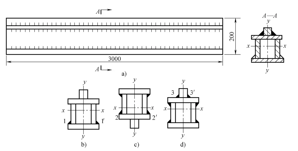
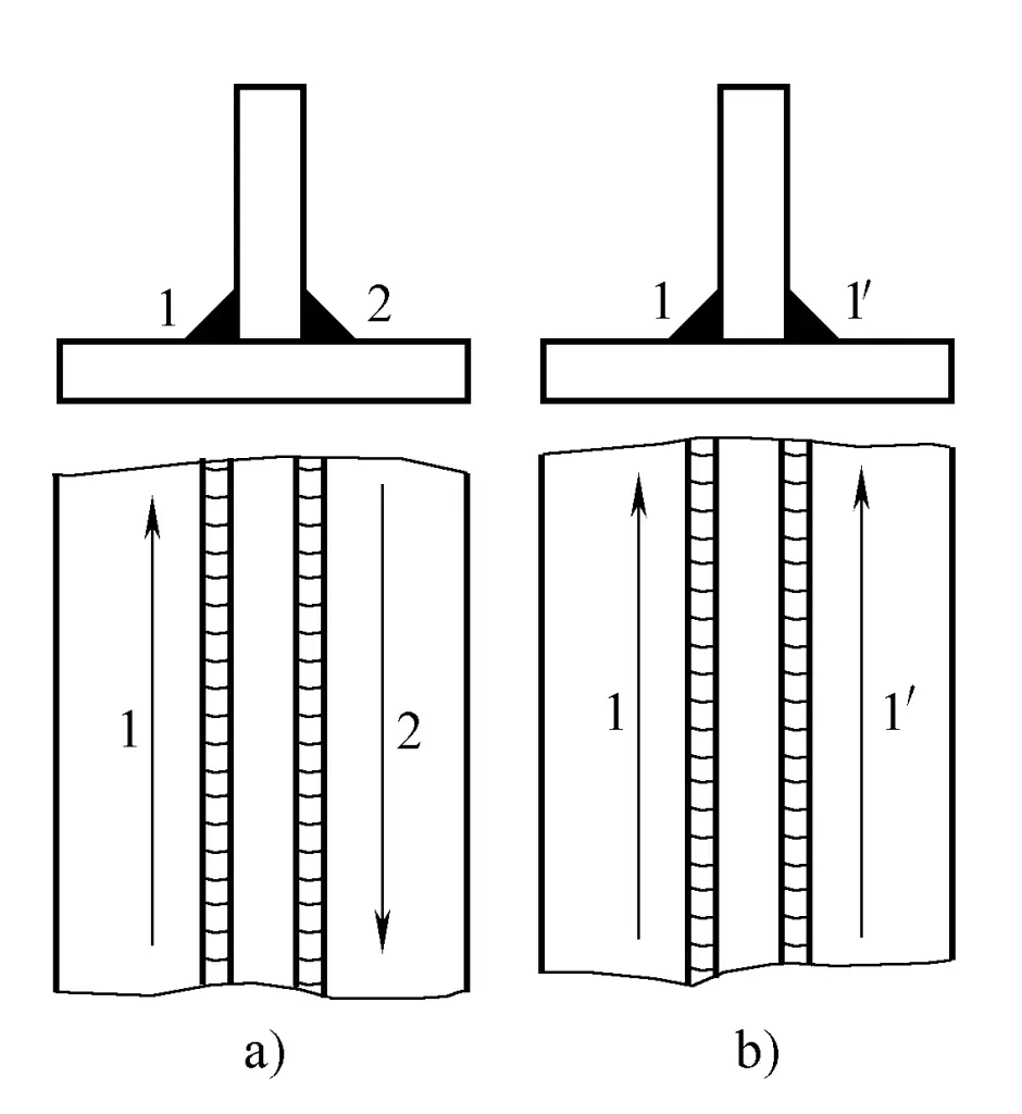
As shown in Figure 9-68, the upper die section of the press has more welds above the neutral axis than below it. If the assembly and welding sequence is unreasonable, it will ultimately produce downward bending deformation.
The solution is to first symmetrically weld seams 1 and 1’ (see Figure 9-68b), which will produce a significant upward camber bending deformation f 1 and increase the stiffness of the structure; then weld seams 2 and 2’ at the position shown in Figure 9-68c, producing downward bending deformation f 2 ; finally, weld seams 3 and 3’ at the position shown in Figure 9-68d, producing downward bending deformation f 3 . This makes f 1 approximately equal to f 2 , and the sum of f 3 , and the directions are opposite, so the bending deformations can essentially cancel each other out.
3) For structures with symmetrically arranged welds, an even number of welders should weld symmetrically.
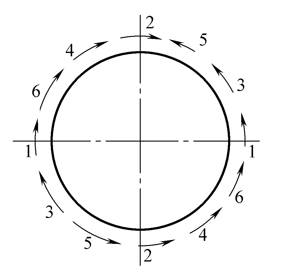
As shown in Figure 9-69, the butt weld of the cylindrical body is best welded symmetrically by two welders.
4) Long welds (over 1m) can be welded in the direction and sequence shown in Figure 9-70 to reduce post-weld shrinkage deformation.
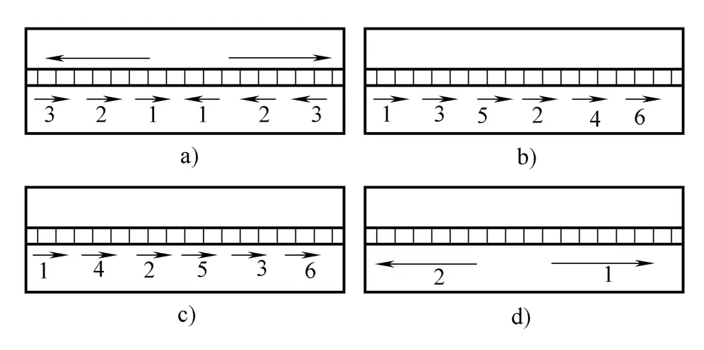
5) To prevent distortion, adjacent welds should be welded in the direction and sequence shown in Figure 9-71b.
a) Incorrect
b) Correct
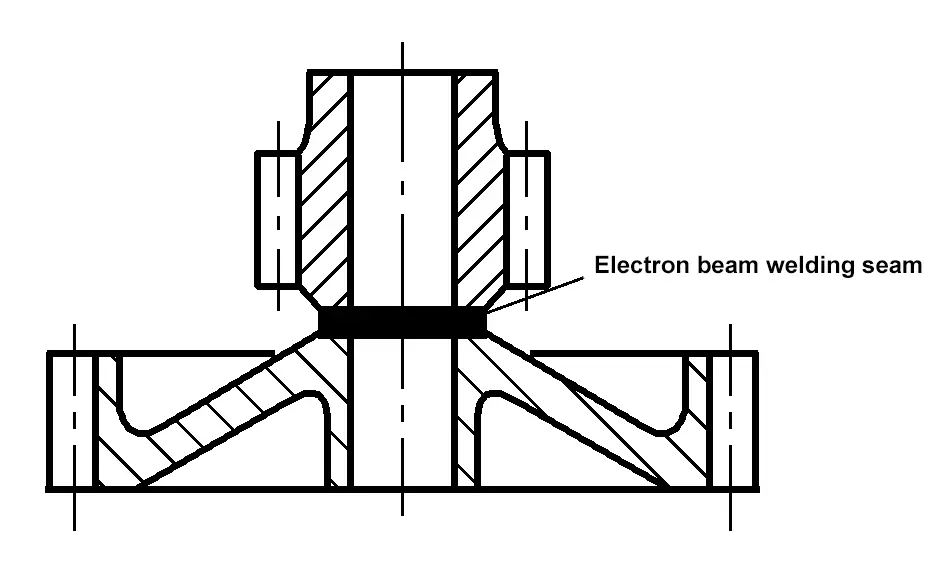
Different welding methods have different heat inputs, thus causing different deformations. Using welding methods with more concentrated energy can reduce welding deformation. For example, use CO 2 gas shielded welding or plasma arc welding instead of gas welding and shielded metal arc welding for thin plate welding; use vacuum electron beam welding for precision machined products, such as gears (see Figure 9-72), to control their deformation.
Different welding parameters are used for different parts of the same structure. This can achieve the purpose of controlling and adjusting welding deformation. As shown in Figure 9-73, the asymmetric section beam, because the distance s from welds 1, 2 to the neutral axis of the structure section is greater than the distance s’ from welds 3, 4 to the neutral axis, bending deformation occurs downwards after welding.
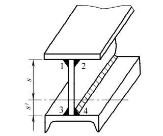
1 ~ 4—Weld seam
If multi-layer welding is used for welds 1 and 2, choosing smaller heat input for each layer; and single-layer welding is used for welds 3 and 4, choosing larger heat input, then the downward deformation produced by welding welds 1 and 2 can basically offset the upward arching deformation produced by welding welds 3 and 4, resulting in a basically flat structure after welding.
For some structures with asymmetrically arranged welds, bending deformation often occurs after welding. If gas flame heating is used in a position symmetrical to the welds and synchronized with the welding, as long as the heating process parameters are chosen appropriately, it can reduce or prevent bending deformation of the component. As shown in Figure 9-74, the thermal balancing method is used to control the welding deformation of a side beam box structure.
The cooling method involves using various ways to quickly dissipate heat from the welding area, such as using direct water cooling and copper cooling blocks to limit and reduce the distribution of the welding heat field, in order to reduce welding deformation. Note, use caution with materials that have high hardenability.
In the actual production process of welded structures, various deformations should be fully estimated, the patterns of various deformations analyzed, and one or several methods selected based on site conditions to effectively control welding deformation.