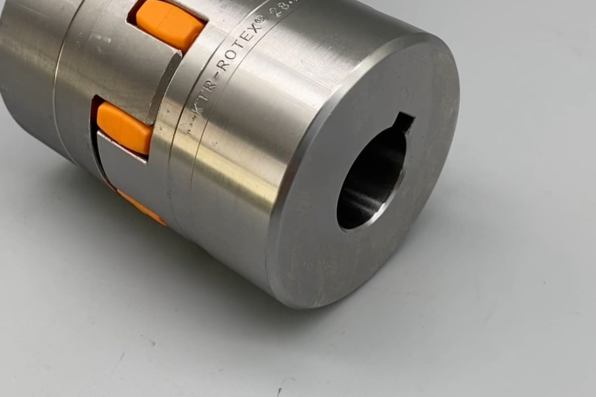
There are many types of couplings. According to whether they contain elastic elements inside, they can be divided into elastic couplings and rigid couplings. Rigid couplings are further divided into fixed rigid couplings and movable rigid couplings based on their structural characteristics.
Due to the structural requirements of the machine, manufacturing and installation errors, changes in working temperature, and deformation after loading, the two shafts connected by the coupling often cannot be guaranteed to be aligned, resulting in relative displacement within a certain range, as shown in Figure 1.

a) Axial displacement
b) Radial displacement
c) Angular displacement
d) Comprehensive displacement
If these displacements are not compensated, additional loads will be generated on the coupling, shafts, and bearings, and may even cause severe vibrations. Therefore, these factors must be comprehensively considered when selecting the type of coupling.
I. Characteristics and Applications of Common Couplings
1. Fixed Rigid Coupling
This type of coupling has a simple structure, low cost, no compensation performance, cannot buffer and reduce vibration, and requires high installation accuracy for the two shafts. This type of coupling is often used in conditions with very little vibration, connecting two shafts with medium to high speed and low rigidity that require high alignment. The characteristics and applications of commonly used fixed rigid couplings are shown in Table 1.
Table 1 Types, Characteristics, and Applications of Common Fixed Rigid Couplings
Flange Coupling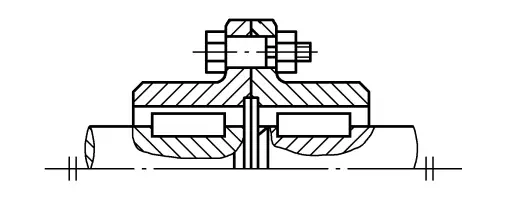 GY Type 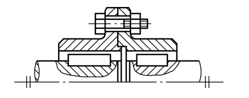 GYS Type Easy to use and maintain, good rigidity, and high load capacity. When the alignment accuracy of the two shafts is not high, the additional dynamic load is large. When manufactured with high precision, it can be used for high-speed transmission. There are two forms: GY type (connected and aligned with reamed bolts) and GYS type (connected with ordinary bolts and aligned with the convex and concave surfaces of the half-coupling end face). | Sleeve Coupling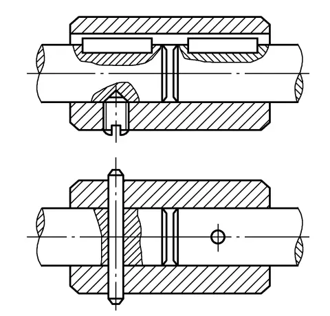 Small radial size, requires a large axial movement distance during assembly and disassembly, suitable for occasions where the two shafts can be strictly aligned, the load is not large and relatively stable, and the coupling requires a small radial size. Additionally, it can be used as a safety coupling. |
2. Movable Rigid Coupling
This type of coupling uses its own relatively movable elements or gaps to allow a certain relative displacement between the connected two shafts, providing some displacement compensation capability. Its characteristics and applications are shown in Table 2.
Table 2 Types, Characteristics, and Applications of Common Movable Rigid Couplings
Gear Coupling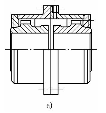 High load capacity, reliable operation, with a small amount of comprehensive displacement compensation capability, low installation accuracy requirements, but complex structure, high manufacturing cost, noise, and cannot buffer and reduce vibration. Suitable for heavy machinery with frequent starting and frequent forward/reverse operations. | Cross-Slider Coupling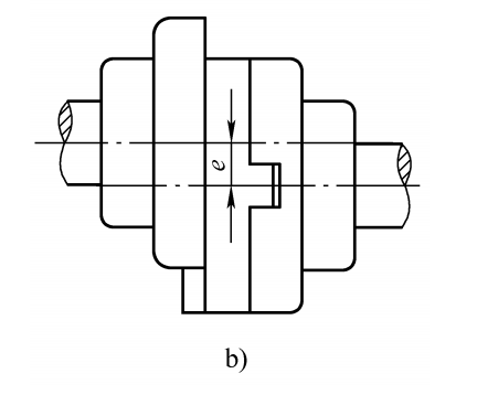 Simple structure, small radial size, can compensate for radial and angular displacement. Mainly used in occasions with stable operation, low speed, high torque, and small impact. |
Universal Coupling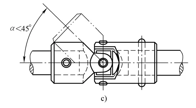 Small radial size, compact structure. Mainly used for transmission with a large angle between two shafts (α<45°) or large angular displacement during operation. To prevent additional dynamic loads, they are often used in pairs. | 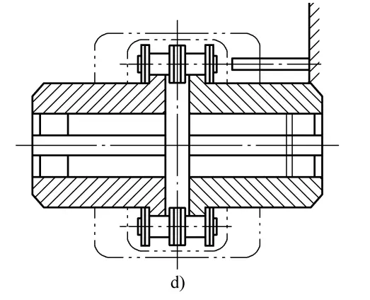 Simple structure, lightweight, reliable operation, easy assembly and disassembly, with a small amount of compensation for the relative displacement of the two shafts. Used in humid, dusty, and high-temperature environments, not suitable for frequent starting, frequent forward/reverse operations, and severe impact loads and torsional vibration occasions. |
3. Elastic Coupling
This type of coupling is equipped with elastic elements, which not only can compensate for the relative displacement between the two shafts but also have buffering and vibration absorption functions. The materials of the elastic elements include non-metal (rubber, plastic, etc.) and metal (spring steel).
The former is lightweight and has strong buffering and vibration absorption capabilities, simple structure, and insulation properties, but attention should be paid to controlling the working temperature and avoiding exposure to sunlight, rain, and contact with oils, acids, alkalis, and organic solvents; the latter has high strength and long life but is costly. Currently, elastic couplings are widely used, and their application characteristics are shown in Table 3.
Table 3 Types, Characteristics, and Applications of Elastic Flexible Couplings
Elastic Sleeve Pin Coupling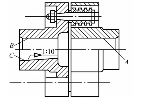 Simple structure, easy to assemble and disassemble, with a certain ability to compensate for the relative displacement between shafts, can buffer and absorb vibrations, working temperature is -20 to +70℃. Used for medium and high-speed transmission with frequent starting and reversing of medium and small torque. | Elastic Pin Coupling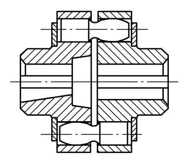 Simple structure, easy to manufacture and maintain, working temperature is -20 to +70℃. Suitable for medium and low-speed transmission with frequent starting and reversing of larger torque. |
Tire Coupling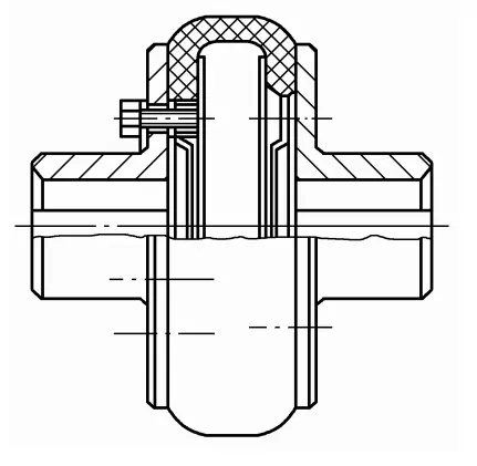 Simple structure, reliable operation, good comprehensive displacement compensation ability, strong vibration reduction. Working temperature is -20 to +80℃. Suitable for humid and dusty environments, frequent starting and reversing, and large impact occasions, with an outer edge speed not exceeding 30m/s, widely used in lifting machinery. | Diaphragm Coupling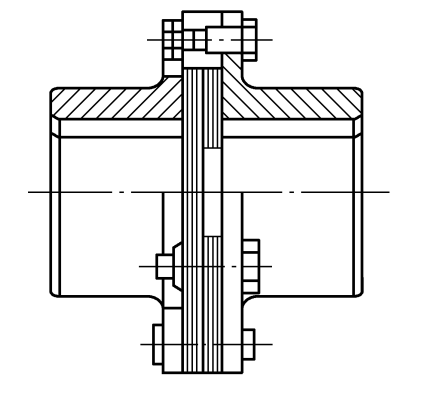 Compact structure, high strength, long service life, with characteristics of acid, alkali, and corrosion resistance, and no need for lubrication. Can be used in high temperature, high speed, and corrosive media conditions, widely used in various mechanical transmissions, working temperature -20 to +250℃. |
II. Selection of Couplings
The selection of coupling types should focus on the following aspects:
- The size and nature of the load;
- The speed of the shaft;
- The size and nature of the relative displacement between the two shafts;
- The working environment and allowable space, etc.
For example, for low-speed shafts with stable loads, if the shaft rigidity is high and alignment is strict, a fixed rigid coupling can be selected according to Table 1; if the shaft rigidity is low and there is relative displacement, a movable rigid coupling can be selected according to Table 2; for high-speed shafts with large impact and vibration and relative displacement, a movable elastic coupling can be selected according to Table 3; for two shafts with large angular displacement, a universal coupling should be selected. For shafts with large dynamic loads and very high speeds, a lightweight coupling with low rotational inertia should be selected.
After selecting the type of coupling, the calculated torque Tc of the coupling can be obtained, and the appropriate coupling model can be selected from the standard based on the shaft diameter, calculated torque, and speed.
Example 16-1 Selection of the coupling between the motor and the reducer in a sand mixer. Given the motor rated power P=15kW, full load speed n=1460r/min, motor shaft diameter d 1 =42mm, reducer input shaft diameter d 2 =40mm.
Solution:
1. Select the type of coupling
Considering the high speed of the shaft, moderate torque, frequent starting, and the general relative displacement between the motor and the reducer shafts, an elastic sleeve pin coupling is selected according to Table 3.
2. Select the coupling model
(1) Calculate the torque Tc
The torque variation of the sand mixer is moderate, check the working condition coefficient, take K=1.7, thus
Tc=KT=1.7×9550P/n=1.7×9550×15/1460N·m=166.8N·m
(2) Select the model
According to GB/T 4323—2002, the coupling model is selected as LT6 (the half-coupling material is steel), according to GB/T 4323—2002:
- The nominal torque Tn =250N·m>Tc ;
- The allowable speed [n]=3800r/min>n, suitable.
The motor shaft end half-coupling uses a Y-type shaft hole, shaft hole diameter d1 =42mm, shaft hole length L=112mm; the reducer shaft end half-coupling uses a J1 type shaft hole, shaft hole diameter d2 =40mm, shaft hole length L1 =84mm. The coupling mark is:
LT6 Coupling (Y42×112)/(J 1 40×84) GB/T 4323—2002

