Understanding the Current Carrying Capacity of Copper Conductors
Have you ever wondered why certain electrical wires are thicker than others, or why copper is often the metal of…
Have you ever wondered why copper cables are the backbone of electrical installations, or how their current carrying capacity is determined? In this technical reference guide, we delve deep into understanding the current carrying capacity of copper cables, a critical factor in ensuring safe and efficient electrical systems. From defining what current carrying capacity entails to exploring the advantages of copper conductors, this article will provide you with a comprehensive overview tailored for intermediate-level readers. We’ll dissect NEC Table 310.15(B)(16), explain AWG sizing, and offer practical insights into ampacity charts. Curious about the factors affecting current carrying capacity or how conductor size relates to power capacity? Read on as we explore these topics and more, ensuring you leave with a solid grasp of copper cable sizing and its practical applications.
Current carrying capacity, also known as ampacity, is the highest amount of electric current a conductor can safely handle before it overheats. This parameter is critical in electrical installations to prevent overheating, which can lead to insulation damage, conductor failure, or fire hazards. Ampacity is determined by various factors, including the conductor’s material, size, insulation type, installation conditions, and ambient temperature.
Understanding and correctly determining the current carrying capacity of conductors is crucial for designing safe and efficient electrical systems, as it ensures wires and cables can handle the expected load without overheating. Proper ampacity prevents electrical fires and ensures the longevity of the installation. Engineers and electricians must consider ampacity to comply with electrical codes and standards, such as the National Electrical Code (NEC), which provides guidelines for safe electrical practices.
The material of the conductor significantly influences its ampacity. Copper is a preferred choice for electrical wiring because it has high electrical conductivity and low resistivity. The purity and temperature of the copper also affect its resistivity, impacting the current carrying capacity.
The cross-sectional area of a conductor is directly proportional to its ampacity. Larger cross-sectional areas reduce electrical resistance and heat generation, allowing higher currents to flow safely. This is why thicker wires can carry more current than thinner ones.
The construction and type of the cable, including the number of cores and the type of insulation, play a crucial role in determining ampacity. For example, multi-core cables might have different ampacity ratings compared to single-core cables with the same cross-sectional area due to variations in heat dissipation.
The conditions under which a cable is installed affect its ability to dissipate heat. Factors such as whether the cable is laid on walls, buried underground, or bundled with other cables can significantly impact its current carrying capacity. Poor ventilation or enclosures can reduce cooling efficiency, thus lowering ampacity.
Ambient temperature has a direct impact on the current carrying capacity of a conductor. Higher ambient temperatures reduce the conductor’s ability to dissipate heat, thereby lowering its ampacity. Electrical codes often provide correction factors to adjust ampacity based on ambient temperature variations.
Alternating current (AC) effects, such as the skin effect, and the power factor (cos φ) influence the actual current that can be safely carried by a conductor. These factors must be considered, especially in high-frequency AC applications.
For three-phase AC systems, the ampacity can be estimated using the following formula, which adjusts theoretical capacity for practical installation conditions and electrical parameters:
Where:
Standards like DIN VDE 0298-4 provide typical maximum current ratings for copper conductors under standard installation conditions, ensuring compliance and safety. For instance, at 230 V AC:
| Cross-Section (mm²) | Installation Type | Maximum Current (A) |
|---|---|---|
| 1.5 | Two loaded cores on wall | 19.5 |
| 2.5 | Two loaded cores on wall | 27 |
These values are based on standard insulation and typical ambient conditions.
Choosing the correct cable size is vital to avoid overheating and ensure reliability. Oversizing cables can lead to increased costs and installation complexity, while undersizing can risk failures and hazards. Engineers must carefully consider the installation environment, load characteristics, and applicable standards when determining the current carrying capacity to ensure safe and efficient electrical systems.
Copper conductors are widely recognized for their exceptional properties, making them the preferred material for electrical wiring in various applications.
Copper boasts the highest electrical conductivity of all non-precious metals. This property is crucial for efficient electrical power transmission, as it minimizes resistive losses. The International Annealed Copper Standard (IACS) rates copper’s conductivity at 100% IACS, equivalent to 58.0 MS/m. Modern commercial copper often exceeds this standard, ensuring optimal performance in electrical systems.
Copper’s thermal conductivity is significantly higher than that of other commonly used materials, such as aluminum. This property enables copper conductors to efficiently dissipate heat, significantly lowering the risk of overheating. Efficient heat dissipation is vital for maintaining the integrity of electrical connections and preventing thermal damage to insulation.
Copper exhibits excellent mechanical properties, including high ductility and tensile strength. Its malleability makes it easy to bend and shape, perfect for tight installations. Additionally, copper’s tensile strength ensures durability and resistance to mechanical stress, which is particularly important in industrial applications where cables may be subject to physical strain.
Copper conductors offer several advantages over other materials commonly used in electrical wiring, such as aluminum.
Thanks to copper’s superior conductivity, smaller diameter wires can handle the same current as larger aluminum ones. This results in reduced insulation and conduit requirements, simplifying installation and reducing overall costs.
Unlike aluminum, which forms a non-conductive oxide layer, copper oxide remains conductive. This property eliminates the need for anti-oxidant compounds at connections, ensuring reliable electrical performance and reducing maintenance requirements.
Copper’s inherent corrosion resistance ensures long-term reliability, even in humid or chemically aggressive environments. This makes copper conductors suitable for a wide range of applications, from residential wiring to industrial installations.
Copper conductors are characterized by several key performance metrics that influence their suitability for different applications.
Copper’s resistivity increases with temperature, affecting its current carrying capacity. The conductivity of copper decreases by approximately 0.393% per degree Celsius above 20°C. This necessitates derating in high-temperature environments to ensure safe operation.
Copper conductors provide a higher current density per square millimeter compared to aluminum. This translates to more efficient energy transmission over long distances, reducing power losses and improving overall system efficiency.
Copper conductors comply with various industry standards, ensuring their suitability for diverse applications.
Copper wires used in building and industrial applications often achieve conductivity levels greater than 100% IACS due to advanced refining techniques. This ensures adherence to stringent performance requirements and enhances the reliability of electrical systems.
The smaller diameter of copper conductors allows more wires to be installed within a given conduit size. This simplifies retrofits and expansions, providing greater flexibility in electrical system design and installation.
Copper’s corrosion resistance makes it an ideal choice for environments where humidity or chemical exposure is a concern. This durability ensures the longevity of installations and reduces the need for frequent replacements.
Recent advancements in copper conductor technology emphasize sustainable refining and alloy improvements to enhance conductivity and mechanical strength. These developments aim to reduce lifecycle costs and improve recyclability, aligning with global trends towards sustainable electrification.
When designing electrical systems, several practical considerations must be taken into account to leverage the benefits of copper conductors.
Using tables from standards like NEC or IEC, designers can match the ampacity of copper conductors with thermal limits to ensure safe operation. Proper sizing is critical to prevent overheating and maintain system reliability.
Copper’s compatibility with oxide layers ensures reliable, low-maintenance connections. This property is particularly important for terminations and splices, where electrical integrity must be maintained over time.
Despite a higher initial cost compared to aluminum, copper’s efficiency and longevity result in lower total ownership costs. This makes copper conductors a cost-effective choice for both residential and industrial applications.
Sources: Industry standards (IACS), technical reports (CuSP, Copper.org), material science analyses.
NEC Table 310.15(B)(16) is an essential guide in the National Electrical Code (NEC) that specifies the maximum current capacity for insulated conductors up to 2000 volts. This table is crucial for electrical engineers and technicians to ensure electrical systems are designed and installed safely, adhering to established standards.
NFPA70, commonly known as the National Electrical Code (NEC), provides comprehensive regulations for safe electrical design, installation, and inspection to protect individuals and property from electrical hazards. Table 310.15(B)(16) is a key component of these guidelines, offering detailed ampacity ratings for various conductor types and insulation materials.
The table categorizes ampacities based on the temperature rating of the conductor insulation, with common ratings being:
Different insulation types have distinct thermal and chemical properties, impacting their ampacity. Common insulation types listed in the table include:
Each insulation type has specific applications and environmental suitability, influencing the maximum current a conductor can handle without exceeding safe temperature limits.
The table is based on a surrounding temperature of 30°C (86°F) for its current capacity calculations. If the surrounding temperature differs, adjustments must be made using correction factors to ensure accurate ampacity values.
Ampacity values in the table assume no more than three current-carrying conductors in a raceway, cable, or buried in the earth. If more than three conductors are installed in a raceway, the current capacity must be reduced following NEC guidelines.
To use Table 310.15(B)(16), identify the conductor’s American Wire Gauge (AWG) size and its insulation temperature rating. This information provides the baseline ampacity, which may need adjustment based on installation conditions.
For instance, a 14 AWG copper conductor with THHN insulation at 75°C (167°F) typically has an ampacity of 20 amps. If more than three conductors are installed in a raceway, the current capacity must be reduced following NEC guidelines.
NEC mandates that overcurrent protection devices, such as circuit breakers or fuses, must not exceed the ampacity of the conductors they protect. For a 14 AWG copper conductor, a 15-amp breaker is generally appropriate to ensure compliance and safety.
When conductors are bundled or placed in raceways with more than three current-carrying conductors for distances over 24 inches, ampacity must be reduced according to NEC Table 310.15(B)(3)(a).
Surrounding temperatures different from 30°C (86°F) require adjustments to the ampacity values. Higher surrounding temperatures decrease the conductor’s ampacity.
The insulation type affects ampacity due to varying thermal resistance and durability. Selecting the appropriate insulation based on the installation environment is critical for maintaining safe and efficient electrical systems.
American Wire Gauge (AWG) is a standardized system used to measure the diameter and cross-sectional area of round, solid, nonferrous electrically conducting wire, primarily copper. The AWG system is logarithmic, meaning as the AWG number increases, the wire diameter decreases. This system provides a consistent and precise method for specifying wire sizes, which is essential for ensuring electrical safety and efficiency.
The size of a wire, as defined by its AWG rating, directly influences its current carrying capacity, also known as ampacity. Here are key points about how AWG sizing impacts current carrying capacity:
Understanding the conversion between AWG and square millimeters (mm²) is important for international applications and standard compliance. To convert from AWG to mm², use conversion tables or formulas. For example, a 10 AWG wire is about 5.26 mm². Conversely, to find the nearest AWG size for a wire with a given mm², use the same tables or formulas.
Choosing the correct AWG size is crucial for safety, performance, and regulatory compliance:
| AWG Size | Diameter (inches) | Diameter (mm) | Cross-Sectional Area (mm²) | Typical Max Current (Amps) |
|---|---|---|---|---|
| 12 | 0.0808 | 2.05 | 3.31 | ~20 |
| 8 | 0.1285 | 3.26 | 8.37 | ~50 |
| 4 | 0.2043 | 5.19 | 21.15 | ~95 |
| 1/0 (0) | 0.3249 | 8.25 | 53.49 | ~150 |
| 4/0 (0000) | 0.4600 | 11.68 | 107.22 | ~230+ |
(Values are approximate and depend on insulation, temperature rating, and installation conditions.)
This technical overview of AWG sizing underscores the critical relationship between wire gauge, physical dimensions, and current carrying capacity for copper conductors. Proper understanding and application of AWG standards are essential for designing reliable and safe electrical systems.
An ampacity chart shows the maximum current a wire can safely carry without overheating. This chart is essential for selecting the right wire size, based on standardized conditions like conductor materials, insulation types, and ambient temperatures.
Ampacity charts list various wire gauges along with their corresponding current-carrying capacities under different conditions. Here’s how to read and interpret these charts effectively:
Ampacity charts typically include wire gauges, such as American Wire Gauge (AWG) or millimeter squared (mm²), along with their respective ampacities. For instance, a 14 AWG copper conductor might have an ampacity of 20 amps under standard conditions. Larger wire sizes, like 10 AWG, will have higher ampacities due to their greater cross-sectional area.
The ampacities provided in the chart often assume a standard ambient temperature, usually 30°C (86°F). If the ambient temperature is different, you need to adjust the ampacity accordingly. Ampacity charts often include correction factors to account for higher or lower temperatures. For example, if the ambient temperature is 40°C, you may need to apply a derating factor to the listed ampacity.
When multiple wires are grouped together or put in a conduit, their ampacity needs to be adjusted to prevent overheating. Ampacity charts provide derating factors based on the number of conductors. For instance, if more than three conductors are present, the ampacity might be reduced by a specific percentage as indicated by the chart.
In residential wiring, ampacity charts help electricians select the right wire size for various circuits. For example, a typical household circuit might require a 12 AWG wire for a 20-amp circuit breaker. By consulting the ampacity chart, the electrician ensures the wire can handle the load without overheating.
In industrial settings, ampacity charts help determine the right wire size for high-current uses. For example, a motor needing 50 amps would require an 8 AWG copper wire. Adjustments for ambient temperature and bundling must also be considered to ensure safe operation.
Selecting the correct wire size using ampacity charts offers several benefits:
The National Electrical Code (NEC) frequently updates its guidelines, including ampacity charts, to reflect the latest safety standards and technological advancements. These updates may include new derating factors and recommendations for emerging technologies, such as renewable energy systems.
Many companies and organizations offer online tools and interactive ampacity charts to assist in selecting the appropriate wire size. These resources often include calculators that factor in various conditions, such as ambient temperature and conductor bundling, to provide accurate ampacity ratings.
Using ampacity charts effectively is crucial for designing safe and efficient electrical systems. By understanding how to read and interpret these charts, professionals can ensure they select the right conductors for their specific applications, maintaining both safety and performance standards.
Copper cable sizing is vital for the safe and efficient operation of electrical systems. The initial step involves calculating the total load of the system and selecting the appropriate cable type. For three-phase systems, calculate the current using ( I=P/(√3×V×Power Factor) ), where (I) is the current, (P) is the power, and (V) is the voltage. Choosing the right type of copper cable, such as those with XLPE (cross-linked polyethylene) insulation, ensures optimal performance and safety under various conditions.
Ambient temperature, cable grouping, and installation method (buried or exposed) affect performance. Derating factors must be applied to ensure cables operate within safe limits, considering these environmental influences.
In industrial settings, copper cables are critical for power distribution systems, handling high current loads reliably. Proper sizing prevents overheating and ensures continuous operation of machinery. In residential and commercial buildings, copper cables are sized based on the specific power needs, ensuring safety and efficiency for lighting, heating, cooling systems, and other appliances.
Tools and resources for cable sizing include:
For single-phase circuits, wire size can be calculated using:
where (ρ) is the resistivity of the conductor, (I) is the current, and (L) is the conductor length. Similar considerations apply to three-phase circuits, ensuring cables handle the required load without excessive voltage drop.
Regular inspections of cables for signs of wear or damage are crucial for preventing failures. Adhering to electrical safety standards like those specified by the NEC and IEC ensures the reliability of installations.
The temperature rating of cables is a critical factor influencing their current carrying capacity (CCC). Insulation materials have different thermal limits that determine the cable’s maximum safe operating temperature. For instance, insulation types like THHN and XHHW are rated for higher temperatures compared to standard PVC, allowing greater ampacity and safer operation at higher temperatures.
Thermoplastic and thermoset insulation materials offer varying levels of thermal resistance and durability. For example, cables with thermoset insulation like XLPE (cross-linked polyethylene) can withstand higher temperatures and provide better mechanical strength compared to thermoplastic insulations. The choice of insulation must align with the operating environment to ensure the cable can handle the expected thermal load without compromising safety.
Ambient temperature directly impacts a cable’s CCC. Higher ambient temperatures decrease the cable’s heat dissipation, reducing its ampacity. Conversely, lower ambient temperatures enhance heat dissipation, allowing for higher current carrying capacity. Electrical codes, such as the NEC, provide correction factors to adjust the CCC based on ambient temperature variations. For example, a cable rated for 30°C may need its ampacity reduced if installed in an environment with a higher ambient temperature.
Derating factors are applied to account for various installation conditions that can reduce the CCC of a cable. These include:
The method of installation plays a vital role in determining the CCC. Cables can be installed in various ways, such as in free air, conduits, or buried underground, each affecting their heat dissipation capabilities differently. For instance, cables installed in free air typically have higher ampacity compared to those in conduits due to better ventilation and heat dissipation. Understanding the installation environment is crucial for accurate ampacity calculation.
When multiple conductors are installed together, the overall heat generated by the group can lead to reduced heat dissipation, thereby lowering the CCC of each conductor. Electrical codes provide derating factors for grouped conductors to ensure safe heat limits, while proper spacing and grouping strategies can help mitigate the impact on ampacity.
For cables laid underground, the thermal resistivity of the surrounding soil is a significant factor. Soils with high thermal resistivity impede heat dissipation, reducing the cable’s ampacity. In such cases, soil replacement or the use of specially designed cable trenches may be necessary to maintain adequate CCC. Engineers must consider the thermal properties of the soil when designing underground cable installations.
Cables exposed to direct sunlight or installed in poorly ventilated areas can experience higher operating temperatures, reducing their CCC. UV-resistant insulation materials may be required for cables exposed to sunlight. Additionally, ensuring adequate ventilation in confined spaces can help maintain the cable’s ampacity by enhancing heat dissipation.
The cross-sectional area of the conductor, typically measured in AWG or mm², is a fundamental determinant of CCC. Larger conductors have lower electrical resistance, allowing them to carry more current without excessive heating. Copper, known for its high electrical conductivity, is preferred over materials like aluminum for its superior CCC. The choice of conductor material and size must align with the electrical load and installation conditions to ensure safe operation.
Different insulation materials have unique thermal properties and maximum temperature ratings, affecting the CCC. Insulation types such as PVC, PE, and XLPE offer varying degrees of thermal resistance and durability. Selecting the appropriate insulation based on the operating environment is essential to maintaining the cable’s performance and safety. Insulation ratings must be considered alongside conductor material and size to accurately determine the CCC.
Understanding these factors is crucial for accurate CCC calculations and safe electrical system design. By considering material properties, environmental conditions, and installation specifics, engineers can ensure that cables operate within safe limits, preventing overheating and potential failures.
When selecting conductors for electrical applications, understanding the differences between AWG (American Wire Gauge) and mm² (square millimeters) is crucial. This comparison ensures proper sizing for optimal performance and compliance with international standards.
The AWG system is a standardized gauge system used primarily in North America to specify the diameter of round, solid, nonferrous electrically conducting wire. In the AWG system, a lower gauge number means a larger wire diameter and cross-sectional area, which can carry more current.
The mm² system is commonly used in international applications outside North America, providing a direct measurement of the wire’s cross-sectional area in square millimeters.
Copper is widely preferred for its excellent conductivity and durability, but choosing between copper and aluminum conductors involves considering their distinct properties and performance characteristics. Copper’s superior electrical conductivity (rated at 100% IACS) allows for smaller diameter wires to carry the same current as larger aluminum wires. Its high thermal conductivity aids in efficient heat dissipation, reducing the risk of overheating. Moreover, copper oxide remains conductive, eliminating the need for anti-oxidant compounds at connections. On the other hand, aluminum offers a cost-effective alternative but has lower electrical conductivity, requiring larger diameters to achieve the same current carrying capacity. Aluminum is less ductile and has a lower tensile strength, making it more prone to mechanical damage. Additionally, aluminum forms a non-conductive oxide layer, necessitating special connectors and anti-oxidant compounds.
Comparison charts clearly show the differences in conductor sizes and their current capacities.
| AWG Size | Diameter (mm) | Cross-Sectional Area (mm²) | Copper Ampacity | Aluminum Ampacity |
|---|---|---|---|---|
| 14 AWG | 1.63 | 2.08 | 20 Amps | 15 Amps |
| 12 AWG | 2.05 | 3.31 | 25 Amps | 20 Amps |
| 10 AWG | 2.59 | 5.26 | 40 Amps | 30 Amps |
| 8 AWG | 3.26 | 8.37 | 55 Amps | 40 Amps |
| 6 AWG | 4.11 | 13.30 | 75 Amps | 55 Amps |
(Values are approximate and depend on insulation, temperature rating, and installation conditions.)
In residential applications, copper is typically preferred due to its reliability and ease of installation. For example, a 12 AWG copper wire is commonly used for 20-amp circuits, ensuring safe operation without excessive voltage drop.
Industries often need bigger wires to manage high current loads. Copper’s high conductivity and thermal performance make it suitable for demanding applications, such as power distribution systems and heavy machinery.
Accurate conductor sizing is critical for designing efficient and safe electrical systems. Engineers must consider factors like load requirements, environmental conditions, and regulatory standards to select the appropriate conductor size.
Overheating in copper cables happens when the electrical current exceeds the cable’s capacity, leading to excessive heat. This excessive heat can damage insulation, compromise cable integrity, create fire hazards, and cause system failures. Factors influencing the current carrying capacity (ampacity) of copper cables include conductor size, insulation type, ambient temperature, cable bundling, and installation conditions. Proper management of these factors is essential to prevent overheating.
Overloading, improper cable sizing, poor connections, insulation breakdown, and environmental factors are primary causes of overheating in copper cables. When a cable is subjected to a current load beyond its rated capacity, it generates excessive heat due to increased resistive losses (I²R losses). For example, using a 14 AWG copper wire where a 12 AWG or larger is required can cause significant temperature rise, leading to potential overheating. Undersized cables have higher electrical resistance, resulting in heat buildup. Long cable runs exacerbate this effect by increasing resistance and voltage drop, further contributing to overheating.
Loose, corroded, or oxidized connections increase contact resistance, causing localized heating (hot spots). Over time, these hot spots can degrade insulation and potentially cause arcing or fire. Aging, mechanical damage, or thermal degradation can compromise insulation integrity, leading to short circuits and additional current flow paths. This creates further heat buildup and safety hazards. Lack of ventilation or tight bundling of cables reduces heat dissipation. Moisture ingress can also contribute to short circuits and overheating. Proper environmental management is crucial to prevent overheating.
To diagnose overheating issues, check for signs of discolored, melted, or brittle insulation, burn marks, or deformed cable sheathing, as these indicate overheating. Use infrared thermometers or thermal cameras to identify abnormal hot spots along cables and connections. Burning odors near cables indicate insulation overheating, which can help detect early signs of thermal damage. Measure voltage drops, current, and resistance to identify unexpected losses or poor connections.
Choose conductor sizes that meet or exceed load requirements according to standards like NEC tables. Consider factors such as ambient temperature, cable bundling, and installation environment. Minimize cable length to reduce resistance and heat. Avoid overloading a single circuit by distributing electrical loads across multiple circuits. Use load balancing methods to keep current within the cable’s ampacity.
Tighten all terminal connections properly to reduce contact resistance. Regularly inspect for corrosion or oxidation; clean or replace connectors as needed. Use high-quality connectors and proper termination techniques, such as crimping or soldering, to maintain connection integrity. Avoid tightly bundling cables, which impedes heat dissipation. Ensure cables are installed in well-ventilated areas or use conduits that allow airflow. Consider spacing between cables to enhance cooling. Dry cables thoroughly if exposed to moisture and seal entry points to prevent future moisture penetration. Use moisture-resistant cable types or protective coatings in damp environments. Periodically check cables and connections for damage, wear, or signs of overheating. Replace damaged or aged cables promptly. Allow cooling periods during prolonged high-current operation to prevent thermal buildup.
Below are answers to some frequently asked questions:
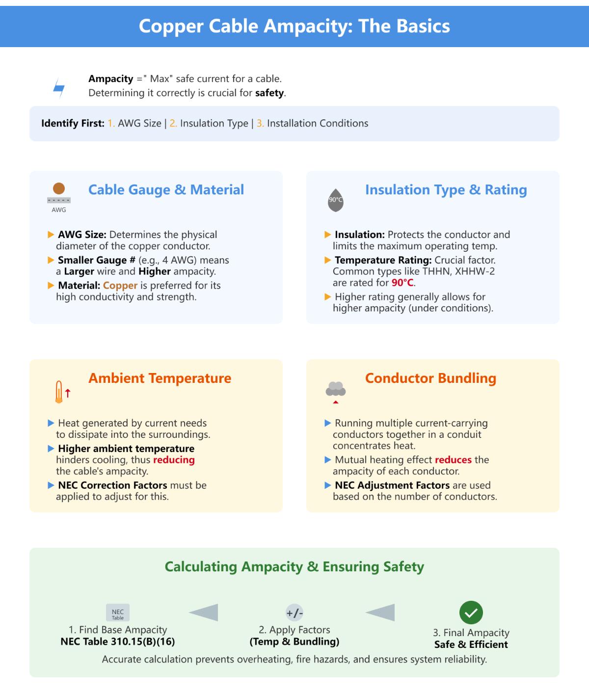
To determine the ampacity for specific copper cable sizes, start by identifying the cable’s American Wire Gauge (AWG) size, insulation type, and the installation environment. Ampacity, or the current-carrying capacity, is influenced by these factors.
Cable Gauge and Material: The AWG size directly affects ampacity; larger diameter cables (smaller gauge numbers) have higher ampacity. Copper is preferred for its high conductivity and durability.
Insulation Type and Temperature Rating: The insulation type impacts the cable’s ampacity. Common types like THHN or XHHW-2 are rated for 90°C, which allows higher ampacity compared to lower temperature-rated insulations.
Ambient Temperature: Higher ambient temperatures reduce the cable’s ampacity. Use NEC correction factors to adjust ampacity according to ambient conditions.
Number of Current-Carrying Conductors: When multiple conductors are in a conduit, their ampacity decreases due to heat buildup. NEC provides adjustment factors for this scenario.
To calculate ampacity, consult NEC Table 310.15(B)(16) for standard conditions, applying necessary adjustment factors for insulation type, ambient temperature, and conductor bundling. Accurate determination ensures safe and efficient electrical installations.
The current carrying capacity (CCC) of copper cables is influenced by several key factors:
Conductor Size and Material: The cross-sectional area of the conductor is a primary determinant of CCC. Larger conductors have lower electrical resistance, allowing more current to flow without excessive heat generation. Copper, due to its superior conductivity compared to materials like aluminum, can carry more current for the same size.
Ambient Temperature: The surrounding temperature affects the cable’s ability to dissipate heat. Higher ambient temperatures decrease CCC because they reduce the efficiency of heat dissipation, necessitating derating to prevent overheating.
Installation Conditions: CCC is higher for cables installed in free air compared to those in enclosed ducts or conduits, where thermal resistance is greater. Additionally, factors like thermal insulation and direct sunlight exposure can significantly reduce CCC due to increased heat retention.
Cable Construction and Bonding: The bonding method impacts heat dissipation. Single-point bonded cables generally have a higher CCC than solidly bonded ones because they allow better heat distribution.
Insulation Material and Temperature Rating: The type and thermal rating of the insulation determine the maximum permissible conductor temperature. Insulations with higher temperature ratings allow higher CCC by permitting greater operating temperatures without damage.
Load Characteristics: Continuous vs. intermittent loading affects CCC. Harmonic currents, particularly third harmonics, increase heating losses and necessitate derating to avoid overheating.
These factors collectively influence the safe current levels that copper cables can carry, ensuring efficient and reliable electrical installations.
Conductor size directly affects power capacity due to its relationship with current carrying capacity, or ampacity. Larger conductors have a greater cross-sectional area, which reduces electrical resistance and allows more current to flow without excessive heating. This is essential for maintaining efficiency and safety in electrical systems.
The American Wire Gauge (AWG) system is commonly used to size conductors, where smaller gauge numbers indicate larger diameters and higher ampacity. For instance, a decrease of three AWG sizes typically doubles the cross-sectional area and significantly increases the current carrying capacity.
Proper conductor sizing is crucial to prevent overheating and ensure the longevity and reliability of electrical installations. Using tools like ampacity charts helps in selecting the right conductor size based on application and environmental conditions, ensuring compliance with electrical codes and optimal performance.
The best conductor material for high current applications is copper. Copper is widely favored due to its excellent electrical conductivity, which is rated at 100% IACS (International Annealed Copper Standard). This high conductivity allows copper to carry higher current densities than other materials, such as aluminum, for the same cross-sectional area, minimizing resistive losses and improving efficiency in high-current systems. Copper’s durability, resistance to thermal expansion, and mechanical strength make it suitable for various applications, including wiring systems, industrial machinery, and electrical appliances. Additionally, copper’s moderate cost and availability make it a practical choice for both residential and industrial installations. While aluminum and silver offer unique advantages in specific scenarios, copper remains the optimal choice for most high-current applications due to its balanced properties and reliability.
Preventing cable overheating in installations involves several key strategies. First, ensure proper cable sizing according to the current carrying capacity to avoid overloading. This can be determined using NEC Table 310.15(B)(16) and ampacity charts. Select cables with appropriate insulation types that can withstand the operating environment’s temperature. Ambient temperature and installation conditions, such as ventilation and spacing, significantly impact heat dissipation. Avoid bundling cables in tight spaces and ensure adequate airflow. Use protective measures like circuit breakers or fuses to guard against electrical overloads. Regular monitoring and maintenance of electrical systems can help identify and mitigate potential overheating issues. By following these practices, the safety and reliability of electrical installations can be maintained.
Yes, several tools are available for calculating the ampacity of copper cables, which are essential for ensuring safe and efficient electrical installations. Online calculators like those provided by Cerrowire and Inch Calculator use National Electrical Code (NEC) standards to determine ampacity based on inputs such as conductor size, insulation type, and environmental conditions. Wire Size Calculator offers detailed charts and calculators aligned with NEC guidelines, aiding in proper wire and conduit sizing. For more complex installations, specialized software like SKM Cable Ampacity module and advanced modeling software such as CYMCAP and ELEK Cable HV Software provide comprehensive ampacity calculations, factoring in elements like neighboring cables and external heat sources. These tools help electrical engineers and designers adhere to safety standards, optimize system performance, and prevent overheating.