Rolling and Bending Angles, Channels, and Pipes
Have you seen those huge metal pipes and tanks in factories? They start as flat sheets! Roll bending is the…
What makes machining precise and efficient? The answer lies in understanding the cutting angles and elements involved. This article explores the essential aspects of cutting motion, tool geometry, and cutting parameters that ensure optimal performance in machining operations. By delving into the mechanics of main, feed, and composite motions, alongside critical tool angles and cutting elements, you’ll gain insights into achieving superior surface quality and dimensional accuracy in your workpieces. Discover how mastering these fundamentals can enhance your machining process and boost overall productivity.
In order to remove excess metal from the workpiece on the machine tool and obtain a workpiece that meets the requirements of dimensional accuracy, geometric accuracy, and surface quality, there must be relative motion between the tool and the workpiece, i.e., cutting motion.
According to the role of cutting motion in the cutting process, cutting motion can be divided into main motion and feed motion, as shown in Figure 1.
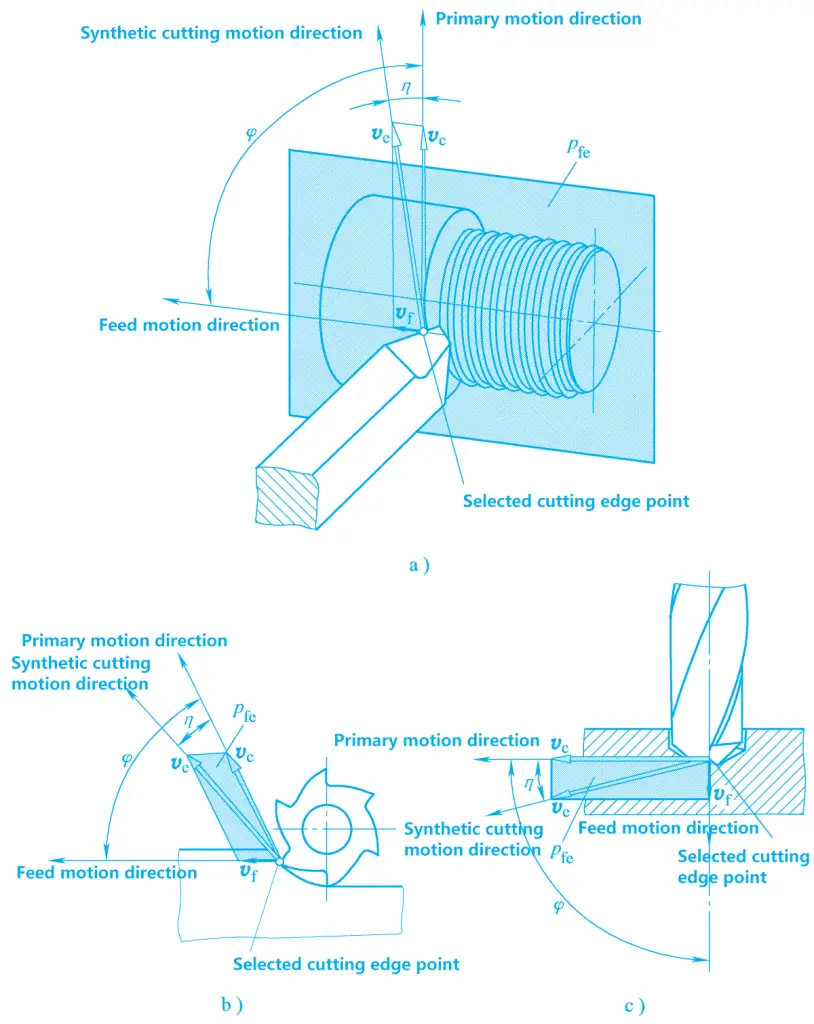
a) Turning
b) Milling
c) Drilling
The main motion is the necessary motion to remove the excess metal layer from the workpiece and form a new surface on the workpiece. It is the primary motion provided by the machine tool. The main motion is characterized by the highest speed and the most power consumption.
There is only one main motion in cutting processing, which can be performed by the workpiece or the tool. For example, the rotational motion of the workpiece during turning, and the rotational motion of the milling cutter and drill bit during milling and drilling, respectively, are all main motions.
The feed motion is a motion that intermittently or continuously feeds the metal layer to be cut into the cutting process. When combined with the main motion, it continuously removes the metal layer to obtain the desired workpiece surface. The feed motion is characterized by low speed and low power consumption.
In cutting processing, the feed motion can be one, two, or multiple motions. It can be a continuous motion, such as the longitudinal motion of the lathe tool parallel to the workpiece axis during external turning, or an intermittent motion, such as the transverse motion of the workpiece or tool during planing.
As shown in Figure 1, the composite cutting motion is a motion synthesized from the main motion and the feed motion. The instantaneous composite motion direction of a selected point on the cutting edge of the tool relative to the workpiece is called the composite cutting motion direction, and its speed is called the composite cutting speed.
During the cutting process, the metal layer on the workpiece is continuously cut off by the tool and becomes chips, while a new surface is formed on the workpiece. During the formation of the new surface, there are three continuously changing surfaces on the workpiece, as shown in Figure 2.
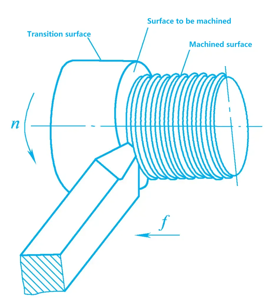
The surface on the workpiece to be removed is called the surface to be machined.
The surface formed on the workpiece after cutting by the tool is called the machined surface.
The surface being cut by the cutting edge is called the transition surface, which is the connecting surface between the surface to be machined and the machined surface.
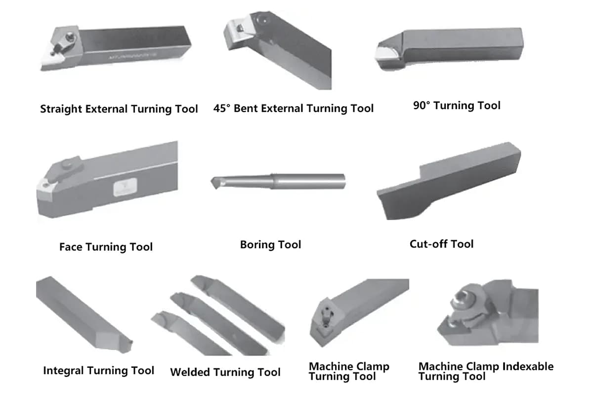
There are many types and shapes of metal cutting tools, but the composition of the cutting part of the tool has common points. The cutting part of the external turning tool can be regarded as the most basic form of the cutting part of various tools. The general terms describing the cutting part of the turning tool can also be used for other metal cutting tools.
The turning tool consists of a tool shank and a tool head. The tool shank is the clamping part of the tool, and the tool head is the cutting part of the tool. As shown in Figure 3, the tool head is composed of the following parts:
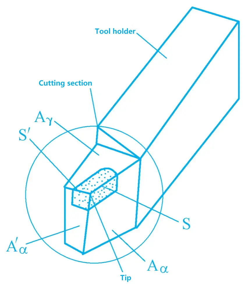
The tool face through which the chips flow out is called the rake face.
The tool face opposite to the transition surface is called the flank face (also called the main flank face).
The tool face opposite to the machined surface is called the secondary flank face.
The intersection line between the rake face and the main flank face is called the main cutting edge. It undertakes the main cutting task during the cutting process.
The intersection line between the rake face and the secondary flank face is called the secondary cutting edge. It cooperates with the main cutting edge to complete the cutting work and finally forms the machined surface of the workpiece.
The tool tip is the connecting part of the main and secondary cutting edges, or the intersection point of the main and secondary cutting edges. Most tools have a small straight edge or arc edge ground at the tool tip, while some tools have the main and secondary cutting edges directly intersect to form a sharp tool tip, as shown in Figure 4.
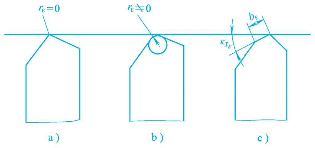
a) Sharp tool tip
b) Rounded tool tip
c) Chamfered tool tip
Different types of tools may have different numbers of tool faces and cutting edges, but the most basic unit of the cutting part of the tool consists of two tool faces (Aγ , Aα ) and one main cutting edge. Any complex multi-edge tool can be analyzed by decomposing it into basic units.
In order to analyze the spatial positions of the tool faces and cutting edges of the cutting part of the tool, and to facilitate the design, manufacture, grinding, and measurement of the tool, a spatial coordinate plane reference system must be established, called the stationary angle reference system of the tool.
To facilitate the analysis of the role of the geometric angles of the tool during the cutting process, the establishment of the coordinate planes in the stationary angle reference system of the tool should be based on the cutting motion.
First, the assumed working conditions are given, which include the assumed motion conditions and assumed installation conditions, and then a reference system is established. The tool geometry angles determined in this reference system are called the static angles of the tool, i.e., the annotated angles.
1) Assumed motion conditions
The instantaneous main motion direction of the selected point on the cutting edge (when located in the plane of the workpiece rotation center) relative to the workpiece is taken as the assumed main motion direction; the instantaneous feed motion direction of the selected point on the cutting edge relative to the workpiece is taken as the assumed feed motion direction, generally ignoring the impact of the feed motion magnitude, i.e., assuming the feed rate f=0.
2) Assumed installation conditions
It is assumed that the lathe tool is installed absolutely correctly, i.e., when installing the lathe tool, the tool tip should be at the same height as the workpiece rotation center, and the symmetrical plane of the lathe tool shank should be perpendicular to the workpiece rotation axis.
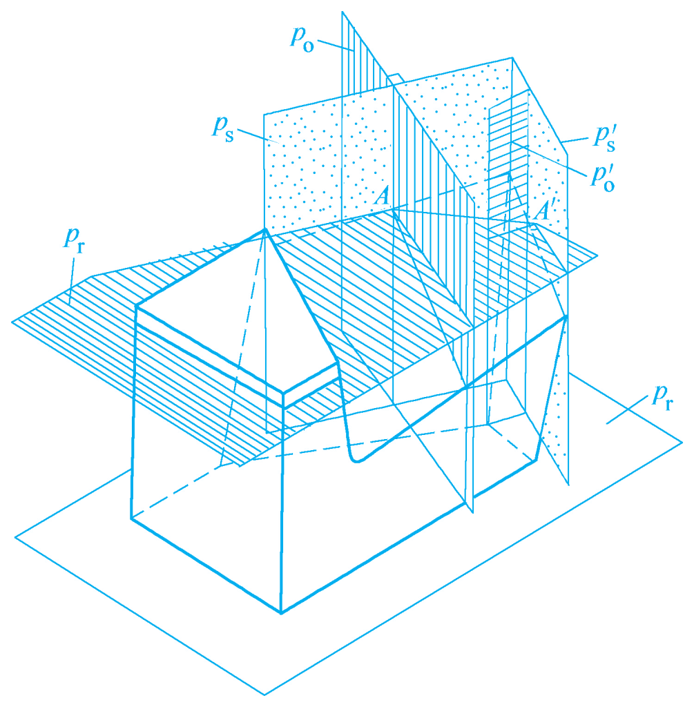
1) Base plane pr
The plane passing through the selected point on the cutting edge and perpendicular to the assumed main motion direction is called the base plane. For a lathe tool, the base plane is parallel to the bottom surface of the lathe tool shank.
2) Cutting plane ps
The plane passing through the selected point on the cutting edge, tangent to the main cutting edge, and perpendicular to the base plane is called the cutting plane.
3) Orthogonal plane po
The plane passing through the selected point on the cutting edge and perpendicular to both the base plane and the cutting plane.
The commonly used orthogonal plane static reference system and angle annotation are introduced below.
The orthogonal plane reference system consists of the base plane pr, the cutting plane ps, and the orthogonal plane p. These three mutually perpendicular coordinate planes form the system, as shown in Figure 5.
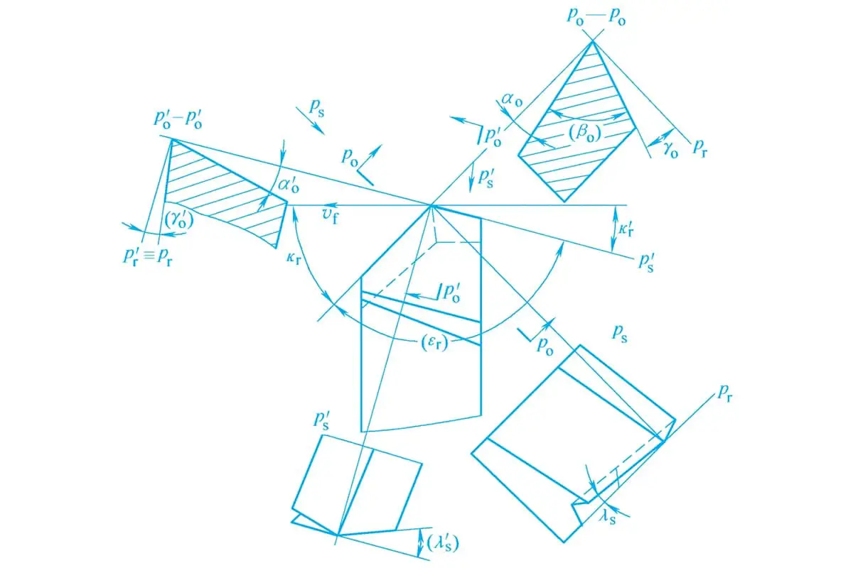
The following angles can be annotated in this reference system, as shown in Figure 6.
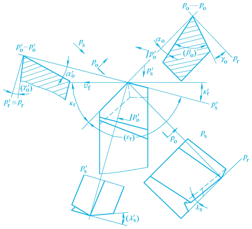
1) Main declination angle kr
The angle between the main cutting edge and the assumed feed motion direction measured in the base plane is called the main declination angle.
2) Cutting edge inclination angle λs
The angle between the main cutting edge and the base plane passing through the tool tip measured in the cutting plane is called the cutting edge inclination angle.
3) Rake angle γo
The angle between the rake face and the base plane measured in the orthogonal plane is called the rake angle.
4) Clearance angle αo
The angle between the clearance face and the cutting plane measured in the orthogonal plane is called the clearance angle.
The orientation of the rake face, clearance face, and main cutting edge can be determined using the above four angles. The rake angle γo and the cutting edge inclination angle λs determine the orientation of the rake face, the main declination angle kr and the clearance angle αo determine the orientation of the clearance face, and the main declination angle kr and the cutting edge inclination angle λs determine the orientation of the main cutting edge.
Similarly, by selecting a point on the auxiliary cutting edge, the auxiliary base plane p’r , auxiliary cutting plane p’s , and auxiliary orthogonal plane p’o can also be established. The corresponding positions of the auxiliary rake face and auxiliary flank face are determined by the auxiliary inclination angle k’r , auxiliary edge inclination angle λ’s , auxiliary rake angle γ’o , and auxiliary clearance angle α’o .
Since the auxiliary cutting edge and the main cutting edge are both on the same rake face, once the angles γo and λs are determined, the position of the rake face is fixed. Consequently, the angles γ’o and λ’s are also determined. Therefore, to determine the position of the auxiliary flank face, it is usually only necessary to determine the auxiliary inclination angle k’r and the auxiliary clearance angle α’o through the auxiliary cutting edge.
5) Auxiliary inclination angle k’r
The angle between the auxiliary cutting edge and the assumed feed direction measured in the base plane is called the auxiliary inclination angle.
6) Auxiliary clearance angle α’o
The angle between the auxiliary flank face and the auxiliary cutting plane measured in the auxiliary orthogonal plane is called the auxiliary clearance angle.
Therefore, the external turning tool shown in Figure 6 has three faces and two cutting edges, with only six independent angles that need to be marked: γo , αo , kr , k’r , λs , α’o . Among them, kr and k’r are marked in the base plane, γo and αo are marked in the orthogonal plane, λ s is marked in the cutting plane, and α’o is marked in the auxiliary orthogonal plane.
The following two derived angles are often used when analyzing tools (the two angles in parentheses in Figure 6):
7) Wedge angle βo
The angle between the rake face and the flank face measured in the orthogonal plane is called the wedge angle.
βo = 90° – (γo + αo )
8) Tool tip angle εr
The angle between the main and auxiliary cutting edges measured in the base plane is called the tool tip angle.
εr = 180° – (kr + k’r )
As shown in Figure 7a, when the rake face is parallel to the base plane, the rake angle is zero; when the angle between the rake face and the cutting plane is less than 90°, the rake angle is positive; when it is greater than 90°, the rake angle is negative. When the angle between the flank face and the base plane is less than 90°, the clearance angle is positive; when it is greater than 90°, the clearance angle is negative.
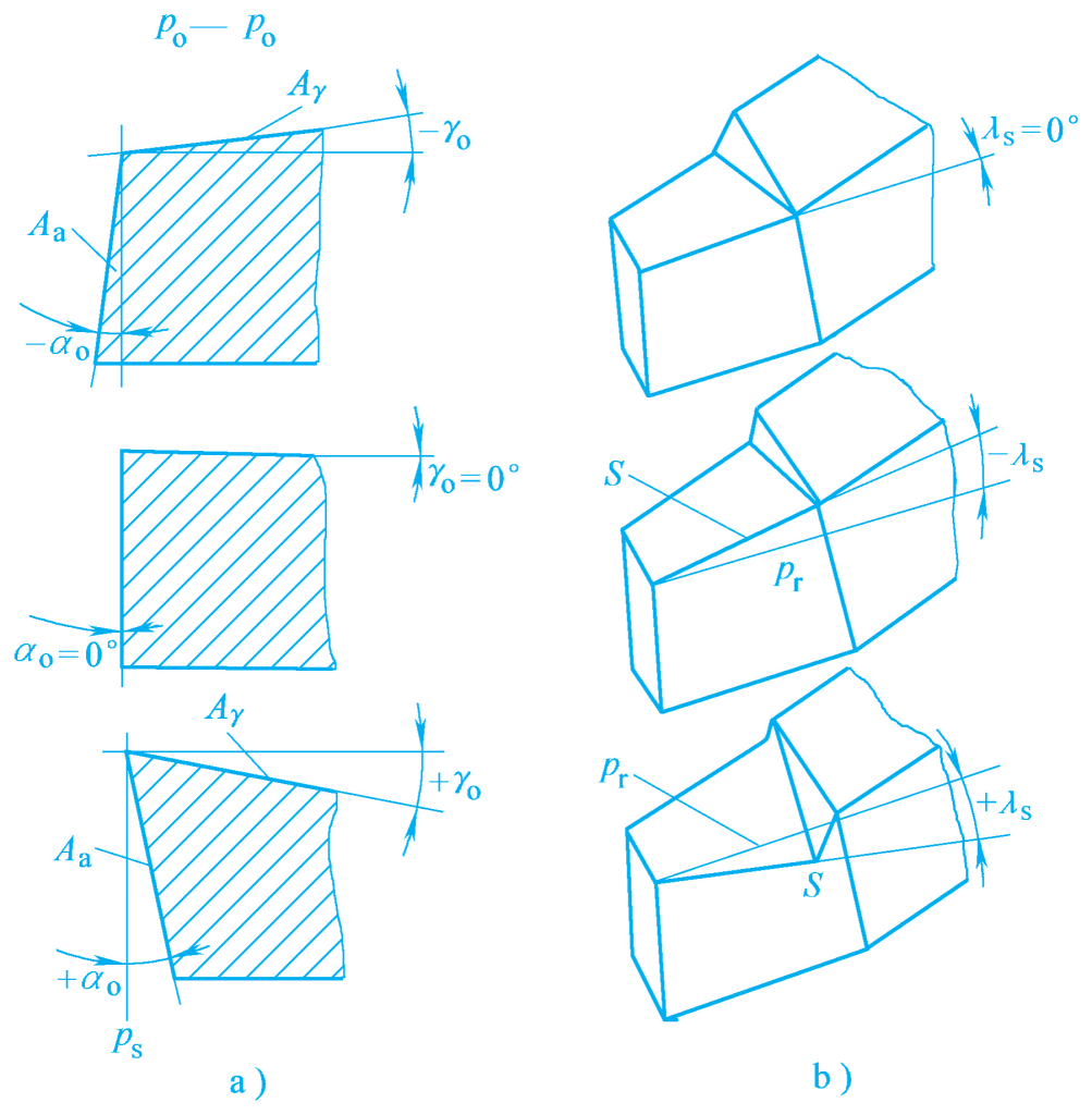
a) Rake and clearance angles
b) Edge inclination angle
As shown in Figure 7b, when the tool tip is at the highest point of the cutting edge, the edge inclination angle is positive; when the tool tip is at the lowest point of the cutting edge, the edge inclination angle is negative; when the cutting edge coincides with the base plane, the edge inclination angle is zero.
The main and auxiliary inclination angles range between 0° and 90°.
Cutting elements are divided into two main categories: cutting amount elements and cutting layer elements.
During the cutting process, appropriate cutting amount elements should be selected based on different workpiece materials, tool materials, and other technical and economic factors. Cutting speed, feed rate, and depth of cut are called the three elements of cutting amount, also known as process cutting elements (see Figure 8). Cutting amount elements are used to correctly adjust the machine tool to ensure processing quality, high productivity, and low processing costs.
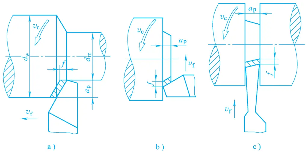
a) External turning
b) Facing
c) Grooving
Cutting speed is the instantaneous speed of a point on the cutting edge of the tool relative to the surface to be machined in the main motion direction. When turning an external cylinder, the calculation formula is as follows:
vc = πdw n / 1000
Where
The cutting speed at various points on the cutting edge is different. When calculating, the maximum cutting speed should be used. For example, when turning the outer circle, the diameter of the surface to be machined is used for calculation because the speed is highest here, and the tool wears out the fastest.
The feed rate is the displacement of the tool relative to the workpiece in the feed motion direction. It can be expressed as the displacement per revolution or per stroke of the tool or workpiece. When the main motion is rotational, the unit of f is mm/r.
For multi-tooth tools such as milling cutters and reamers, the feed per tooth f z is also specified, which is the relative displacement of the multi-tooth tool per tooth passing relative to the workpiece in the feed motion direction, in mm/z. The feed rate is also often expressed as the feed speed v f , which is the instantaneous speed of the selected point on the cutting edge relative to the workpiece in the feed motion direction, in mm/min.
vf = fn
That is
vf = fz zn
In the formula, z is the number of teeth.
The depth of cut generally refers to the vertical distance between the surface to be machined and the machined surface on the workpiece. When turning the outer circle:
ap=(dw-dm)/2
Where
The metal layer cut off from the surface to be machined by the tool cutting edge in one feed is called the cutting layer. When turning the outer circle, the workpiece rotates once, and the tool moves from position I to position II, advancing by one feed rate. The shaded part in Figure 9 is the cutting layer.
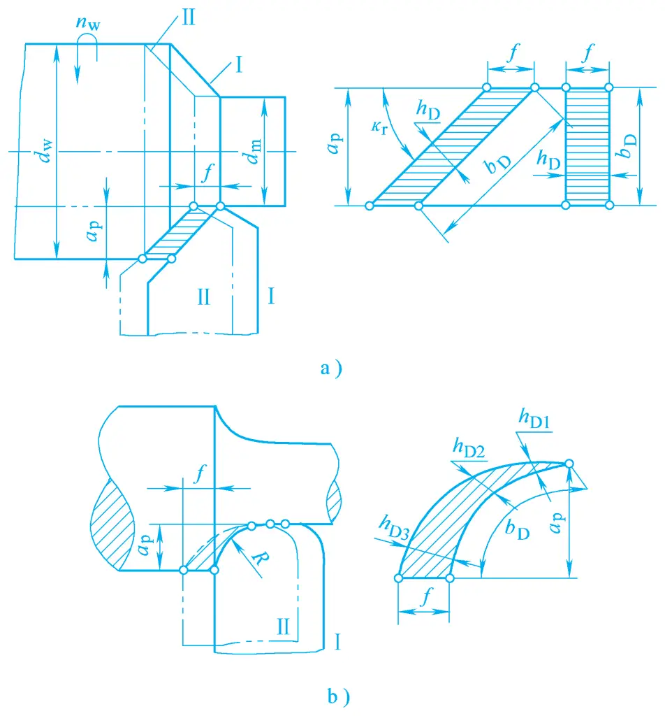
a) For straight edges
b) For curved edges
The size of its cross-sectional dimensions is the cutting layer parameter, which determines the load on the tool and the size of the cutting layer. It also affects the cutting force, tool wear, workpiece surface quality, and productivity.
The cutting layer size can be expressed by the following three parameters:
The nominal thickness of the cutting layer refers to the distance between the transition surfaces of the two instantaneous positions of the cutting edge.
The nominal width of the cutting layer refers to the size of the cutting layer measured along the transition surface.
The nominal cross-sectional area of the cutting layer refers to the area of the cross-section of the cutting layer.