Metal cutting is the process of removing excess metal from parts using a cutting tool in relative motion with the workpiece, resulting in chip formation and a machined surface.
The metal cutting process involves the shear deformation of the metal layer being cut under the action of the cutting tool. This process is accompanied by physical phenomena such as metal deformation, cutting forces, cutting heat, and tool wear. Problems that occur in the production process, such as burrs, built-up edges, vibration, chip curling and breaking, are all related to the cutting process.
I. Cutting Process
1. Chip Formation Process
During cutting, under the cutting action of the cutting edge and the pushing action of the rake face, the metal layer being cut undergoes shearing, sliding, and deformation, finally separating from the workpiece to become chips. This process is called the cutting process.
The chip formation process is shown in Figure 1.
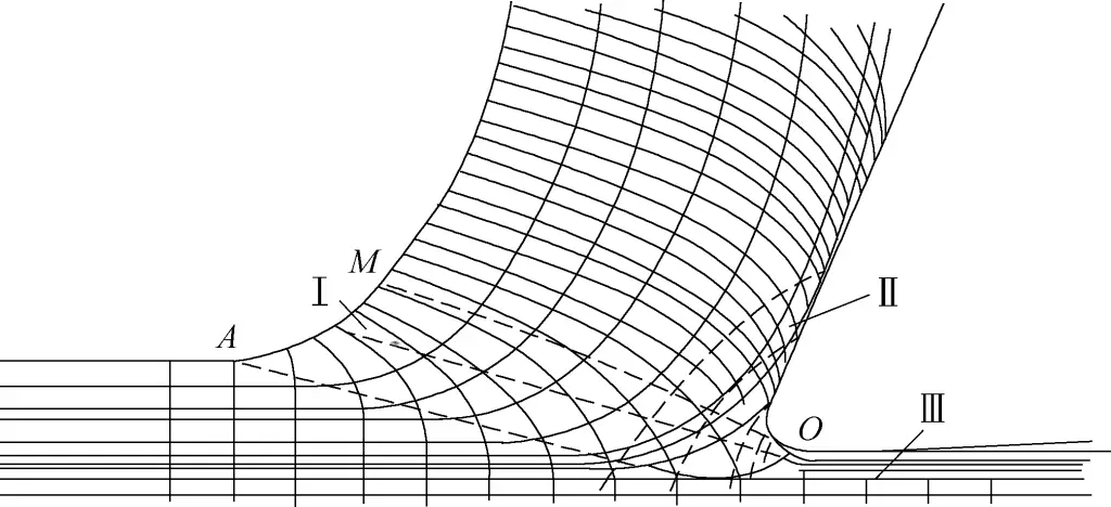
Zone I Deformation: The shear deformation zone in the cutting layer near the cutting edge.
The metal layer being cut first undergoes elastic deformation under the compressive force in front of the cutting tool. When the maximum shear stress reaches the material’s yield limit, shear sliding occurs. As the rake face approaches gradually, plastic deformation increases, accompanied by strain hardening, until sliding stops, and the cut metal layer separates from the workpiece body to become chips flowing along the rake face.
Zone II Deformation: The deformation zone in the chip layer in contact with the rake face.
The chips formed by shear sliding in the first deformation zone undergo intense friction with the rake face as they flow out, causing a second shear deformation that slows down the flow of a thin layer of metal at the bottom of the chip. This layer of slow-flowing metal is called the stagnant layer. The degree of deformation in the stagnant layer is several times or even tens of times greater than that in the upper layer of the chip.
Zone III Deformation: The deformation zone in the machined surface layer near the cutting edge.
The deformation in the third deformation zone refers to the area where the workpiece surface and machined surface metal layer undergo plastic deformation due to compression and friction from the blunt part of the cutting edge and the flank face. This causes fibrosis and work hardening of the surface metal layer and produces certain residual stresses. The metal deformation in this zone will affect the surface quality and performance of the workpiece.
2. Types of Chips
During metal cutting, due to differences in workpiece materials, tool geometry, and cutting parameters, the formed chips have various shapes. There are generally four basic types (see Figure 2).

a) Continuous chips
b) Segmented chips
c) Elemental chips
d) Discontinuous chips
(1) Continuous chips
(See Figure 2a) Chips form in a continuous ribbon. The inner surface of continuous chips is smooth, while the outer surface is fuzzy. Under a microscope, many shear plane striations can be seen on the side. These chips are easily formed when cutting ductile metals with small cutting thickness, high cutting speed, and large tool rake angle.
The advantages of forming this type of chip are stable cutting process, small fluctuation in cutting force, and high surface quality of the workpiece. The disadvantage is that excessively long continuous chips can wrap around the workpiece and tool, affecting operation and safety. Therefore, chip-breaking measures must be taken.
(2) Segmented chips
(See Figure 2b) The outer surface of these chips is serrated, and the inner surface has cracks. This is because the local shear stress inside reaches the material’s strength limit during cutting.
When cutting ductile metals, these chips are easily obtained with larger cutting thickness, lower cutting speed, and smaller rake angle. During the formation of these chips, the cutting force fluctuates greatly, the cutting process is less stable, and it tends to cause a rougher machined surface on the workpiece.
(3) Elemental chips
(See Figure 2c) If the chips break into larger irregular block structures during cutting, these chips are called elemental chips. The reason for forming these chips is that the shear stress inside the chip exceeds the material’s strength limit, causing the chip to fracture along a certain cross-section, preventing the formation of continuous chips. Generally,
when cutting ductile metals, these chips are easily obtained with large cutting thickness, low cutting speed, and small tool rake angle. When forming these chips, the cutting force fluctuates greatly, the cutting process is very unstable, and the machined surface roughness of the workpiece is high. Therefore, the formation of these chips should be avoided during machining, especially in finishing operations.
(4) Discontinuous chips
(See Figure 2d) When cutting brittle metals (such as cast iron, brass), the metal layer being cut is squeezed and brittle-fractured with very little plastic deformation under the pushing action of the tool. This forms irregular fragmented chips of various sizes, called discontinuous chips.
When forming these chips, the cutting force varies greatly, and the machined surface roughness of the workpiece is very high. The smaller the tool rake angle and the larger the cutting thickness, the more likely these chips are to be produced.
3. Built-up Edge
(1) Formation of Built-up Edge
Under certain conditions, when cutting ductile metals, a small piece of metal with higher hardness adheres near the tool tip, as shown in Figure 3. This piece of metal is called a built-up edge. It has a significant impact on the cutting process and the quality of the machined surface.

The formation of a built-up edge requires certain conditions and reasons. First, it occurs when cutting ductile metals, and second, at medium cutting speeds (5-60m/min). When cutting general steel or other ductile materials, the metal layer being cut is forced to separate from the parent material under the cutting action of the tool’s cutting edge. The bottom layer flows along the tool’s face, causing friction between the cutting layer and the rake face.
At the same time, during the cutting process, the pushing action of the tool’s face on the chip produces enormous pressure. The huge pressure and friction cause the flow speed of the metal at the bottom layer of the chip to be much slower than the upper layer, resulting in significant deformation along the rake face, known as stagnation flow.
When the pressure and temperature between the chip and the rake face reach a certain level, cold welding occurs. The bottom layer of the cut metal that has undergone cold welding stays on the rake face, forming a layer of built-up edge. This layer of built-up edge causes the layer of metal in contact with it to undergo significant plastic deformation and accumulate on top of it.
Through continuous accumulation, the built-up edge gradually grows larger. When it reaches a certain height, it forms a complete built-up edge and replaces the cutting edge in the cutting process. The presence of the built-up edge changes the rake angle of the tool.
When the cutting speed is very low (<5m/min), the pressure and temperature between the tool face and the cutting layer are low, not meeting the conditions for forming a built-up edge. When the cutting speed is very high, the temperature of the bottom layer of metal is very high. The fluidity of the bottom layer metal increases, and the friction coefficient decreases significantly, also preventing the formation of a built-up edge.
(2) Impact of Built-up Edge on Cutting
1) Protects the tool.
The hardness of the built-up edge is about 2-4 times that of the workpiece material. Welded to the front of the tool, it can replace the cutting edge in cutting, protecting the cutting edge and rake face, and reducing tool wear. The built-up edge has a positive effect on rough machining.
2) Increases the effective rake angle.
A turning tool with a built-up edge can increase the effective rake angle to 30°-35°, reducing chip deformation and lowering cutting forces, as shown in Figure 4.
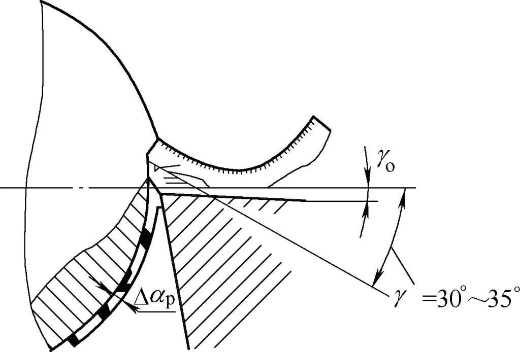
3) Affects workpiece dimensional accuracy and surface quality.
The formation of built-up edge is intermittent, varying in size and highly unstable. During the cutting process, some built-up edges are carried away by chips, while others are embedded in the machined surface of the workpiece, creating hard spots and burrs, increasing the surface roughness value, as shown in Figure 5.

When the built-up edge grows larger than the cutting edge, the actual position of the tool tip changes, causing a change in the depth of cut, affecting the dimensional accuracy of the workpiece. Therefore, in finish machining, the formation of built-up edge can be avoided by changing the three cutting parameters.
(3) Main Factors Affecting Built-up Edge
The main factors affecting built-up edge are workpiece material, cutting speed, feed rate, and cutting fluid. Among these, cutting speed has the greatest impact on the formation of built-up edge. In addition, tool rake angle and cutting thickness also affect built-up edge formation.
A larger rake angle reduces chip deformation, which helps suppress the formation of built-up edge. An increase in cutting thickness also increases the contact length between the chip and the rake face, increasing the possibility of built-up edge formation.
4. Work Hardening
The phenomenon where the surface strength and hardness of ductile metals increase while plasticity decreases after machining is called work hardening, also known as strain hardening. The cause of strain hardening is the plastic deformation of metal materials during the machining process.
The greater the plastic deformation, the more severe the surface strain hardening. The hardness of the hardened layer can reach 1.2-2 times the workpiece hardness, with a hardened layer depth of 0.07-0.5mm. This creates difficulties for subsequent machining, increases tool wear, and affects the surface quality of the workpiece. The occurrence of strain hardening is accompanied by residual stress and micro-cracks, which will reduce the material properties of the workpiece surface.
Although strain hardening has some adverse effects, it also has beneficial aspects. For example, under conditions that suppress residual stress, especially micro-cracks, using roller burnishing to produce work hardening can improve the hardness, strength, and wear resistance of the machined surface.
II. Cutting Force
The force exerted by the cutting tool on the workpiece during cutting is called the cutting force F r , which acts on the workpiece. The resistance of the workpiece material against the tool’s cutting action is called the cutting resistance F’ r , which acts on the tool.
The cutting force F r and cutting resistance F’ r are a pair of equal and opposite forces acting on two different objects, as shown in Figure 6.

Cutting resistance has a significant impact on tool life, machine power consumption, and workpiece processing quality during the cutting process.
1. Sources of cutting resistance
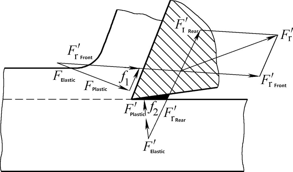
During cutting, the tool is not only subjected to deformation resistance (F₀, F₁, F₂, F₃) produced by the plastic and elastic deformation of the cut metal, chips, and workpiece surface layer, but also to frictional resistance (f₄, f₅) between the rake face and chips, and between the flank face and workpiece surface. The cutting resistance is the resultant force (vector sum) of these forces, as shown in Figure 7.
2. Decomposition of cutting resistance
The cutting resistance F’₀ is a spatial vector, and its magnitude and direction are not easy to measure. To facilitate analysis of the cutting resistance’s effect and measurement, and to calculate the magnitude of the cutting force, the cutting resistance F’₁ is usually decomposed into three mutually perpendicular components: main cutting resistance F’₂, radial resistance F’y, and axial resistance F’x (see Figure 8).
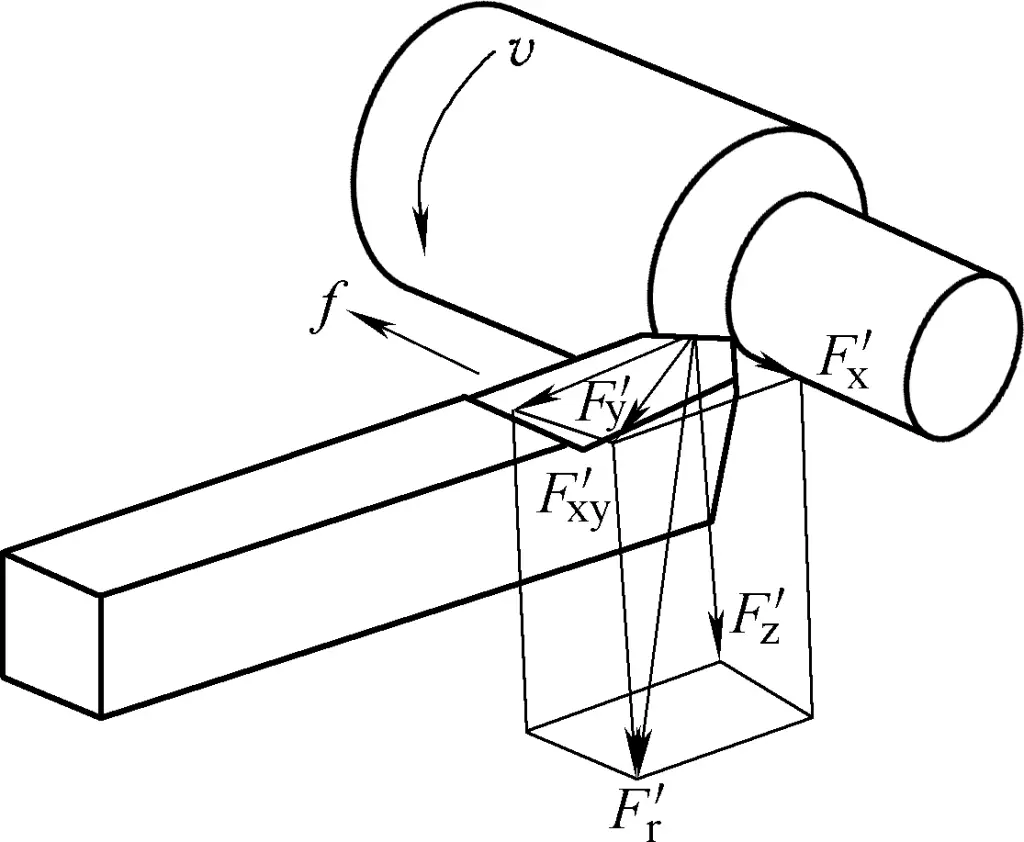
When the values of the three component forces are known, the value of the resultant force F’₀ can be calculated using the following formula:

(1) Main cutting resistance F’₀
It is perpendicular to the base plane and consistent with the direction of cutting speed v₀. It is the largest of the component forces, consuming the most power, accounting for about 95% to 99% of the total machine power. F’₁ will cause the tool shank to bend. Therefore, when installing the tool, the tool shank should be extended as short as possible.
(2) Radial resistance F’y
It is in the base plane and parallel to the radial feed direction. It does not consume machine power. However, its reactive radial cutting force acts on the workpiece radially, tending to bend the workpiece. When the workpiece is slender and the technological system lacks rigidity, it is easy to produce bending deformation and vibration, affecting machining accuracy and surface roughness.
(3) Axial resistance F’x
It is in the base plane and parallel to the longitudinal feed direction. It only consumes 1% to 5% of the total machine power. Since it is parallel to the workpiece axis, it tends to deflect the lathe tool in the opposite direction of the feed. Therefore, when installing the lathe tool, it should be securely locked to avoid workpiece scrapping due to tool movement.
3. Factors affecting cutting resistance
(1) Workpiece material
The hardness, strength, plastic deformation, and friction between chips and tools of the workpiece material all affect cutting resistance. The higher the hardness or strength of the workpiece material, the greater the cutting resistance.
The higher the plasticity or toughness of the workpiece material, the greater the deformation resistance and friction force, and the greater the cutting resistance. The strength and deformation of steel are greater than those of cast iron, so the cutting resistance when cutting steel is greater than when cutting cast iron (about 0.5 to 1 times higher).
(2) Cutting parameters
Among cutting parameters, the main factors are depth of cut and feed rate, which affect cutting resistance by influencing the cutting area. The depth of cut has the greatest impact on cutting resistance, followed by the feed rate.
Increasing the depth of cut and feed rate will increase the cutting thickness and cutting width respectively, thus increasing the cutting area. As a result, the deformation resistance and frictional resistance increase, leading to an increase in cutting resistance.
When the depth of cut is doubled, the main cutting resistance also doubles; but when the feed rate is doubled, the main cutting resistance only increases by 0.75 to 0.9 times. Therefore, using a larger feed rate is more power-efficient than using a larger depth of cut.
Cutting speed affects cutting resistance by influencing the degree of chip deformation, but it has no effect on the cutting area. Therefore, the impact of cutting speed on cutting resistance is not as significant as that of depth of cut and feed rate. When cutting brittle metals, the deformation and friction are relatively small, and the cutting force does not change much when the cutting speed changes.
(3) Lathe tool angles
1) Rake angle.
The larger the rake angle, the smaller the chip deformation, and the cutting resistance is significantly reduced.
2) Approach angle.
When cutting plastic metals, if the approach angle is less than 60° to 75°, increasing the approach angle will reduce the main cutting resistance; when the approach angle is greater than 60° to 75°, increasing the approach angle will increase the main cutting resistance due to the influence of the tool nose radius. When cutting brittle metals, the main cutting resistance basically does not change with the angle change when the approach angle is greater than 45°.
3) Inclination angle.
When the inclination angle varies from 10° to 45°, the main cutting resistance remains basically unchanged. However, when the inclination angle decreases, the radial cutting resistance increases, and the feed force decreases.
4) Negative land.
When the tool is ground with a negative land, the cutting edge becomes blunt, chip deformation increases, and cutting resistance also increases.
5) Tool nose radius.
As the tool nose radius or transition edge increases, the length of the cutting edge involved in cutting increases, chip deformation and friction force increase, and cutting resistance also increases.
III. Cutting Heat and Cutting Temperature
Cutting heat is the heat generated during the cutting process due to metal deformation and friction. Cutting heat and the resulting cutting temperature directly affect tool wear and service life, and influence workpiece machining accuracy and surface quality, especially in high-speed cutting.
1. Sources and Dissipation of Cutting Heat
There are three sources of cutting heat: first, elastic and plastic deformation of the cutting layer metal; second, friction between the chip and the rake face; third, friction between the workpiece and the flank face. During the cutting process, most of the power consumed by the above deformation and friction is converted into heat energy.
Cutting heat is dissipated through chips, workpiece, tool, and surrounding medium. Experiments have shown that the proportion of cutting heat transferred to various parts is generally highest in chips.
Without using cutting fluid, when cutting steel materials at medium cutting speed, 50% to 86% of the cutting heat is carried away by chips, 10% to 40% is transferred to the workpiece, 3% to 9% is transferred to the lathe tool, and about 1% is transferred to the surrounding air.
2. Cutting Temperature
The generation of cutting heat causes the temperature in the cutting zone to rise, and the distribution of cutting temperature in the cutting zone is uneven. The cutting temperature usually refers to the average temperature in the contact area between the chip and the rake face. The level of cutting temperature depends on the amount of cutting heat and the quality of heat dissipation conditions.
3. Main Factors Affecting Cutting Temperature
(1) Influence of workpiece material
The workpiece material affects cutting temperature through its different strength, hardness, and thermal conductivity properties. When the workpiece material has lower strength and hardness, and higher thermal conductivity, less heat is generated, resulting in a lower cutting temperature. The opposite is true for higher cutting temperatures.
(2) Influence of cutting parameters
Increasing cutting parameters (v₀, f, a₁) raises the cutting temperature, with cutting speed (v₂) having the greatest impact, followed by feed rate (f), and depth of cut (a₃) having the least influence.
(3) Influence of tool angles
1) Rake angle (γ₀)
The size of the rake angle affects cutting deformation and friction, significantly impacting cutting temperature. As the rake angle increases, deformation and friction decrease, less heat is generated, and cutting temperature drops. However, if the rake angle is too large, the wedge angle decreases, reducing the tool tip volume and worsening heat dissipation conditions, causing the cutting temperature to rise slightly.
2) Approach angle (K₀)
Under the same depth of cut, increasing the approach angle shortens the length L₀ of the main cutting edge participating in cutting, and reduces the tool point angle ε₁. This concentrates the cutting heat and worsens heat dissipation conditions, leading to a rise in cutting temperature, as shown in Figure 9.
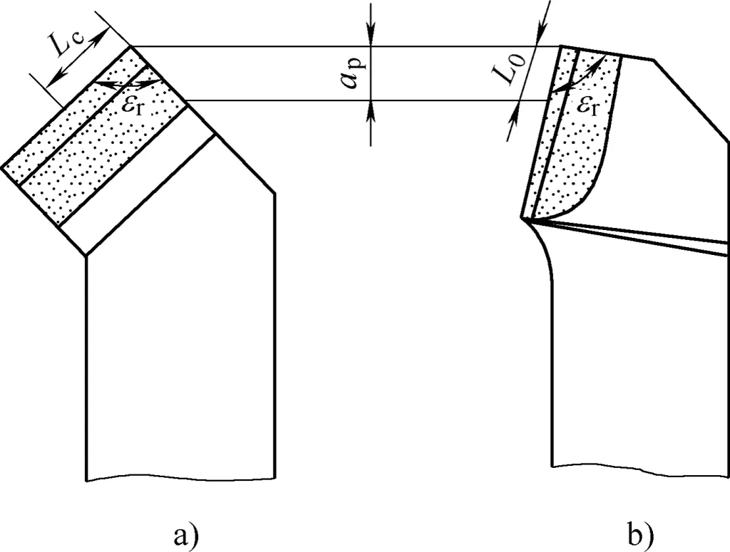
a) Small K₀, large tool point angle
b) Large K₀, small tool point angle
(4) Influence of other factors
Proper selection and sufficient application of cutting fluid can effectively reduce cutting temperature.
4. Effects of Cutting Temperature on Machining
The effects of cutting temperature on cutting and machining have dual nature.
(1) Adverse effects of cutting temperature on cutting and machining
1) Rising cutting temperature accelerates tool wear and reduces tool life.
2) After heating, tools or workpieces may experience thermal expansion and deformation, affecting machining accuracy, especially when machining non-ferrous metals or slender workpieces.
3) When the workpiece surface contacts the tool flank, the temperature can rise to several hundred degrees instantly, but drops rapidly after separating from the flank. Although this process is brief, it can cause harmful residual tensile stress on the workpiece surface. In severe cases, it may cause surface burning and annealing phenomena on the workpiece.
(2) Beneficial effects of cutting temperature on cutting and machining
1) Cutting temperature softens the workpiece material, making it easier to cut, which is beneficial for machining materials with high hardness but low high-temperature strength (such as quenched and hardened steel).
2) For some tool materials that are brittle but have good heat resistance (such as cemented carbides and ceramic materials), appropriate high temperatures can improve the material’s toughness and reduce chipping phenomena.
3) Higher cutting temperatures are unfavorable for the formation of built-up edges, which can reduce tool wear and improve workpiece surface quality.
IV. Tool Wear and Wear Criteria
Tools will gradually wear during the cutting process. When the tool wear reaches a certain level, it can be clearly observed that the cutting resistance increases, cutting temperature rises, chip color changes, cutting vibration occurs, and the machined surface quality deteriorates significantly. The workpiece dimensions may not meet requirements. At this point, the tool must be resharpened or replaced with a new one.
1. Forms of Tool Wear
There are three forms of tool wear: rake face wear, flank face wear, and simultaneous wear of rake and flank faces, as shown in Figure 10.
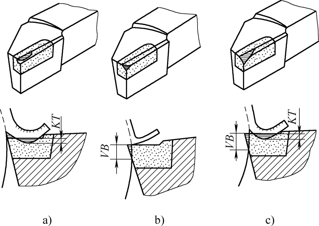
a) Rake face wear
b) Flank face wear
c) Simultaneous wear of rake and flank faces
(1) Rake face wear
Rake face wear refers to the appearance of a crescent-shaped pit on the front of the tool. When cutting plastic metals with higher cutting speeds and larger cutting thicknesses, crescent-shaped pits are more likely to occur. The gradual expansion of crescent-shaped wear will reduce the strength of the cutting edge, making it easy to chip and damage the tool.
(2) Flank face wear
The main area of wear occurs on the flank face. It is caused by intense squeezing and friction between the machined surface and the tool’s flank face, resulting in damage and grooves near the cutting edge on the flank face.
This type of wear generally occurs when cutting brittle metals or when cutting plastic metals with a small depth of cut (a p <0.1mm). The wear value is represented by VB.
(3) Simultaneous wear of rake and flank faces
This is a comprehensive type of wear, referring to the simultaneous occurrence of crescent-shaped pits on the rake face and grooves on the flank face. When cutting plastic metals, this is the most common situation. Pure rake face wear or flank face wear rarely occurs.
2. Tool wear process
The tool wear process can generally be divided into three stages. The tool wear process curve is shown in Figure 11.
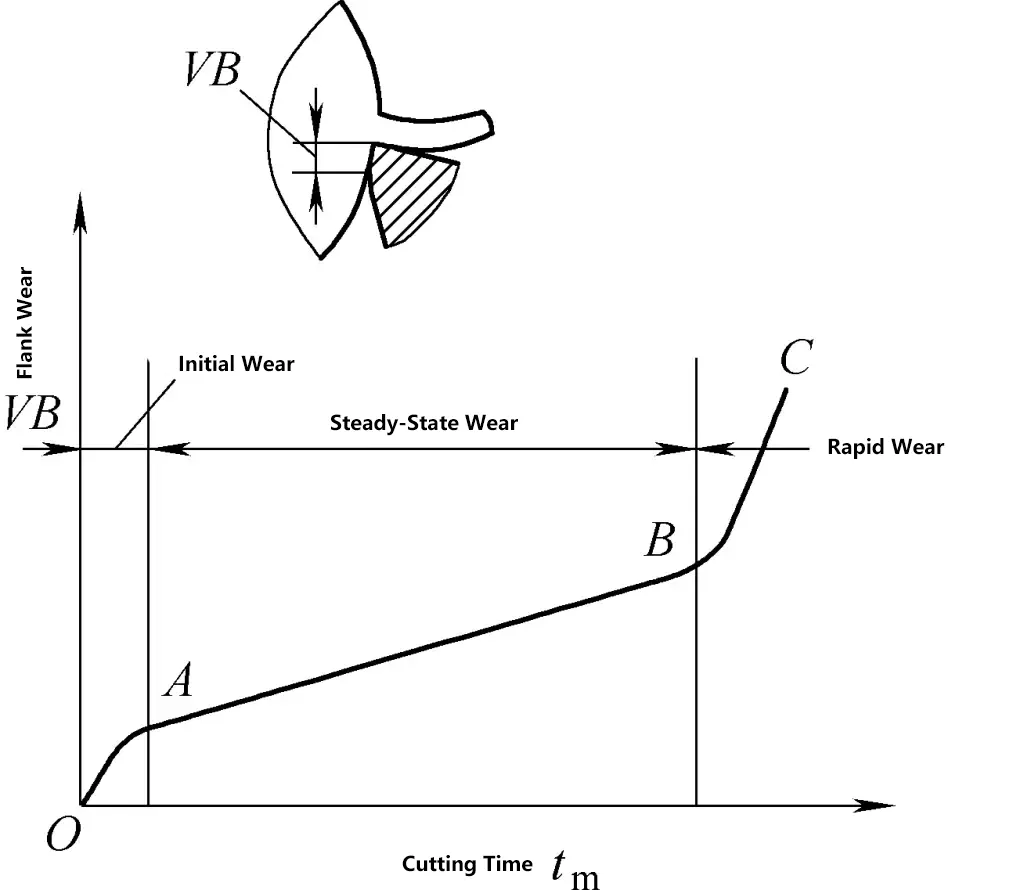
The tool wear usually refers to the wear on the flank face because in most cases, the flank face experiences wear. The size of VB has a significant impact on machining accuracy and surface roughness, and it is also more convenient to measure. Therefore, currently, the wear amount on the flank face is generally used to reflect the degree of tool wear.
(1) Initial wear stage (OA section)
The slope of the wear curve is relatively large in this stage. Due to the small actual contact area between the flank face of a newly ground tool and the machined surface, the pressure is very high, resulting in rapid wear.
The amount of initial wear is closely related to the quality of tool grinding, usually ranging from VB=0.05 to 0.1mm. Ground tools have less initial wear and are much more durable.
(2) Normal wear stage (AB section)
After the initial wear, a narrow ridge is worn on the tool’s flank face, reducing the pressure, so the increase in wear slows down and becomes more stable. This is the normal wear stage, which is also the effective working stage of the tool.
During this stage, the wear curve is basically a straight line with a small upward slope, and its slope represents the wear intensity of the tool during normal operation. Wear intensity is one of the important indicators for comparing tool cutting performance.
(3) Rapid wear stage (BC section)
After the normal wear stage, the cutting edge becomes significantly blunt, cutting forces increase, and cutting temperature rises. At this point, the tool’s wear condition undergoes a qualitative change and enters the rapid wear stage. The slope of the wear curve in this stage is very large, indicating a high wear intensity.
If the tool continues to work at this stage, it not only cannot ensure the quality of machining but also consumes more tool material and may even completely lose its cutting ability. Therefore, the tool should avoid rapid wear and avoid cutting operations in this stage.
3. Tool wear criteria
Tool wear will affect cutting forces, cutting temperature, and machining quality, so a maximum allowable wear value must be specified based on the machining conditions. This is the tool wear criteria.
Generally, there is wear on the flank face of tools, which has a more significant impact on machining accuracy and cutting forces than rake face wear. Additionally, flank face wear is easier to measure. Therefore, in tool management and metal cutting research, wear criteria are often established based on the flank face wear dimensions.
The so-called wear criteria usually refer to the maximum allowable average wear amount in the middle part of the flank wear band, expressed as VB.
For example, when rough turning carbon steel with carbide tools, VB=0.6~0.8mm; when rough turning cast iron, VB=0.8~1.2mm; for finish turning, VB=0.1~0.3mm are considered as wear criteria.
When machining large workpieces, to avoid changing tools midway, lower cutting speeds are generally used to extend tool life. In this case, the cutting temperature is lower, so the wear criteria can be appropriately increased.
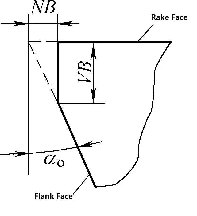
For finishing tools used in automated production, wear criteria are generally established based on workpiece accuracy requirements. In such cases, the radial wear amount NB is often used as the measurement standard, as shown in Figure 12.
4. Tool life
The cutting time from when a newly ground tool starts cutting until the wear amount reaches the wear criteria is called tool life. It is represented by T, which is the pure cutting time between two regrindings. It refers to the net cutting time and does not include non-cutting time used for tool setting, measurement, rapid feed, idle strokes, etc.
Tool life is the sum of the time a tool is used from the beginning to its disposal, i.e., the sum of the life after each regrinding. In modern production, it is not advisable to blindly pursue longer tool life. The goal should be to maximize tool life while considering product quality, production efficiency, and processing costs.
V. Methods to reduce workpiece surface roughness
Surface roughness refers to the small-spaced and tiny peak-valley unevenness on the machined surface. The distance between two peaks or two valleys (wavelength) is very small (less than 1mm) and difficult to distinguish with the naked eye, so it belongs to microscopic geometric shape errors. The smaller the surface roughness, the smoother the surface. The magnitude of surface roughness has a significant impact on the performance of mechanical parts.
The evaluation parameters for surface roughness include the arithmetic mean deviation of the profile Ra, the ten-point height of irregularities Rz, and the maximum height of the profile Ry. Since the Ra parameter can fully reflect the characteristics of the surface microscopic geometric shape in the height direction and the geometric measurement method is relatively simple, it is the most basic evaluation parameter recommended as the priority choice by standards.
The surface roughness and physical-mechanical properties of the surface layer of the machined surface are standards for evaluating the surface quality of the machined surface. Surface roughness has a significant impact on the wear resistance, corrosion resistance, fatigue strength, and fitting properties of parts. How to reduce surface roughness is also one of the important contents in cutting principle research.
1. Factors affecting workpiece surface roughness
(1) Residual area
The machined surface on the workpiece is formed by the cutting of the main and secondary cutting edges of the tool. The cross-sectional area of the part left uncut on the machined surface by the two cutting edges is called the residual area, as shown in Figure 13. From the figure, it can be seen that the larger the residual area and the higher its height, the greater the surface roughness value.
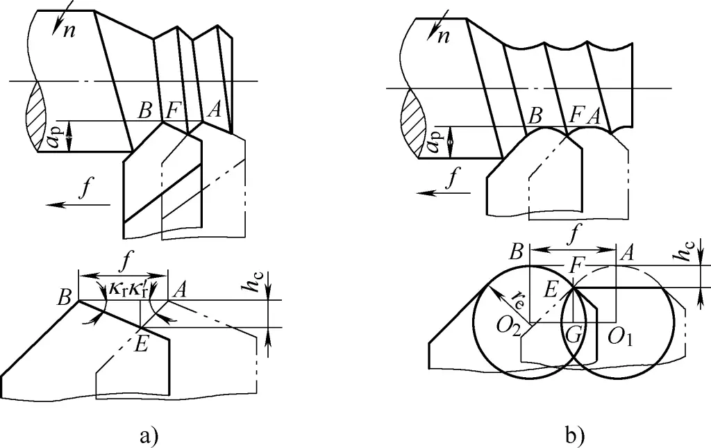
In addition, the roughness of the cutting edge also affects the machining quality of the workpiece surface. The smoother and sharper the cutting edge, the lower the surface roughness value of the machined surface.
During cutting, the plastic deformation caused by the compression and friction of the tool tip radius and the flank face will distort the residual area, thus increasing the surface roughness value of the machined workpiece surface.
(2) Scale-like burrs
When cutting plastic metals with a very small tool rake angle and a very low cutting speed, transverse cracks nearly perpendicular to the cutting speed direction and scale-like burrs, simply called scale burrs, will appear on the workpiece surface. When scale burrs appear, they can increase the surface roughness value.
(3) Built-up edge
After a built-up edge is formed when cutting plastic metals at medium speeds, because the built-up edge is both irregular and unstable, on one hand, its irregular parts replace part of the cutting edge for cutting, creating grooves of varying depths on the workpiece surface. On the other hand, some of the detached built-up edge becomes embedded in the machined surface, forming hard points and burrs, which will increase the surface roughness value of the workpiece.
(4) Vibration
Periodic vibrations produced by tools, workpieces, and machine tool components will cause periodic vibration marks on the machined surface of the workpiece, significantly increasing the surface roughness value.
2. Methods to reduce workpiece surface roughness
In cutting processes, if it is found that the surface roughness value of the workpiece does not meet the requirements of the drawing, one should first carefully observe and analyze the form and cause of the increased surface roughness value, identify the main factors affecting the increase in surface roughness value, and then propose targeted solutions.
Below are several common phenomena that cause high workpiece surface roughness values (see Figure 14).

a) High residual height
b) Surface burrs
c) Chip drag marks
d) Vibration marks
(1) Reducing residual area height
As can be seen from Figure 14, reducing the major cutting edge angle, minor cutting edge angle, and feed rate, as well as increasing the tool tip radius, can all reduce the residual area height. When implementing these, attention should be paid to the following aspects:
1) Generally, reducing the minor cutting edge angle has a more noticeable effect on reducing surface roughness values. However, reducing the major cutting edge angle k r will increase radial resistance, which may cause vibration if the technological system lacks rigidity.
2) Appropriately increasing the tool tip radius can reduce surface roughness values. However, if the tool tip radius is too large and the machine tool lacks rigidity, it will increase radial resistance and cause vibration, which in turn increases surface roughness values.
3) Reducing feed rate and increasing cutting speed can also reduce surface roughness values.
(2) Avoiding built-up edge and scratch marks
The formation of built-up edge can be suppressed by changing the cutting speed. For high-speed steel turning tools, the cutting speed should be reduced (v c <5m/min) and cutting fluid should be added; for carbide turning tools, the cutting speed should be increased (avoiding the medium speed range where built-up edge is most likely to occur, v c =15~30m/min).
Increasing the rake angle of the turning tool can effectively suppress the formation of built-up edge, but sufficient strength of the cutting edge must be ensured. Additionally, high surface roughness of the cutting edge will also cause burrs on the workpiece surface. Therefore, efforts should be made to reduce the surface roughness of the rake and flank faces, and to keep the cutting edge sharp at all times.
(3) Avoiding wear bright spots
When the tool is severely worn, bright spots or bright points will appear on the machined surface, and noise will be produced during cutting. The worn cutting edge will compress bright marks on the workpiece surface, increasing the surface roughness value. In this case, the tool should be reground or replaced promptly.
(4) Preventing chips from scratching the machined surface
The surface of workpieces affected by chip pulling will show some irregular shallow scratches on the machined surface. Selecting a cutting tool with a positive rake angle, directing the chip flow towards the unmachined surface of the workpiece, and adopting appropriate chip-breaking groove measures can effectively avoid and prevent this phenomenon.
(5) Prevent and eliminate chatter marks
Vibrations produced during turning can cause periodic transverse or longitudinal chatter marks on the workpiece surface. To address this, attention should be paid to the following aspects:
1) Machine tool aspects.
Enhance the stability of lathe installation; adjust spindle clearance, improve bearing accuracy; adjust the clearance of medium and small slide strips to less than 0.04mm, and ensure smooth and easy movement.
2) Tool aspects.
Improve tool shank rigidity; choose appropriate tool geometry parameters, and regularly maintain clean and sharp cutting edges.
3) Workpiece aspects.
Increase the mounting rigidity of the workpiece, minimize the overhang length of the workpiece; change the clamping method; use center rests or follower rests for support when working with long, slender workpieces.
4) Cutting parameters aspects.
Choose smaller depth of cut and feed rate, change or reduce cutting speed.
(6) Appropriate selection of cutting fluid, ensuring adequate cooling and lubrication
Proper selection of cutting fluid is an effective method to eliminate built-up edge, scale, and reduce surface roughness. Adequate cooling and lubrication can reduce cutting resistance, lower cutting temperature, and improve tool life.

