Gears are one of the important transmission components in mechanical transmission. Due to their accurate transmission ratio, high power transfer, high efficiency, compact structure, good reliability, and durability, they are widely used. The key to gear machining is the machining of the gear teeth. Since cutting machining can achieve higher tooth profile accuracy and smaller tooth surface roughness values, it is currently the main method of gear machining.
I. Gear Machining Principles
There are many cutting machining methods for gears, but in terms of their machining principles, there are two types: forming method and generating method.
1. Forming Method
The forming method of machining gears uses a cutter with a blade shape consistent with the cross-section of the gear tooth slot being machined, to machine the gear tooth profile on the gear blank. This type of forming cutter generally includes single-tooth profile forming milling cutters and multi-tooth profile gear hobs, gear shapers, etc.
Commonly used single-tooth profile gear milling cutters include disc-type gear milling cutters and finger-type gear milling cutters, as shown in Figure 1. Disc-type gear milling cutters are suitable for machining straight bevel cylindrical gears and helical cylindrical gears with a modulus less than 8mm.
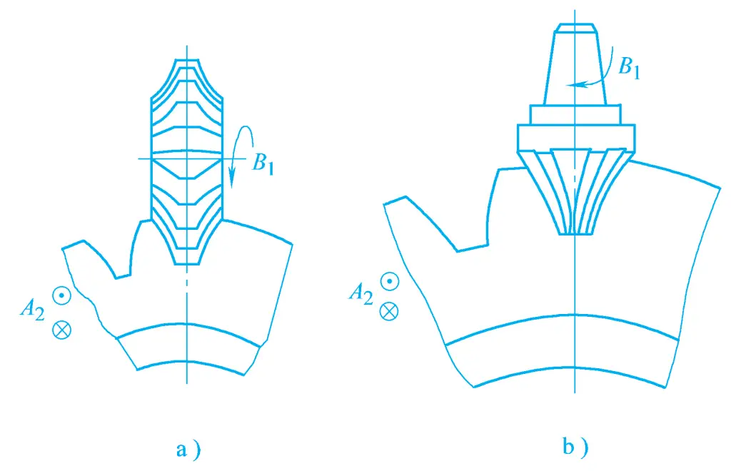
Finger-type gear milling cutters are suitable for machining straight bevel cylindrical gears, helical cylindrical gears, especially herringbone gears, with a modulus of 8~40mm. The advantage of this method is that the tools and fixtures used are relatively simple, machined on a common universal milling machine, and the production cost is low. However, since the gear tooth profile is an involute, for gears of the same modulus, as long as the number of teeth is different, their involute tooth profile shapes are not the same, requiring different forming cutters.
In actual production, each modulus usually only has a set of 8 or 15 forming milling cutters, each cutter suitable for machining a certain range of tooth numbers. Thus, the machined tooth profile is approximate, so the machining accuracy is low, and the auxiliary time for milling teeth is long, resulting in lower productivity. Therefore, using single-tooth profile forming cutters is only suitable for machining gears with precision below grade 9 in single-piece, small batch production or repair work where precision is not high.
Using multi-tooth profile forming cutters, such as gear hobs or gear shapers, the involute tooth shape of the cutter can be manufactured according to the precision of the workpiece tooth profile. During machining, one or several gear tooth profiles can be completed in one working cycle of the machine, with both precision and productivity being relatively high.
But gear hobs and gear shapers are special tools, with complex structures, difficult to manufacture, and high costs. Each set of tools can only machine gears of one modulus and one number of teeth, and the equipment used must also be specialized. Therefore, this method is only suitable for mass production.
2. Generating Method
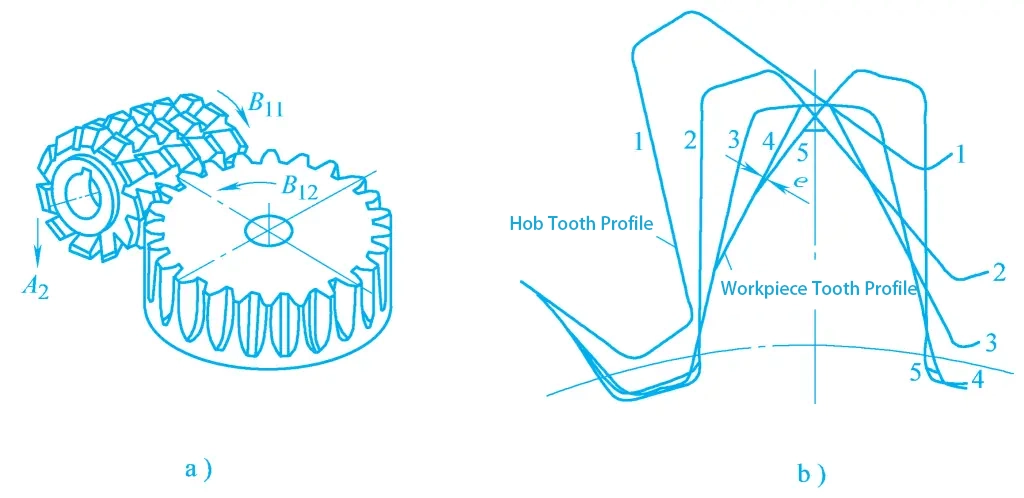
The generating method of machining gears is based on the principle of gear meshing, that is, transforming one of the gears in the gear meshing pair into a tool, treating the other as a workpiece, and forcing the tool and workpiece to perform strict meshing movement, thereby cutting out the gear tooth profile on the workpiece, this movement is called generating movement. For example, the gear hobbing process is equivalent to the process of crossed helical gear pair meshing movement, as shown in Figure 2.
a) Gear Hobbing
b) Formation of Tooth Profile Curve
In the meshing gear pair, one helical gear has very few teeth, and the helix angle on its pitch circle is also very small, so it becomes worm-shaped. After slotting, back chiseling, quenching, and grinding the worm, it becomes a gear hob.
When the gear hob moves with the given cutting speed and performs generating movement with the gear being cut, the involute tooth profile is gradually cut out on the workpiece, obviously, this tooth profile is enveloped by a series of continuous positions of the hob tooth profile during the generating movement.
When machining gears by the generating method principle, the shape of the cutting edge of the tool does not match the cross-sectional shape of the gear tooth slot being machined, and its cutting edge involute profile only relates to the number of teeth of the tool itself, unrelated to the number of teeth of the gear being machined. Therefore, if the modulus and pressure angle are the same, only one tool is needed to machine gears with different numbers of teeth.
In addition, it is also possible to machine modified gears by changing the center distance between the tool and the workpiece. The accuracy and productivity of gear machining by the generating method are both relatively high, but specialized machine tools and gear cutting tools are required. Generally, the structure of specialized gear machining machine tools is relatively complex, with many transmission mechanisms, and high equipment costs.
There are many methods for machining gears using the generating method principle, the most common being hobbing, shaping, shaving, honing, and grinding, etc. Although the tools and machine tools used in various methods are different, they can all be applied to machining high-precision gears in various types of production.
II. Gear Machining Methods and Machine Tools
1. Gear Hobbing
Gear hobbing is the most widely used method of gear machining, characterized by good versatility, high productivity, and good machining quality.
The Y3150E gear hobbing machine is a medium-sized universal gear hobbing machine, mainly used for machining straight and helical cylindrical gears, and can also use the manual radial feed method to machine worm gears. This machine tool can process gears with a maximum diameter of 500mm, a maximum width of 250mm, a maximum module of 8mm, and a minimum number of teeth of 5k (k is the number of hob heads).
Figure 3 shows the external shape of the Y3150E gear hobbing machine, which consists of main components such as the bed 1, column 2, tool slide 3, tool body 5, rear column 8, and worktable 9. The column 2 is fixed on the bed 1, and the tool slide 3 drives the tool body 5 to perform vertical feed movement or rapid movement along the column guide rail. The hob is installed on the tool bar 4, driven by the spindle of the tool body 5 to rotate as the main motion.
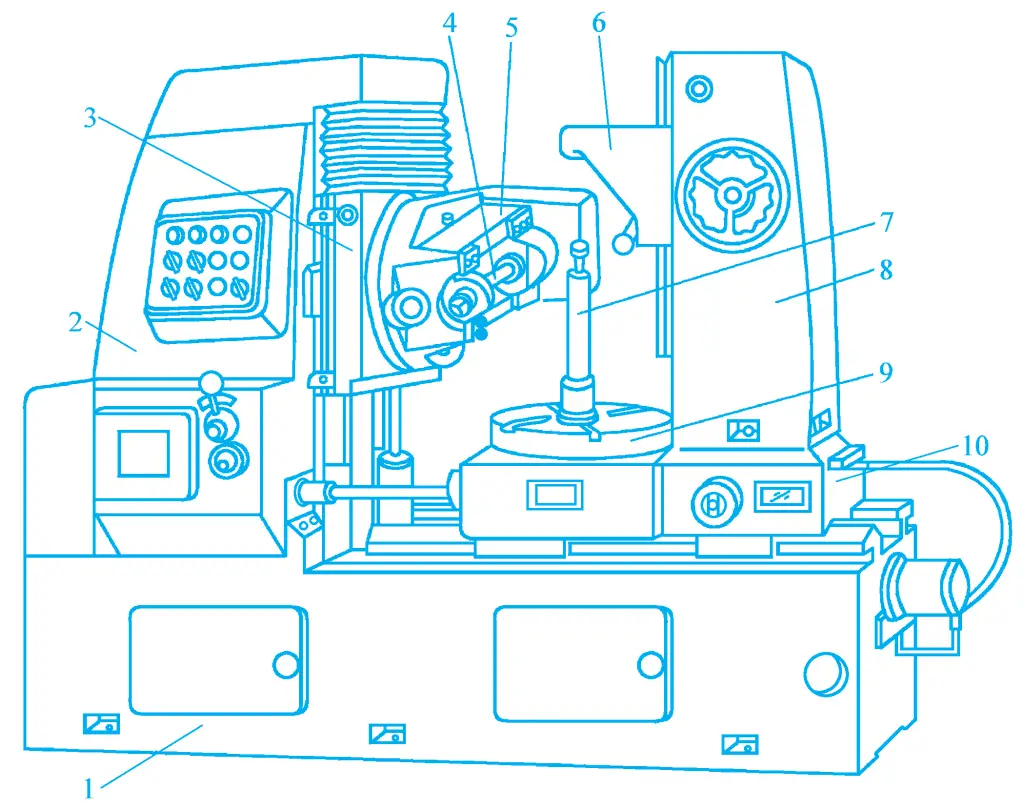
1—Bed
2—Column
3—Tool slide
4—Tool bar
5—Tool body
6—Bracket
7—Spindle
8—Rear column
9—Worktable
10—Machine saddle
The tool body can rotate around its horizontal axis to adjust the installation angle of the hob. The workpiece is clamped on the spindle 7 of the worktable 9 or directly clamped on the worktable, rotating together with the worktable.
The worktable and the rear column 8 are mounted on the machine saddle 10, which can move along the horizontal guide rail of the bed to adjust the radial position of the workpiece or perform manual radial feed movement. The bracket on the rear column can support the upper end of the workpiece spindle with a center tip or shaft sleeve to improve the stability of the hobbing work.
(1) Machining straight cylindrical gears
When machining gears with a hob according to the principle of generating method, it is necessary to strictly maintain the motion relationship between the hob and the workpiece. Therefore, the working motions of the gear hobbing machine when machining straight cylindrical gears are:
1) Main motion
It is the rotational motion of the hob n 刀 (r/min). The speed of the hob depends on the reasonable cutting speed v(m/min) and the diameter of the hob D 刀 (mm).
2) Generating motion
It is the compound motion of the rotational motion of the hob and the rotational motion of the workpiece, that is, the meshing motion between the hob and the workpiece, and the transmission relationship of a pair of meshing gears must be accurately maintained between them. Assuming the number of hob heads is k and the number of teeth on the workpiece is z, then for one rotation of the hob, the workpiece should rotate k/z turns.
3) Axial feed motion
It is the continuous feed motion of the hob along the axial direction of the workpiece, cutting out the tooth profile across the entire tooth width of the workpiece. The transmission relationship is that for one rotation of the workpiece, the hob feeds axially f(mm/r).
In addition to the above three motions, it is also necessary to manually adjust the cutting depth radially along the workpiece to cut out the full tooth height.
(2) Machining helical cylindrical gears
The tooth profile of helical cylindrical gears is a helical tooth line, so when hobbing helical cylindrical gears, in addition to the main motion, generating motion, and axial feed motion required for machining straight cylindrical gears, to form a helical tooth line, an additional motion must be made by the workpiece while the hob is making axial feed motion, and both must maintain a certain relationship, that is, as the hob moves axially the workpiece should accurately add one turn for one lead L of the helical line.
(3) Machining worm gears
Worm gears can be machined on the Y3150E gear hobbing machine using the radial feed method. Machining worm gears requires three motions: main motion, generating motion, and radial feed motion. The main motion transmission chain and generating motion are completely the same as those for machining straight cylindrical gears, and the radial feed motion can only be done manually. The module, number of heads, and pitch diameter of the worm gear hob should be the same as those of the worm.
When installing the hob, the axis of the hob should be perpendicular to the axis of the worm gear being machined and located within the central plane of the worm gear. When the worm gear hob gradually cuts in from the tooth top to the full tooth depth of the workpiece, stop the radial feed, and the workpiece continues to maintain the meshing motion with the hob and cuts for several turns to correct the tooth profile.
(4) Gear Hob
A gear hob is a worm-shaped cutter, with several grooves equally divided around its circumference, perpendicular to the worm spiral line or parallel to the axis of the hob. After the tooth profile is shaped and the back of the tooth is cut to give the correct tooth shape and back angle, followed by quenching and grinding the front, a gear hob is formed, as shown in Figure 4.
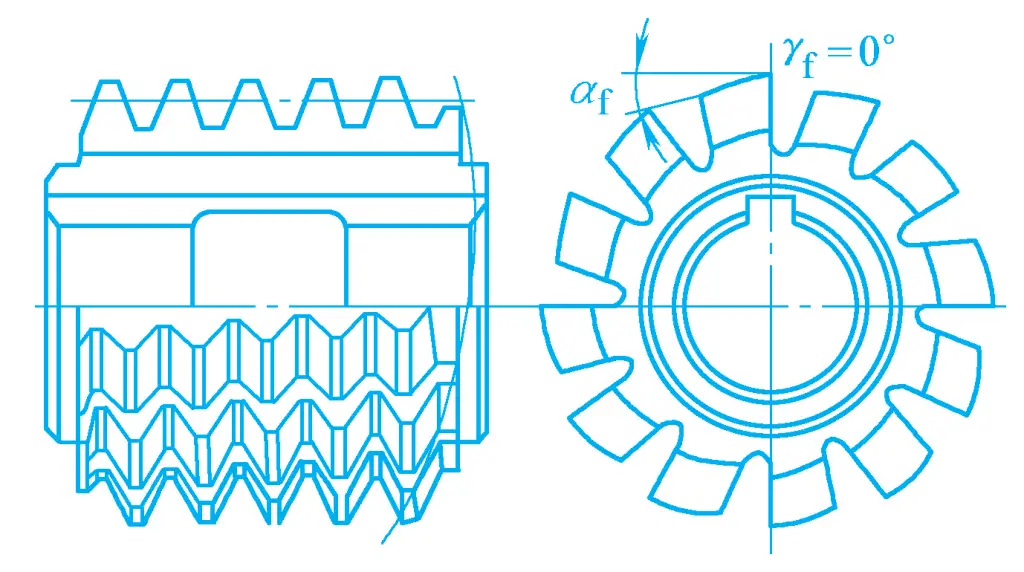
The gear hob consists of several rings of cutter teeth, each tooth having a top blade and two side blades on the left and right, both the top blade and side blades have a certain back angle. The two side blades of the cutter tooth are distributed on a helical surface, which constitutes the basic worm of the hob.
Gear hobs are divided into AA, A, B, C precision grades. Roughly, the relationship between the precision grade of the hob and the precision grade of the gear being processed is shown in Table 1, for reference when selecting a hob.
Table 1 Relationship between Hob Precision Grade and Gear Precision Grade
| Hob Precision Grade | AA | A | B | C |
| Gear Precision Grade | 6~7 | 7~8 | 8~9 | 9~10 |
When selecting a gear hob, the module and tooth profile angle of the hob should be the same as the normal module and normal tooth profile angle of the gear being processed, and its precision grade should also match the precision grade of the gear being processed.
(5) Clamping of Workpiece during Gear Hobbing
When processing gears with a small diameter, the workpiece is clamped on the mandrel by locating the inner hole, and the cylindrical body at the upper end of the mandrel is supported by the top tip or sleeve on the rear column bracket to enhance the clamping rigidity of the workpiece. When processing gears with a larger diameter, they are usually clamped with a base and mandrel with a larger end face, or the gear is directly clamped on the worktable of the hobbing machine.
(6) Characteristics of Gear Hobbing
Gear hobbing is widely used, and its main characteristics are reflected in the following aspects:
1) Good adaptability
Since gear hobbing uses the principle of generating method, one hob can process gears with different numbers of teeth that have the same module and tooth profile angle, which greatly expands the range of gear processing.
2) High productivity
Because the hob is continuously rotating during processing, performing continuous cutting on the workpiece without idle strokes, and multi-head hobs can be used to improve the efficiency of rough hobbing.
3) Small gear pitch error
During gear hobbing, several cutter teeth participate in cutting at the same time, and all the tooth slots on the workpiece are cut out by these cutter teeth, resulting in a small pitch error.
4) Rougher gear tooth surface
During gear hobbing, the workpiece turns 1 tooth, and the hob turns 1/k turn (k is the number of hob heads). Since the number of cutter teeth per circle on the hob is limited, the polyline of the tool tooth profile that forms the envelope line of the workpiece tooth profile is also very limited, much less than that of gear shaping, so the surface roughness value of the gear profile processed by hobbing is generally greater than that processed by gear shaping.
5) Mainly used for processing straight-tooth cylindrical gears, helical cylindrical gears, and worm gears
Hobbing cannot process internal gears and gears with smaller diameters in multi-gear assemblies.
2. Gear Shaping
Gear shaping is mainly used for processing straight-tooth cylindrical gears, especially suitable for processing internal gears and gears with smaller diameters in multi-gear assemblies that cannot be processed by hobbing.
The appearance of the Y5132 type gear shaping machine is shown in Figure 5. It mainly consists of the bed 1, column 2, tool post 3, spindle 4, worktable 5, saddle 7, and other components. The column is fixed on the bed, the gear shaping cutter is installed on the tool spindle, the workpiece is clamped on the worktable, and the saddle can move radially along the bed guide rail to feed the workpiece for cutting and quickly approach or retract.
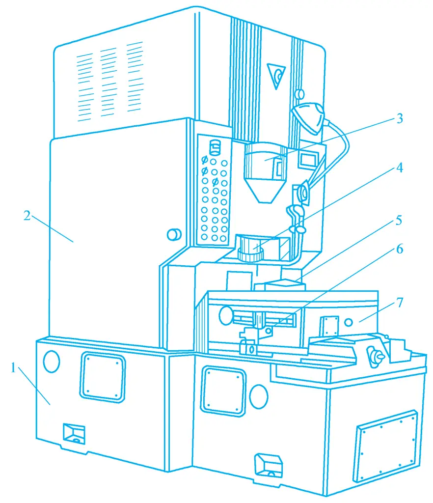
1—Bed
2—Column
3—Tool Post
4—Main spindle
5—Workbench
6—Stop block bracket
7—Bed saddle
(1) The motion of gear shaping
Gear shaping is based on the principle of generating method. The gear shaping cutter is essentially a gear with its end face ground with a front angle, and both the top and sides of the teeth ground with a back angle, as shown in Figure 6a. During gear shaping, the gear shaping cutter and the workpiece engage in a gapless meshing motion, gradually cutting out the tooth shape on the workpiece. The tooth profile curve is formed by the envelope of the instantaneous positions of the cutting edge during multiple cuts by the gear shaping cutter, as shown in Figure 6b.
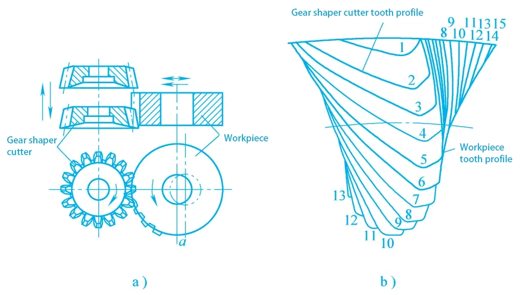
a) Gear shaping
b) Formation of the tooth profile curve
Motions required for machining straight bevel cylindrical gears:
1) Main motion
The main motion in gear shaping is the reciprocating linear motion made by the gear shaping cutter along the axial direction of the workpiece. The downward motion of the gear shaping cutter is the working stroke, and the upward motion is the idle stroke. The main motion is represented by the number of reciprocating strokes per minute, i.e., reciprocating strokes/min.
2) Generating motion
During gear shaping, the gear shaping cutter and the workpiece must maintain a gapless meshing motion relationship as a pair of cylindrical gears. When the gear shaping cutter turns one tooth, the workpiece must also turn one tooth. The meshing rotary motion made by the gear shaping cutter and the workpiece is called generating motion.
3) Circular feed motion
Circular feed motion is the rotational motion of the gear shaping cutter around its own axis. The speed of rotation determines the speed of rotation of the workpiece, and also affects the cutting load of the gear shaping cutter, the surface quality of the workpiece, the productivity of machining, and the life of the gear shaping cutter. The circular feed amount is represented by the arc length turned by the gear shaping cutter on the pitch circle for each reciprocating stroke, in units of mm/per double stroke.
4) Radial infeed motion
To avoid damage to the tool and workpiece due to excessive cutting load, the workpiece should gradually make a radial infeed towards the gear shaping cutter. When the workpiece is cut to full tooth depth by the gear shaping cutter, the radial infeed motion stops, and the workpiece rotates once more to produce a complete tooth profile. The radial feed amount is represented by the distance of radial infeed of the workpiece for each reciprocating stroke of the gear shaping cutter, in units of mm/per double stroke.
The radial infeed motion of the Y5132 gear shaping machine is achieved by moving the workpiece towards the gear shaping cutter driven by the workbench. During machining, the workbench moves quickly a greater distance to bring the workpiece close to the tool, and then starts the radial infeed. When the machining of the workpiece is completed, the workbench quickly returns to its original position.
5) Tool retraction motion
When the gear shaping cutter moves upward during the idle stroke, to avoid scratching the surface of the workpiece and reduce tool wear, there should be a gap of about 0.5mm between the tool and the workpiece. Before the gear shaping cutter starts the downward working stroke, it quickly returns to its original position to allow the tool to make the next cut. This motion of retracting and returning to the original position is called tool retraction motion. This machine tool achieves tool retraction motion through the swinging of the tool spindle.
(2) Gear shaping cutter
There are mainly three types of straight-tooth gear shaping cutters used in gear shaping: disc-type straight-tooth gear shaping cutter, bowl-type straight-tooth gear shaping cutter, and taper shank straight-tooth gear shaping cutter, as shown in Figure 7.
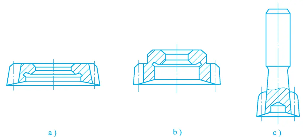
a) Disc-type straight-tooth gear shaping cutter
b) Bowl-type straight-tooth gear shaping cutter
c) Taper shank straight-tooth gear shaping cutter
The disc-type straight-tooth gear shaping cutter is positioned by the inner hole and the supporting end face, and is fastened to the machine spindle with a nut. It is mainly used for machining straight-tooth external gears and large diameter straight-tooth internal gears. Its commonly used pitch circle diameters are four types: 75mm, 100mm, 160mm, 200mm, suitable for machining gears with a module of 1~12mm.
The bowl-type straight-tooth gear shaping cutter is mainly used for machining multi-link gears and gears with convex shoulders. This type of gear shaping cutter is positioned by its inner hole, and the clamping nut can be accommodated inside the cutter body. The commonly used pitch circle diameters are also four types: 50mm, 75mm, 100mm, 125mm, suitable for machining gears with a module of 1~8mm.
The taper shank straight-tooth gear shaping cutter is an integral structure with a taper shank (Morse taper shank) and is connected to the machine spindle with a special connector with an internal taper hole. It is mainly used for machining straight-tooth internal gears. The nominal pitch circle diameters are two types: 25mm and 38mm, suitable for machining gears with a module of 1~3.75mm.
There are generally three precision grades for gear shaper cutters: AA, A, and B, which are used under normal processing conditions to process gears of precision grades 6, 7, and 8, respectively.
(3) Characteristics of gear shaping
1) High tooth profile accuracy
The teeth of a gear shaper cutter can be ground by a high-precision gear grinding machine to obtain an accurate involute tooth profile, thus the processed tooth profile has high accuracy.
2) The obtained tooth profile surface roughness value is relatively small
During gear shaping, the gear shaper cutter continuously cuts chips along the full length of the gear, while during gear hobbing, the hob cutter cuts out a small section of the tooth profile in the direction of the gear length each time, and the entire tooth length is formed by the hob cutter cutting intermittently multiple times. Therefore, gear shaping achieves a smaller surface roughness value than gear hobbing.
3) Conducive to improving the accuracy of the tooth profile and reducing the surface roughness value
During gear shaping, by reducing the circumferential feed amount and increasing the number of broken lines forming the involute tooth profile envelope, the accuracy of the tooth profile and the surface roughness value are improved. During gear hobbing, the involute of the same tooth profile of the workpiece is enveloped by a smaller number of broken lines, thus the tooth profile accuracy is not high, and the surface roughness value is larger.
4) The change in the common normal length of the workpiece is relatively large
During gear shaping, due to the presence of pitch errors of the gear shaper cutter itself, installation errors of the gear shaper cutter, and cumulative pitch errors of the worm wheel driving the gear shaper cutter to rotate on the gear shaping machine, there will be a relatively large angular error when the gear shaper cutter rotates. Therefore, the change in the common normal length of the gears processed by gear shaping is larger than that of the gears processed by gear hobbing.
5) Low productivity
During gear shaping, since the tool moves in a straight reciprocating motion, the increase in cutting speed is limited, and there is idle travel. Therefore, under general conditions, the productivity of gear shaping is lower than that of gear hobbing.
6) Machining helical gears is very inconvenient, and worm gears cannot be machined
It is very inconvenient for a gear shaping machine to machine helical cylindrical gears, requiring the replacement with inclined guide rails and long auxiliary time. Additionally, gear shaping machines cannot machine worm gears.
3. Other gear machining methods
For gears with a precision grade above 6, rough machining is often performed first using gear hobbing or shaping, followed by fine machining of the tooth surface. For the machining of hardened gear surfaces, heat treatment is often performed after hobbing or shaping, followed by fine machining of the tooth surface. Common fine machining methods for tooth surfaces include shaving, honing, and grinding.
(1) Gear shaving
Gear shaving is commonly used for the fine machining of the tooth profile of unhardened cylindrical gears, with high productivity, and is widely used in batch production.
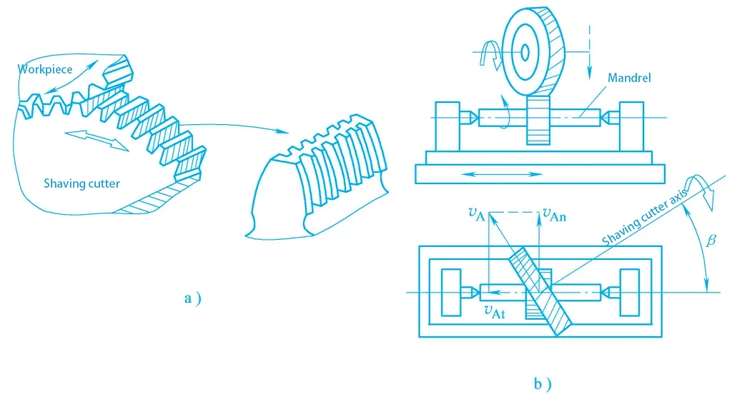
Gear shaving also belongs to the generating process. The generating motion of gear shaving is equivalent to the meshing of a pair of crossed-axis helical cylindrical gears, and the gear shaving cutter is essentially a high-precision helical gear. Small grooves are opened along the involute direction on its tooth surface, and the side surfaces of these small grooves form the cutting edges of the gear shaving cutter, as shown in figure 8a.
a) Gear shaving cutter
b) Gear shaving process illustration
During gear shaving, the workpiece is first clamped on the center axis between the two centers on the machine tool, and then the gear shaving cutter is installed on the main spindle of the machine tool, driven by the main spindle to rotate, realizing the main motion. The axis of the gear shaving cutter forms an axis crossing angle β with the axis of the workpiece, the workpiece meshes with the gear shaving cutter under a certain pressure, and is driven to rotate by the gear shaving cutter, performing a gapless free meshing motion with the gear shaving cutter, as shown in figure 8b.
Since the gear shaving cutter and the workpiece are equivalent to the meshing of a pair of crossed-axis helical cylindrical gears, the direction of velocity at the meshing point is inconsistent, causing relative sliding along the tooth length direction between the gear shaving cutter and the workpiece tooth surface. This sliding velocity is v0 = v1 sinβ, which is the cutting speed of gear shaving. Due to the presence of this speed, the gear shaving cutter’s cutting edge can cut off micro-fine chips from the workpiece tooth surface, achieving fine machining of the workpiece tooth surface.
To achieve the same shaving effect on both sides of the workpiece tooth profile, the gear shaving cutter should alternately change the rotation direction during the shaving process. During gear shaving, to shave the full tooth length of the workpiece, the worktable must perform a longitudinal straight reciprocating motion.
After each unidirectional travel of the worktable, the gear shaving cutter reverses, the worktable moves in the opposite direction, shaving the other side of the gear. After the double-direction travel of the worktable, the gear shaving cutter performs an intermittent radial feed once, gradually shaving off the excess material on the tooth surface, ultimately meeting the drawing requirements.
Gear shaving has the following characteristics:
1) High efficiency, low cost
Generally, the machining of a gear only takes 2~4min, and the cost is on average 90% lower than that of gear grinding. Gear shaving is suitable for the fine machining of the tooth profile of unhardened gears.
2) Poor correction ability for tangential errors of gears
In terms of process arrangement, it is more appropriate to use gear hobbing as the preceding process to gear shaving, because the motion accuracy of gears processed by hobbing is higher than that of gears processed by gear shaping. Although the gear shape error of gears processed by hobbing is larger than that of gears processed by shaping, this is not difficult to correct in gear shaving.
3) Conducive to improving the accuracy of gear tooth profile
This is because gear shaving has a strong correction ability for gear tooth profile errors and pitch errors. As long as the shaving cutter itself has high precision and the grinding quality is good, it can shave gears with a surface roughness value of Ra1.25~0.32μm and precision up to grade 7~6.
(2) Honing gear processing
Honing gear processing is one of the methods for fine processing of hardened gear profiles, mainly used to remove the oxide layer on the tooth surface after heat treatment, reduce the surface roughness of the gear teeth, thereby reducing the noise of gear transmission.
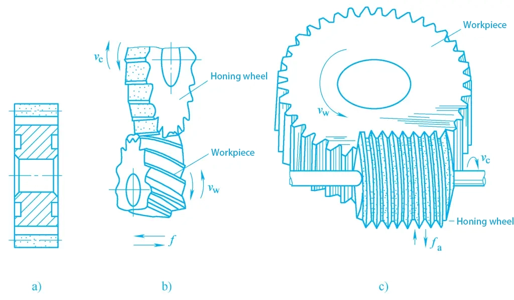
The tool used for honing gears is a honing wheel, also known as a honing ring, which consists of a wheel blank and a tooth ring, as shown in figure 9a. The wheel blank is made of steel, and the tooth ring part is cast or hot-pressed with abrasives (aluminum oxide, silicon carbide), binder (epoxy resin), and curing agent (ethylenediamine), its structure is similar to that of grinding tools, only that the cutting speed of honing is much lower than that of grinding, but higher than that of shaving.
a) Honing wheel
b) Schematic of honing gear processing
c) Worm-shaped honing wheel honing gear
The motion of honing gears is the same as that of shaving gears. During honing gear processing, the honing wheel and the workpiece are in free meshing, relying on the pressure and relative sliding between the tooth surfaces, cutting is performed by the abrasive, as shown in figure 9b.
In mass production, worm-shaped honing wheels are widely used for honing gears, as shown in figure 9c. The honing wheel is a large diameter worm, with a diameter of 200~500mm, and its tooth profile can be precision ground to above grade 5 accuracy on a thread grinding machine.
Due to its high tooth profile accuracy and high honing speed, its ability to correct workpiece errors is enhanced, especially for workpiece tooth profile errors, pitch deviations, and radial runout errors of the tooth ring can all be corrected to a certain extent. Honing gear processing can directly hone gears from grade 9~8 precision to grade 6 precision, possibly eliminating the pre-honing shaving process.
Honing gear processing has the following characteristics:
1) Good surface quality
During honing, due to the low cutting speed, the processing process is a combination of low-speed grinding, lapping, and polishing, the workpiece being honed will not produce burns and cracks, the surface quality is very good, with a surface roughness value of Ra1.25~0.16μm.
2) Poor error correction ability
Because the honing wheel is highly elastic and the machining allowance is small, only 0.025mm, and the abrasive grain size is large, the error correction ability of honing gears is worse than that of grinding gears. However, the error of the honing wheel itself has little impact on machining accuracy. Before honing, gear processing should preferably use hobbing, which has higher motion accuracy than shaping, thereby reducing the correction requirements for cumulative pitch errors, etc.
3) The modeling accuracy of the honing wheel
High The tooth profile of the honing wheel is simple, making it easy to achieve high modeling accuracy.
4) High productivity, long service life of the honing wheel
The efficiency of honing gears is generally 10~20 times that of grinding gears, and the tool life is very high, with the honing wheel being able to hone 60~80 gears after each dressing.
(3) Gear grinding processing
Gear grinding processing is mainly used for the precision machining of high-precision gears or hardened gears, with the precision of gears reaching grade 6 or higher. According to the method of forming the tooth profile, gear grinding processing methods also include the generating method and the form grinding method. Since the precision of gears ground by the form grinding method is lower, most gear grinding is done using the generating method. There are several methods for generating method gear grinding.
1) Generating method gear grinding methods
Generating method gear grinding mainly includes continuous indexing generating method and single tooth indexing generating method.
Continuous indexing generating grinding of teeth. Continuous indexing generating grinding is the process of grinding the teeth of gears with a worm-shaped grinding wheel, which is similar to the process of gear rolling, as shown in Figure 10.
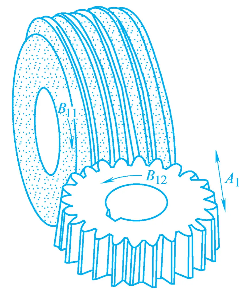
The rotational motion B₁₁ of the worm-shaped grinding wheel is the main motion, the rotational motion B₁₂ of the workpiece meshing with the grinding wheel is the generating motion, and the axial feed motion A₁ is generally completed by moving the workpiece up or down. Since the worm-shaped grinding wheel continuously grinds the tooth profile of the workpiece during the processing, its productivity is the highest among all gear grinding methods.
The disadvantage of this gear grinding method is that it is difficult to re-sharpen the worm-shaped grinding wheel, often not achieving high precision. When grinding gears of different modules, it is necessary to change the worm-shaped grinding wheel. In addition, the transmission parts of the equipment used have very high speeds, mechanical transmission can easily produce noise, and the transmission parts wear out quickly. This method of gear grinding is suitable for batch and mass production of medium and small module gears.
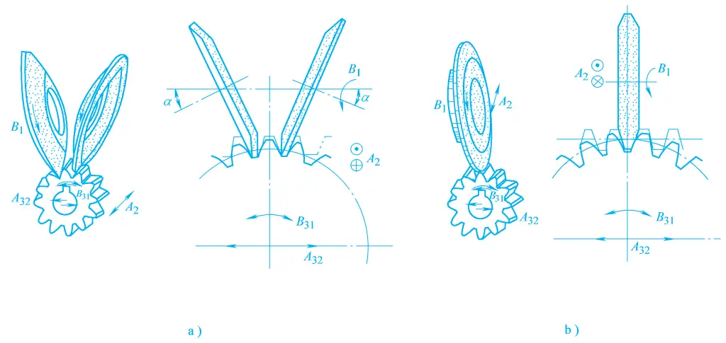
Single tooth indexing generating grinding of teeth. Single tooth indexing generating grinding can be performed using different shapes of grinding wheels, such as disk-shaped grinding wheels, cone-shaped grinding wheels, etc., as shown in Figure 11. Their grinding processes all utilize the principle of meshing between the rack and the gear to grind the gear.
2) Characteristics of gear grinding processing
The main characteristic of gear grinding processing is that it can produce gears of high precision. Under general conditions, the precision of the processed gears can reach level 6 to 4, and the surface roughness can reach Ra0.8 to 0.2μm. Because gear grinding processing adopts the forced meshing motion of the grinding wheel and the workpiece, it not only has a strong ability to correct gear errors but is also particularly suitable for processing gears with very high tooth surface hardness.
However, except for worm-shaped grinding wheel gear grinding, the efficiency of general gear grinding processing is relatively low, the equipment structure is relatively complex, adjusting the equipment is difficult, and the processing cost is high. Currently, gear grinding is mainly used for processing gears with very high precision requirements, especially gears with hard tooth surfaces.

