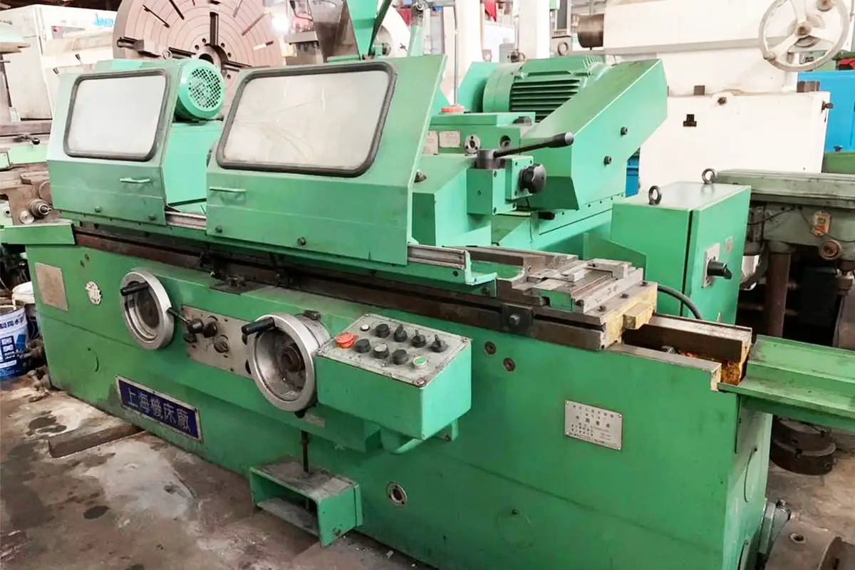
I. Selection of foundation for cylindrical grinding machines
Grinding machines are precision machine tools, and the selection and construction of their foundation have a significant impact on the grinding performance of the machine.
1. Principles for selecting the foundation
When choosing the location for the grinding machine foundation, in addition to considering the convenience of the process flow and rationally designing the workshop layout, the following principles should also be noted:
1) No vibrating machines should be installed near the machine tool, especially far from equipment with severe impacts, such as forging, shearing machines, and planers (if it cannot be far from vibration sources due to special reasons, then coal cinder, cork board, etc. should be used for isolation around the foundation, generally the isolation layer thickness should not be less than 150mm).
2) The machine tool should not be exposed to direct sunlight to prevent the influence of various radiant heat sources.
3) The machine tool should be installed on a flat and solid foundation. If the workshop floor is solid and surrounded by precision machine tools, a separate foundation may not be necessary.
4) When determining the foundation dimensions, in addition to the specific dimensions specified in the manual, the maximum displacement dimensions of the moving parts of the machine tool (including the opening dimensions of various doors and covers, the range of cutting fluid tank movement), the placement of accessories and workpieces, as well as the maintenance space for the machine tool should be considered.
For the selection of high-precision cylindrical grinding machine foundations, in addition to complying with the above principles, further active anti-vibration measures should be taken, and requirements for constant temperature and environmental cleanliness should be met.
2. Construction of the foundation
When constructing a separate foundation, it is made of integral concrete (the strength grade of cement should not be lower than 42.5).
The depth indicated on the foundation drawing in the manual is the minimum value for normal solid soil conditions. For relatively loose soil, the foundation depth should be appropriately increased. Especially in cases where the foundation soil is sand, river marsh, or newly filled soil, pile foundations should be added and filled with stones. After the foundation curing period is over, a weight equivalent to twice the mass of the machine tool should be evenly pressed on the foundation (for at least seven days) to stabilize its compression settlement and inclination before starting to build the machine tool foundation.
For the pre-embedded cable locations in the foundation, it is recommended to use galvanized steel pipes with better corrosion resistance. The top of the pipe should be about 100mm above the foundation surface, while the lower end is buried in the foundation.
When the machine tool still needs to be fixed with anchor bolts, grouting holes should be reserved. Grouting can be done during machine installation. The foundation should have a 28-day curing period after pouring, and should be kept moist by frequent watering during the first week.
If construction is done in winter, the curing period should be appropriately extended and anti-freezing measures should be taken (installation of the machine tool is not allowed during the curing period). For machine tools fixed with anchor bolts, after rough leveling, fill the reserved anchor bolt grouting holes with 1:3 cement mortar. After three to seven days, fine-tune the installation level and tighten the anchor bolts.
For machine tools with larger beds, it is allowed to not fully fill the gap between the shims and the foundation with cement mortar, but the periphery of the bed still needs to be blocked with wooden boards or cement fillers to prevent accidental movement of the shims.
II. Installation methods for cylindrical grinding machines
1. Tightening of anchor bolts
Generally speaking, due to the small grinding force and low vibration during the grinding process, the bed does not need to be fixed with anchor bolts after being placed on the foundation.
However, for some extra-long beds, beds composed of several sections, or large grinding machines that easily produce vibrations and affect machine precision when grinding discontinuous surfaces, anchor bolts must be tightened. In this case, the following requirements should be met:
1) Before tightening the anchor bolts, adjust the bed level according to the specifications, or verify that the machine precision meets the standards and make actual measurement records.
2) After evenly tightening the anchor bolts, check the machine level or various precision actual measurement results, which should be as consistent as possible with the previous actual measurement records (even for long beds composed of multiple sections, deformation should be minimized).
3) After use or conducting operational and load tests, the bed level or various precision measurements should still meet standards before loosening the anchor bolts.
4) Once it is necessary to loosen the anchor bolts, it is permissible to make the machine precision meet standards through normal adjustment of the installation level.
2. Use of shims
(1) Types of shims
Shims are commonly used tools for adjusting the installation level of machine tools and can also be used to adjust machine precision. They are placed between the bottom surface of the machine tool and the foundation during use.
Figure 1 shows an inclined movable shim, suitable for machine tools not exceeding 20t. This type of shim has many longitudinal and transverse semi-circular grooves on the bottom surface of the base 1, which can prevent movement. During adjustment, the adjustment screw 2 and a 1:10 inclined surface are used to raise or lower the machine tool.
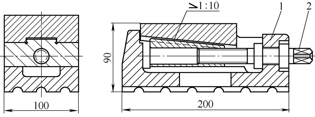
1—Base
2—Adjustment screw
Figure 2 shows a screw-top column type shim, suitable for small and high-precision grinding machines. This type of shim has a simple structure, with the lower end of screw 1 forming a hemispherical indentation in shim 4. Adjusting screw 1 can raise or lower the bed.
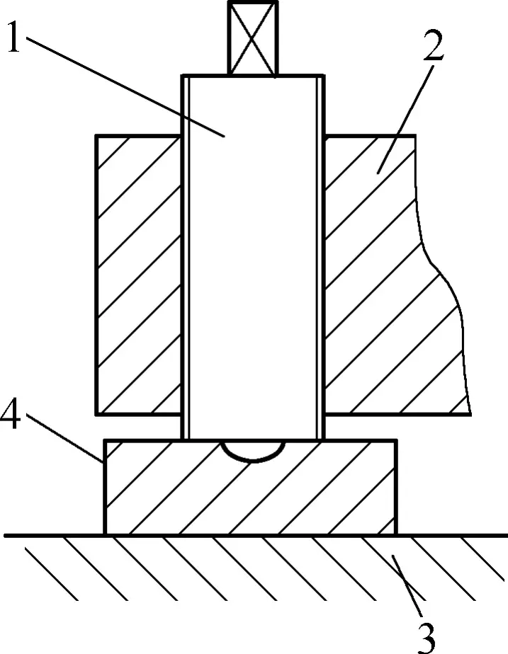
1—Screw
2—Bed
3—Foundation
4—Shim
It should be noted that when using shims, the method of directly hammering inclined wedges for installation adjustment should not be adopted.
(2) Layout and adjustment of machine tool shims
Generally, machine tool shims are divided into main shims (indicated by ● symbol in Figure 3), auxiliary main shims (indicated by ◎ symbol in the figure), and auxiliary shims (indicated by ○ symbol in the figure). The positions of the shims can be placed according to the foundation drawing in the machine manual, but the placement and adjustment sequence should be carried out according to the following method.
1) Preliminary adjustment of installation level. Generally, only main shims need to be placed (main shims are usually composed of three pieces).
When adjusting the bed level, first adjust the A and B shims that determine the longitudinal level of the bed, then adjust the C shim that affects the transverse level of the bed. However, as shown in Figure 3a, when the bed has only four shims, it is generally adopted to first add an auxiliary main shim C (indicated by the ◎ symbol in Figure 3a) for rough leveling, then add auxiliary shims and remove the auxiliary main shim to adjust the level.
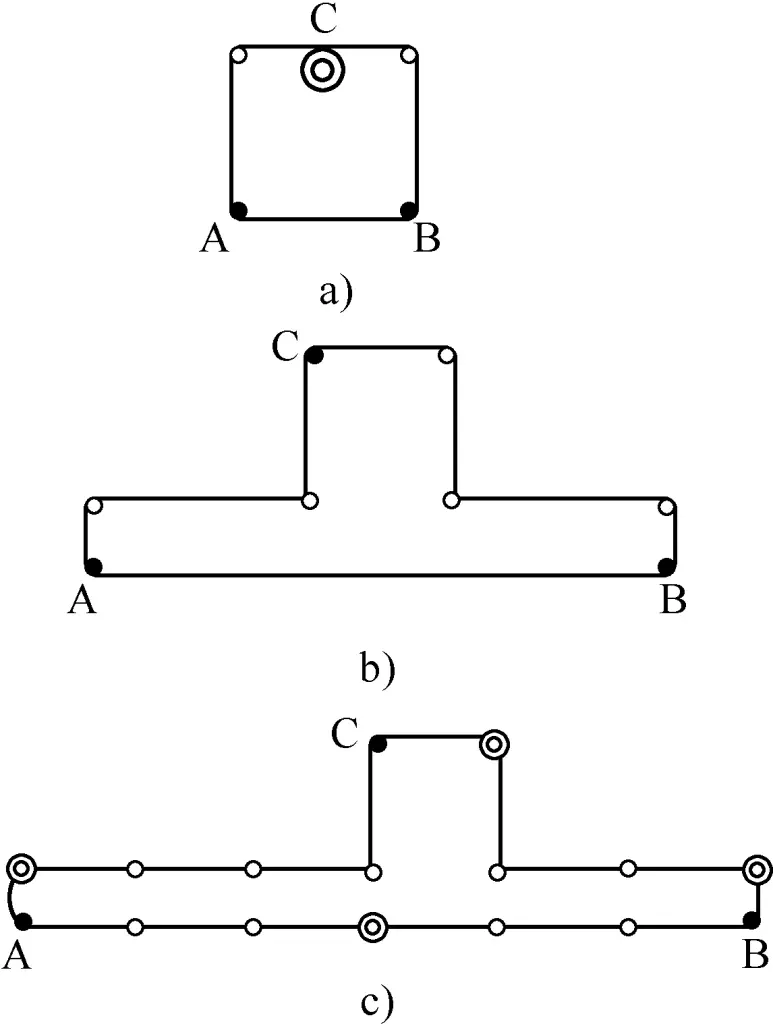
When leveling spliced or long beds, in addition to first placing three main shims, 3-5 auxiliary main shims need to be placed simultaneously to avoid deformation of the bed during the rough leveling process, as shown in 3c.
2) When precisely adjusting the installation level, the remaining auxiliary shims should be placed according to the positions shown in the machine foundation drawing. The adjustment of each auxiliary shim should ensure that it does not affect the already preliminarily adjusted machine level values (but it is allowed to adjust the various precision values of the machine guide rails through the placement of auxiliary shims).
All adjusted machine tool shims should preferably not be able to be pulled by hand (pulling force of 100-150N).
3. Adjustment of installation level
The installation level of cylindrical grinding machines is closely related to the geometric precision and grinding performance of the machine tool.
Improper installation of the machine tool can cause uneven slow movement of the worktable, and for grinding wheel carriages with rolling guides, it often leads to unstable rapid positioning accuracy. Therefore, before measuring various precision aspects of the machine tool and starting it up, the installation level of the machine tool must first be adjusted using shims.
There are many methods for adjusting the installation level, including adjusting on the worktable or special bridge plate, as well as adjusting on the bed guide rails.
(1) Measurement methods for transverse level
1) For cylindrical grinding machines with generally transverse rolling guides, since wooden boards are placed on the transverse guides during packing and shipping (with roller plates removed), users need to lift the grinding wheel carriage when installing the machine tool (when lifting the carriage, care should be taken to disconnect the electrical wires and oil pipes connecting it to the bed to avoid breaking them). At this time, remove the wooden boards placed on the guide rails, and a spirit level can be placed in the middle of the flat guide rail, with its reading being the transverse installation level.
To obtain a more accurate transverse installation level, the spirit level can be placed in the middle and at both ends of the flat guide rail, taking the average of their readings.
2) For machine tools that do not require lifting the grinding wheel carriage or where conditions do not allow lifting the grinding wheel carriage, a measuring device can be placed on the machine worktable (a straightedge for flat worktables, a special bridge plate for inclined worktables), with a spirit level placed transversely in the center of the measuring device. The reading of the spirit level minus the parallelism of the measuring device itself and the worktable to the transverse guide rail is the transverse level error.
Note: The parallelism of the measuring device itself and the worktable to the transverse guide rail can be obtained by fixing a dial indicator on the grinding wheel carriage, moving the carriage throughout its range to measure the upper surface of the measuring device, and calculating the maximum difference converted to an angular deviation, which is the parallelism of the measuring device itself and the worktable to the transverse guide rail.
(2) Several measurement methods for longitudinal level
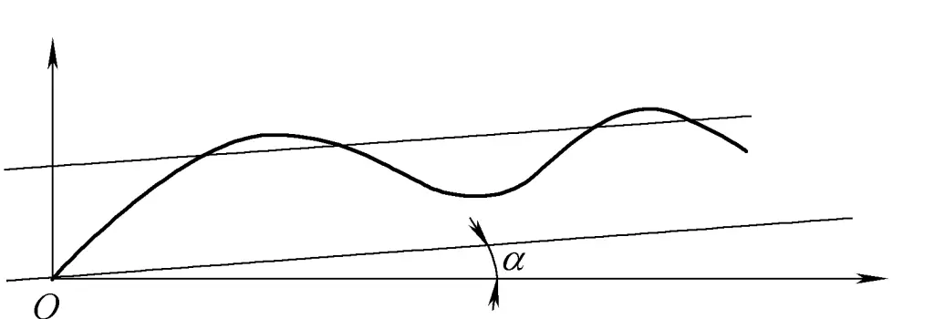
1) In the manufacturing plant or for users with the necessary conditions, to accurately determine the longitudinal installation level, the tangent of the angle α between the envelope line of the measured motion curve of the longitudinal guide rail in the vertical plane and the horizontal axis line can be used as the longitudinal installation level error (see Figure 4). For details on the motion curve and envelope line of the guide rail, see the later discussion.
2) When the precision of the bed’s longitudinal guide rail is verified to be acceptable, the spirit level can be placed directly on the flat guide rail to obtain the longitudinal installation level value.
① For shorter beds, the spirit level can be placed directly in the middle of the flat guide rail, and its reading is the longitudinal installation level.
② For beds of general length, the spirit level can be placed at both ends of the flat guide rail, and the average of the algebraic sum of the two readings is the longitudinal installation level.
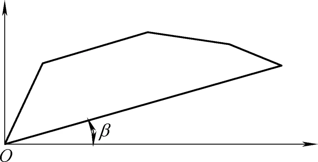
③ For longer beds (length > 3m), the spirit level can be placed on the flat guide rail at certain measurement intervals, and the average of the algebraic sum of each reading is the longitudinal installation level. Alternatively, a graphical method can be used, where the tangent of the angle β between the line connecting the readings at both ends and the horizontal axis line is the longitudinal installation level error, as shown in Figure 5.
3) In cases where lifting is inconvenient, users can also remove the guards at both ends of the worktable, move the worktable to the right end, and place the spirit level on the exposed part of the left flat guide rail; then move the worktable to the left end and place the spirit level on the exposed part of the right flat guide rail. If conditions permit, measure at multiple positions at both ends with the spirit level, and the average of the algebraic sum of each reading is the longitudinal installation level error.
For grinding machines with shorter beds or when conditions do not allow for lifting the worktable, the only option is to place measuring instruments on the worktable (a straight edge for flat worktables, or a special bridge plate for inclined worktables). A spirit level is then placed horizontally in the center of the measuring instrument. The reading on the spirit level, minus the parallelism of the measuring instrument itself and the worktable to the transverse guide rails, gives the transverse horizontal error. (Note: The method for measuring the parallelism of the measuring instrument itself and the worktable to the transverse guide rails is the same as the method described for measuring the transverse installation level.)
Generally, special bridge plates or straight edges are manufactured accurately and parallel to the machine’s transverse and longitudinal guide rails. However, due to imperfect parallelism in manufacturing and machine deformation, there are always transfer errors. Therefore, this method should only be used when unavoidable or when the leveling requirements are not high.
III. Measurement of Grinding Machine Guide Rail Accuracy
Currently, grinding machine guide rails are divided into longitudinal and transverse types. The longitudinal guide rails refer to those between the worktable and the bed, while the transverse guide rails are those between the grinding wheel carriage and the lower saddle.
Since the straightness of the ground workpiece is directly related to the accuracy of the longitudinal guide rails, generally, except for precise measurement and adjustment at the manufacturing plant before assembly, users can also measure and adjust according to the methods described in this chapter if there are high requirements for workpiece straightness or when the machine is undergoing maintenance.
1. Instruments for Measuring Guide Rails and Their Use
(1) Types of Instruments
1) Square frame spirit level (or long ruler spirit level): Square frame lengths come in 200mm, 250mm, and 300mm. It is recommended to use a spirit level with a measurement accuracy of 0.02mm/m per division.
2) Coincidence spirit level: Its measurement accuracy is 0.01mm/m per division.
3) Autocollimator (optical straightness tester): Its measurement accuracy is 0.005mm/m per division.
(2) Some Knowledge About Spirit Levels
As shown in Figure 6a, assuming the guide rail surface is naturally level and straight, when a 1m long straight edge is placed on the guide rail surface, the spirit level reading on the straight edge will be “0”. As shown in Figure 6b, if the right end of the guide rail surface rises (is not straight) by 0.02mm at 1000mm, and if the measurement accuracy of the spirit level on the straight edge is 0.02mm/m, then the bubble will move exactly one division.

Based on trigonometry, it can be clearly calculated that when the bubble moves one division, the rise within the length of the spirit level (within 250mm length) is 0.005mm. This concept is the basis for drawing the motion curve of the guide rail when measuring guide rail accuracy using a spirit level.
(3) Use of the Autocollimator
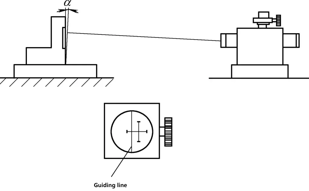
The principle of the autocollimator is that a parallel light beam with a “cross” is emitted from a light source. If the reflecting mirror surface is perpendicular to the parallel light, the reflected “cross” projection will coincide with the reference line. When the guide rail surface is not straight, causing the reflecting mirror to tilt by an angle α, the “cross” projection will deviate from the reference line. By turning the knob, the “cross” can be adjusted to coincide with the reference line. At this time, the change in the scale reading on the knob is the error value.
Generally, 1 division on the autocollimator scale represents α=1°. Since tan1°=0.005/1000=0.001/200, when the length of the measuring instrument is 200mm, a reading of 1 division on the autocollimator means the error coordinate value of the measured surface is 0.001mm.
In Figure 7, the α reading reflects the angular error value of the guide rail in the vertical plane. To measure the angular error value in the horizontal plane, the top screw of the autocollimator’s measuring eyepiece can be loosened, rotated 90°, and then the corresponding angular error value can be read using the same method, as shown in Figure 8.

In summary, when measuring guide rail error values in the vertical plane, a spirit level or autocollimator can be used. For measuring guide rail error values in the vertical plane, most manufacturers currently use an autocollimator.
Previously, guide rail error values in the horizontal plane were often measured using steel wire and microscopes, or straight edges for short beds, both of which had significant measurement errors. These measurement methods are not recommended for grinding machine beds.
2. Several Basic Concepts in Guide Rail Measurement
1) Given the characteristics of the guide rail accuracy measuring instruments introduced above, most machine tools currently use the method of placing the guide rail surface horizontally for measurement.
2) Since machine tool guide rails are generally composed of several composite planes or curved surfaces with parallel generatrices, during measurement, except for plane-shaped and cylindrical guide rails which can be measured using geometric shape error measurement methods for planes or cylinders, the remaining forms of guide rails can only be measured using a comprehensive measurement method – representing the surface geometric errors of the guide rail by the error of the motion trajectory curve (referred to as the guide rail’s motion curve) of the measuring instrument or matching parts on the guide rail.
3) Envelope line (tangent line). Draw a set of parallel lines tangent to the upper and lower parts of the guide rail’s motion curve. The pair of parallel lines with the closest distance is the envelope line of that motion curve, as shown in Figure 9n 1 .
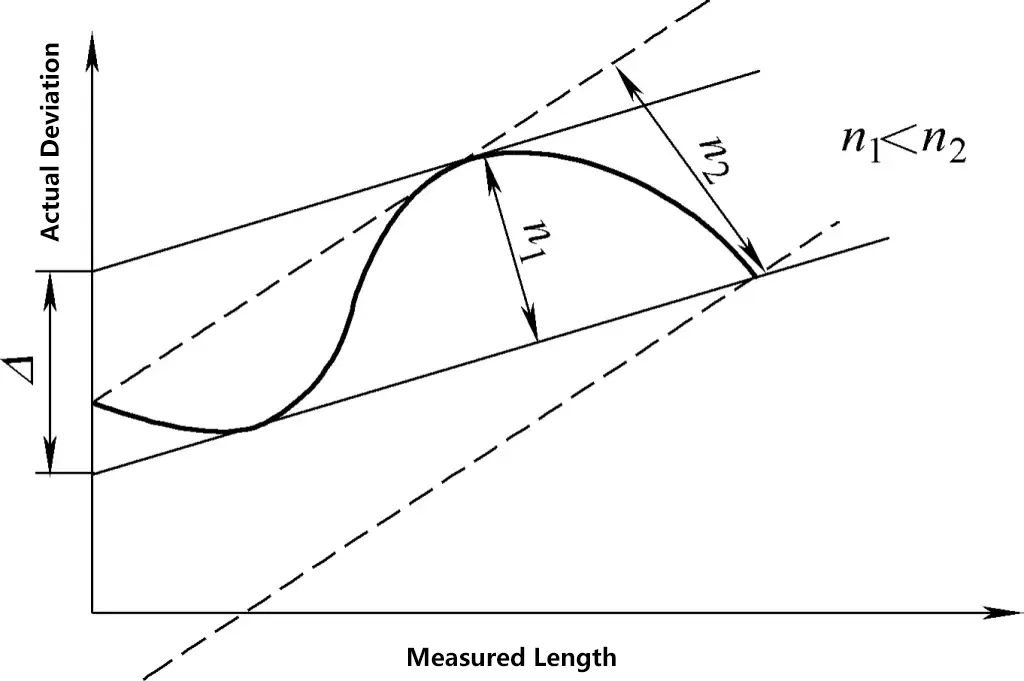
When actually drawing, it is not necessary to draw a set of parallel lines. Instead, draw tangent lines through points on both sides of the curve, and find the maximum distances n₀ and n₁ between each tangent line and the curve. The tangent line with the smaller of these maximum distances is one of the envelope lines.
4) Measurement length. The measurement length is the ordinate of the guide rail motion curve. It is the adjacent distance that the level or gauge moves when measuring the movement accuracy of the guide rail. This distance should generally be the same as the working length of the level or gauge. However, for precise or rough measurement of the guide rail motion curve, it can be smaller or larger than the working length of the level or gauge, as shown in Figure 10.

5) Measurement of single guide rail error. To obtain the closest approximation to the actual geometric surface condition of the guide rail and facilitate measurement using currently widespread measuring instruments, the following unified regulations are made:
The single guide rail error is defined as the coordinate value of the envelope line of the motion curve of the gauge or matching part on the guide rail along the measured guide rail surface, which is called the straightness error of the guide rail. Since the above curve is a spatial curve, for convenience of measurement, the curve is projected onto two orthogonal geometric planes, horizontal and vertical (see Figure 11). The errors are the straightness of the guide rail in the horizontal plane and the straightness of the guide rail in the vertical plane, respectively.
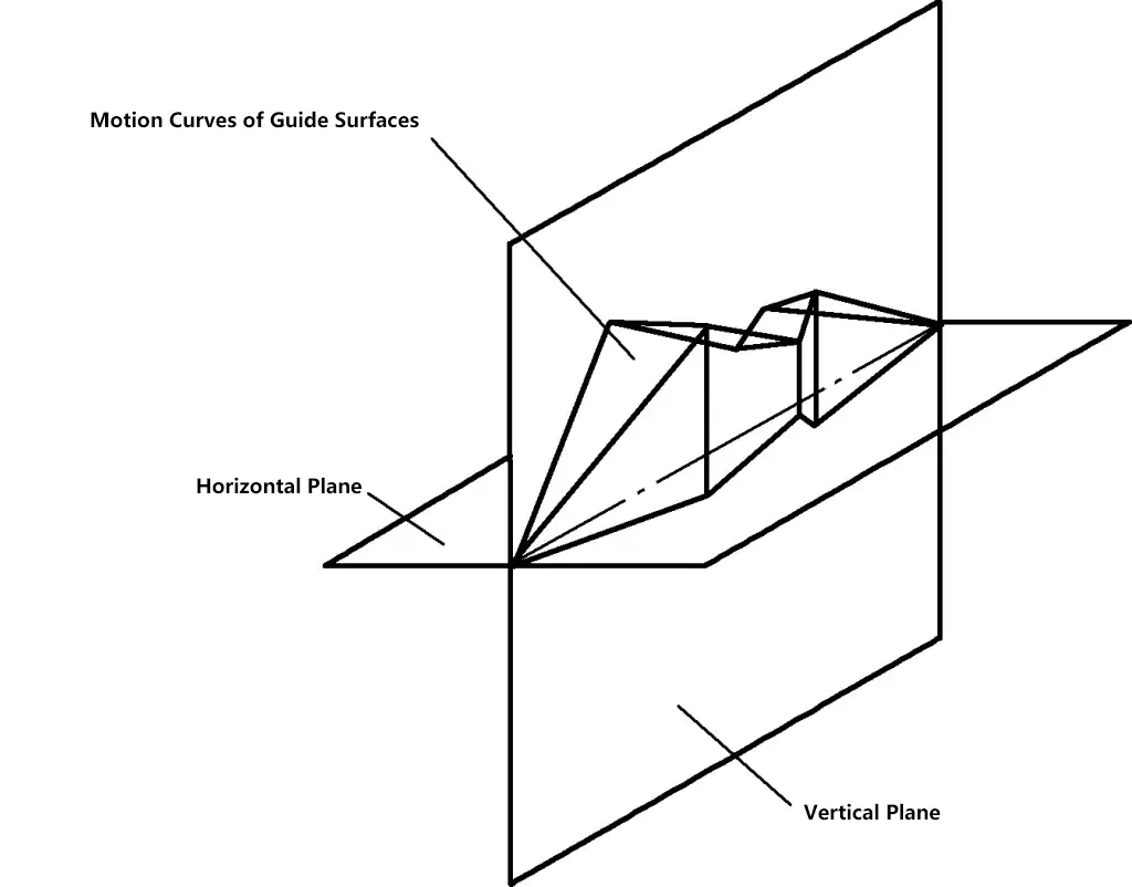
6) Measurement of combined guide rail error. When a machine tool guide rail is composed of two or more single guide rails, in addition to measuring the single guide rail error values, the parallelism (twist) error value of the motion curves of the two guide rails should also be measured.
7) Conversion of deviations. There are two methods to represent the coordinate values of guide rail straightness deviations: linear deviation and angular deviation. Generally, in machine tool accuracy standards, linear deviation is expressed as a tolerance of 0.02mm over a length of 1m, while angular deviation is expressed as 0.02/1000.
Since the readings of various levels and autocollimators are all angular deviation values, the vertical coordinates when drawing guide rail motion curves are all measured in angular deviations. To convert the angular deviation values of the envelope line (vertical) coordinates of the guide rail motion curve to linear deviation values, the working length of the measuring instrument (or gauge) itself must be considered.
For example: When using a level with a reading accuracy of 0.02mm/m and a working length of 250mm to draw the motion curve of the guide rail at certain intervals (assuming the angular deviation value of the vertical coordinate is 0.02mm/1000m per grid), the angular deviation value converted to linear deviation value is 250mm × 0.02/1000 = 0.005mm per grid.
When using an autocollimator with a reading accuracy of 0.005mm/1000m and a working length of 200mm to draw the motion curve of the guide rail at certain intervals, the angular deviation value converted to linear deviation value is 200mm × 0.005/1000 = 0.001mm per grid. Therefore, it can be seen that the conversion of guide rail error values is only related to the length of the measuring instrument and not to the measurement length.
3. Methods for expressing guide rail straightness
In grinding machine accuracy standards, there are several methods for specifying guide rail straightness tolerance.
1) Angular deviation per unit length (e.g., 0.02mm tolerance per 1m); linear deviation over the entire length (e.g., 0.04mm tolerance over the entire length). This specification uses a level to measure long guide rails. To find the angular deviation value per unit length, the maximum difference in level readings can be taken from any two specified interval distances, which can be calculated directly without drawing a curve.
For the linear deviation over the entire length, it is necessary to read the angular deviation values of the level at certain measurement length intervals, then draw the motion curve of the guide rail and obtain the angular deviation coordinate value of the straightness through the method of drawing envelope lines, and finally calculate the error value by converting the angular deviation to linear deviation.
2) Angular deviation for both unit length and entire length (e.g., 0.03mm tolerance per 1m, 0.06mm tolerance over the entire length). This specification generally does not require drawing the motion curve of the guide rail; the maximum difference in level readings over the specified measurement length can be directly taken as the error value.
If there are requirements for convex or concave points on the guide rail, the motion curve of the guide rail should be drawn to verify (some manufacturers do not draw the motion curve of the guide rail but specify the convex or concave point as a boundary, and consider it qualified when the values read on both sides of the boundary are all of the same positive or negative sign).
3) Linear deviation for both unit length and entire length (e.g., 0.02mm tolerance per 1m, 0.04mm tolerance over the entire length).
This specification always requires drawing the motion curve of the guide rail. For the entire length, the angular deviation coordinate value of the straightness is obtained by drawing envelope lines and then calculating the error value by converting the angular deviation to linear deviation. For unit length, it is generally not necessary to draw envelope lines, but only need to represent the coordinate value between the lines connecting the two ends.
4. Drawing of guide rail motion curves
(1) Specification of measurement length
Since the motion curve of a guide rail is a continuous curve, theoretically, error values should be read at every position where the gauge moves to draw the guide rail motion curve. In practice, it has been verified multiple times that the method of reading at intervals of a certain length to draw the motion curve is feasible. Currently, to enable the use of common levels to draw relatively accurate guide rail motion curves, it is often specified that the interval – measurement length – should be equal to the working length of the gauge.
The working length of the gauge (e.g., if the level is 250mm long, the measurement length should be 250mm) can also be controlled by adding a ruler or using a special gauge. Obviously, the working length of the gauge should be determined based on the length of the guide rail being measured (generally, for bed lengths ≤3m, a gauge length of 250mm is recommended; for bed lengths >3m, a gauge length of 500mm is recommended).
Sometimes, to draw an approximate or rough guide rail motion curve, a larger measurement length can be specified. However, it should be noted that the guide rail straightness error value obtained from such a drawn guide rail motion curve is generally smaller than the error value measured according to the standard length. Therefore, the above measurement value should be multiplied by a conversion factor (greater than 1) to approximately determine the guide rail straightness error (this method is usually used for extra-long guide rails).
(2) Basic method for drawing guide rail motion curves
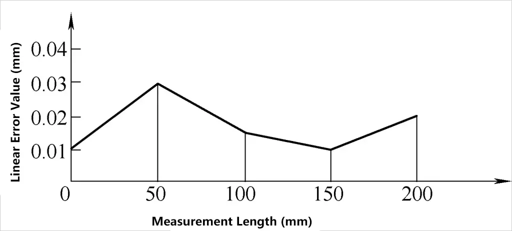
Under general conditions, the motion curve of an object is drawn by directly using the linear coordinate values of the errors of a certain point on the object during its movement, as shown in Figure 12.
| Measurement length/mm | 0 | 50 | 100 | 150 | 200 |
| Linear error value/mm | 0.01 | 0.03 | 0.015 | 0.01 | 0.02 |
Given that most current measurements of guide rail motion curve errors use measuring instruments with angular deviation readings, the drawing of their motion curves is somewhat special, using the reading accumulation method, as shown in table below.
Drawing guide rail motion curve using reading accumulation method
| Measurement length/mm | 0 | 250 | 500 | 750 |
| Angle error value/mm | 0 | +0.02/1000 | 0 | -0.04/1000 |
It should be clear that the first level reading represents the inclination within the measuring plane of that instrument, the second reading reflects the inclination within the measuring plane of the second segment of the instrument, and so on. Therefore, when drawing the guide rail motion curve using angular deviation values, the vertical coordinate only needs to specify the angular deviation value represented by each grid without specific coordinate values (see Figure 14).
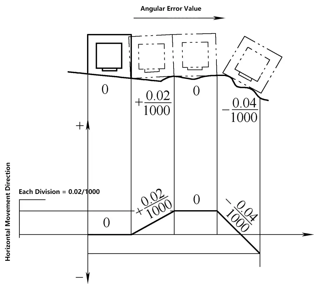
Since the above method of drawing guide rail motion curves actually represents it with continuous small segments of straight lines, the difference between each adjacent pair of straight lines is the angular deviation value read by the instrument (positive and negative signs should be determined according to certain rules).
When measuring the twist error value of the guide rail, although a level is used (with the bubble direction of the level perpendicular to the movement direction of the gauge), the twist curve of the guide rail should still be drawn according to the general coordinate method.
5. Several issues to note
1) Determination of positive and negative signs for angular deviation values when measuring guide rail straightness. When the instrument’s bubble (or cross mark) has an error reading, if the deviation direction of the bubble (or cross mark) is consistent with the movement direction of the instrument during measurement, it is defined as positive; otherwise, it is negative.
When measuring the straightness of the guide rail in the horizontal plane, the determination of positive and negative signs for angular deviation values is based on the reference line of the autocollimator. When the “cross” is to the right of the reference line, it is positive; otherwise, it is negative.
2) The deviation value read at a certain measurement position reflects the angular deviation of the guide rail surface over the working length of that gauge. If the guide rail length is 1m, only four readings can be obtained.
3) The straightness deviation of the guide rail motion curve is not the maximum distance between the parallel lines of the envelope, but the maximum coordinate value. Due to the level’s own horizontal error, the installation level of the machine tool, and the scale used in drawing, there are variations in the linear distance between the two parallel lines, but the coordinate value remains unchanged.
As shown in Figure 15, ABCD is the measured motion curve of the guide rail, where the level readings are +0.02/1000, 0, -0.02/1000. The straightness deviation of this curve is δ₀, where the distance between the envelope parallel lines is consistent with the maximum coordinate value.
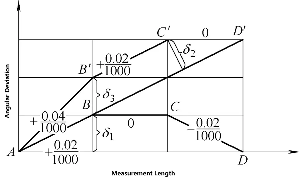
If the bed guide rail is adjusted horizontally to have an inclination angle, making the level readings +0.04/1000, +0.02/1000, 0, then the curve becomes AB’C’D’. The straightness of this curve is δ₀, and the distance between the envelope parallel lines becomes δ₁, which is different from the maximum coordinate value δ₂ (in this case, the maximum coordinate value remains unchanged, δ₃ = δ₄, while the maximum distance value δ₅ has decreased).
From Figure 15, it can be seen that the value of δ₂ decreases as the angle between AD’ and the horizontal coordinate increases.
6. Examples
Based on the drawn guide rail motion curve, conversion calculations are needed to determine whether it meets the specified tolerances for various guide rail straightness parameters.
Here are two examples to illustrate:
1) Use a measuring instrument (working length 250mm) and a spirit level (reading accuracy of 0.02mm/m) to measure the straightness of the M1432 bed longitudinal guide rail in the vertical plane (measuring length 250mm). The measurement results are shown in Table 1.
Table 1 Measurement Results
| Measurement Length/mm | 0 | 250 | 500 | 750 | 1000 | 1250 | 1500 | 1750 | 2000 | 2250 | 2500 | 2750 | 3000 |
| Reading | 0 | +3 | +1 | +1 | +1 | 0 | -1 | -1 | -2 | 0 | +1 | -1 | 0 |
The spirit level readings are shown in Figure 16.
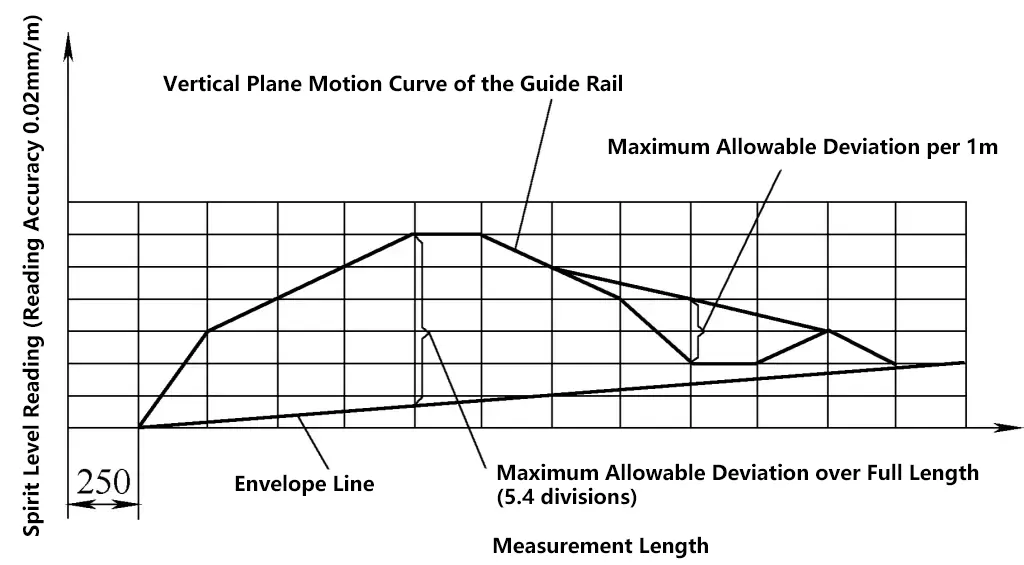
Since the working length of the measuring instrument is 250mm, the reading accuracy of the spirit level (i.e., each division of the spirit level) should be converted to a linear value of 0.005mm. After drawing the motion curve and envelope line (see Figure 16), the maximum error value of the straightness of this guide rail in the vertical plane can be obtained, which is 0.01mm per 1m; the full length is 0.027mm (5.4 × 0.005mm = 0.027mm).
2) Use a measuring instrument (working length 200mm) and an autocollimator (reading accuracy of 0.005mm/m) to measure the straightness of the MG1432 longitudinal guide rail in the horizontal plane (measuring length 200mm). The results are shown in Figure 17.
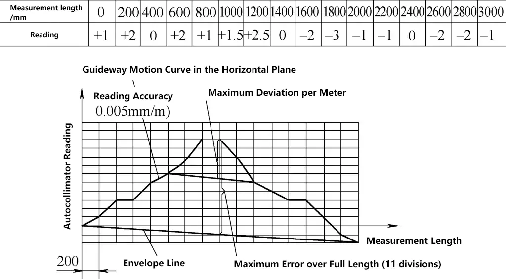
Since the working length of the measuring instrument is 200mm, each division of the autocollimator reading coordinate (i.e., each scale value of the autocollimator) should be converted to a linear value of 0.001mm. After drawing the motion curve and envelope line, the maximum error value of the straightness of this guide rail in the horizontal plane can be obtained, which is 0.0045mm per 1m, and the full length is 0.011mm (11mm × 0.001 = 0.011mm).

