Classification of Drawing Dies
Drawing dies can be categorized based on flange type into those with a binder and those without. They are also classified by operation sequence into first operation drawing dies and subsequent operation drawing dies. Structurally, they can be divided into direct drawing dies, reverse drawing dies, and thinning drawing dies.
Direct and reverse drawing are commonly used in the production of stainless steel products. However, due to the poor thermal conductivity of stainless steel, thinning drawing, which can lead to heat build-up and rapidly deteriorate drawing conditions, is rarely used and will not be discussed in this book.
Direct drawing dies are further subdivided into top-mounted and bottom-mounted types. A top-mounted die, where the punch is above and the die below, is commonly used. Conversely, a bottom-mounted die is where this arrangement is inverted.
Due to the alignment of the drawing punch with the blanking punch, top-mounted drawing dies are frequently employed in progressive drawing operations.
First Operation Drawing Dies
First operation drawing dies are divided into top-mounted and bottom-mounted types.
(a) Top-Mounted First Operation Drawing Dies
For parts without a flange that do not require a binder, or those that require a binder but with minimal force, top-mounted drawing dies are used to enhance efficiency with convenient lower discharge, as shown in Figure 4-10. In single-operation dies, the top-mounted drawing die relies solely on the elastic elements fitted around the punch to provide pressure.
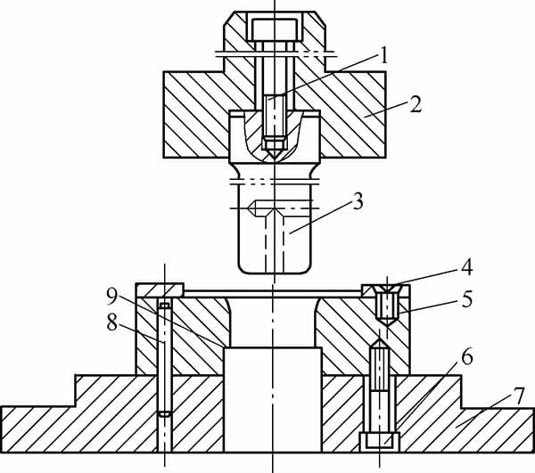
1, 5, 6 – Screws; 2 – Die handle; 3 – Punch; 4 – Locating plate; 7 – Lower die shoe; 8 – Dowel pin; 9 – Die cavity
Therefore, both the blank-holding force and the stroke are quite limited, and these are typically used for parts with a high drawing ratio, without a binder, or with a binder but requiring minimal force.
For non-flanged parts, a through-type discharging method is often used. As the punch rises, a slight rebound in the formed part’s edge causes it to expand and catch on the lower edge of the die, facilitating discharging. Hence, the top-mounted drawing die is highly efficient, as shown in Figure 4-11.
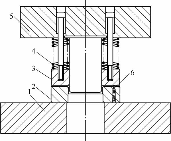
The components are as follows: 1 – Lower die shoe, 2 – Die cavity, 3 – Blank holder, 4 – Spring, 5 – Upper die shoe, 6 – Movable pilot pin.
(b) Bottom-Mounted First Operation Drawing Dies
In practice, bottom-mounted dies are more widely used than top-mounted ones. This is because, when drawing flanged parts on a press, bottom-mounted dies are easier to install, offer more space for elastic elements, provide greater blank-holding force, and allow for easier adjustment of the blank-holder, making operations more convenient.
Most first operation drawing dies installed on hydraulic presses are designed as bottom-mounted, utilizing the lower hydraulic cylinder to adjust the blank-holding force. There are also several conveniences when testing bottom-mounted dies compared to top-mounted ones, as depicted in Figure 4-12.
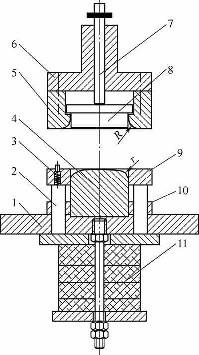
1-Lower die holder 2-Lifter rod 3-Blank locator 4-Punch 5-Die 6-Upper die holder 7-Ejector rod 8-Ejector plate 9-Blank holder 10-Punch retainer plate 11-Stripper mechanism
Subsequent Operation Drawing Dies
(a) Bottom-Mounted Subsequent Operation Drawing Dies
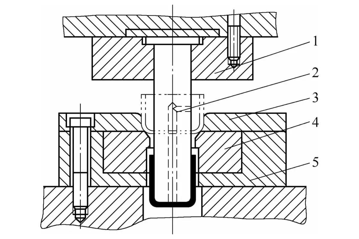
Designing subsequent operation drawing dies as bottom-mounted ensures stable quality in the appearance of the parts. These dies consist of a die, a knockout device, a die set, and a punch, as shown in Figure 4-13.
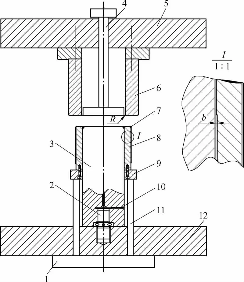
Figure 4-13 illustrates an inverted draw die featuring a standard hydraulic cylinder top plate, universal connecting studs, a punch, a push rod, a hydraulic press slide, a die, a workpiece, a die sleeve, a central bolster plate, vent holes, a lift rod, and a hydraulic press worktable.
(b) Subsequent Operation Drawing Dies without a Binder
Drawing dies for subsequent operations without a binder should have a drawing ratio greater than 0.8 and are commonly used for materials with small thickness and products with small diameters, such as in continuous drawing operations, as shown in Figure 4-14.
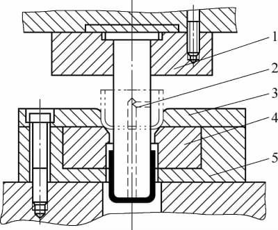
1- Punch Retainer Plate, 2- Punch, 3- Locator Plate, 4- Die, and 5- Die Retainer Plate.
Reverse Drawing Dies
When multiple drawing operations are required for a part, the first operation uses direct drawing, and subsequent operations alternate between reverse and direct drawing to facilitate forming, as shown in Figure 4-15.
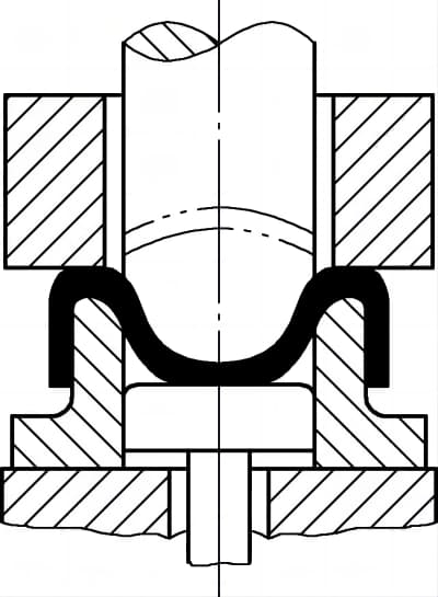
Reverse drawing involves placing the semi-finished product from the first drawing operation onto a hollow die, and the punch enters from the exterior surface for further drawing. The force exerted by the punch on the blank is in the opposite direction to that of the previous drawing operation, allowing the material’s inner and outer surfaces to interchange, which can increase deformation and improve production efficiency.
Reverse drawing has several characteristics:
1) With reverse drawing, the large wrap angle between the blank and the die reduces friction resistance and bending resistance, making wrinkling less likely. When the die wall is thinner than 28t, a binder may not be necessary.
2) Since the force direction and bending are opposite to the previous operation, the work-hardening of the semi-finished product is less than that in direct drawing.
3) The sum of the inner and outer corner radii of the die cannot exceed the die wall thickness. Due to the size limitations of the workpiece, the blank diameter (d) cannot be less than 30t, and the inside corner radius should be greater than 4t.
4) The drawing ratio for reverse drawing should not be too large, as it can reduce the strength of the die. Generally, the drawing ratio can be 10% to 15% less than that of direct drawing.
5) Reverse drawing is challenging for small parts due to the larger required die radii, making it more suitable for medium to large cylindrical parts.
6) The gap between the punch and die in reverse drawing can be 15% to 30% larger than in direct drawing.
7) The die wall thickness must not be less than 10t, and its absolute value should not be less than 6mm.
Reverse drawing offers considerable advantages for forming parts with large unsupported areas. Blanks used in reverse drawing come with flat or spherical tops. During drawing, the contact between the spherical-top blank and the punch is gradual, making it more advantageous for forming hemispherical, conical, or parabolic parts.
Deep Drawing Die Selection
Upon receiving the blueprints, we must broadly categorize the deep-drawn parts. The structural form of the deep drawing die primarily considers the shape of the workpiece, with additional factors as follows:
1) The ratio of material thickness to the maximum blank size.
2) The ratio of blank size to the final formed dimensions.
3) The aspect ratio or the maximum width-to-height ratio.
4) The ratio of the bottom to the open end dimensions.
5) Surface precision.
6) The material’s tensile strength coefficient.
Once all this data is collected, we can determine the appropriate structural form for the deep drawing die.
Die selection for deep drawing should be based on the following conditions:
1) For d0-d1/2 ≤ 7t, use a direct discharge die without a binder ring.
2) For 7 < d0-d1/2 < 14t, use a conical recess die for discharge without a binder ring.
3) For d0-d1/2 ≥ 14t, use a flat recess die with a binder ring.
4) Single operation cylindrical parts should use an inverted deep drawing die. Long cylindrical parts without flanges or with low flatness requirements for the flange may also use an inverted die for multiple deep drawing operations, but intermediate annealing should be arranged if work hardening of the material is severe.
5) For multi-stage deep drawing parts requiring high flange flatness, alternate between positive and negative deep drawing to minimize the effect of lever deflection on flange flatness.
6) For parts with more than three deep drawing stages, consider interspersing 1-2 stages with a conical recess die.
7) For medium-depth conical parts, consider combining positive and negative deep drawing.
8) In the manufacture of stainless steel tableware, for long cylindrical parts where sealing performance is not critical, consider using welded pipes plus bottom attachment as an alternative to deep drawing.
9) Parabolic parts should employ deep drawing followed by hard mold bulging.
10) For streamlined parts prone to wrinkling in the belly, consider deep drawing from the inside out.
11) For parts with insufficient binder area after the second deep drawing stage, consider enlarging the fillet radius of the first deep drawing die and using the inside-out deep drawing method.
12) For parts where the main deformation surface intersects the profile line, use a curved binder ring.
13) If the bottom material has severely thinned after the subsequent deep drawing stages, or there is no material source during forming, and if punching is permissible, add a punching process hole to draw material from the punched area; if punching is not allowed, ensure that this material is in place during the first deep drawing stage.
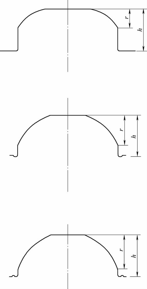
14) For revolving body deep drawn parts, no special measures are needed for surfaces or conical heights less than half the overall height; for greater than half but less than two-thirds of the overall height, use a deep drawing step; for more than two-thirds, use a deep drawing rib, as shown in Figure 4-16.
15) Avoid deep drawing of high conical parts if possible; if allowable, opt for fan-shaped blanking and bending to form conical cylinders followed by welding.
