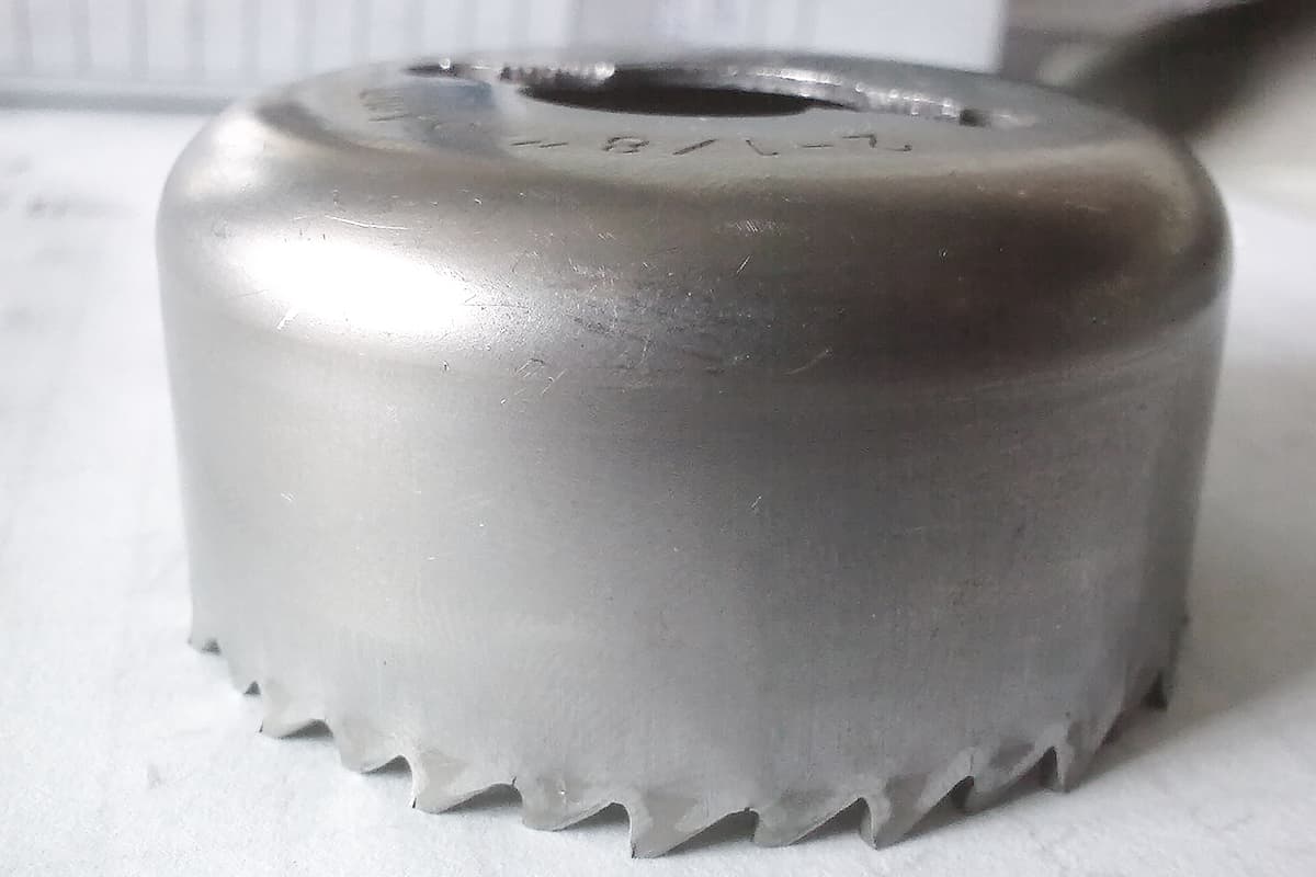
Drawing is a sheet metal forming process in which a flat sheet is pressed into an open hollow part under the pressure of a press and the action of a die.
Generally speaking, drawing processing must use a drawing die to complete the drawing process through the pressure of the press. Figure 1 shows the schematic diagram of the cylindrical drawing process. The blank placed on the surface of the concave die 3 is drawn into the concave die 3 under the blank holder pressure from the blank holder 1 and the drawing force of the punch 2, finally forming a cylindrical drawn part.

1—Blank holder
2—Punch
3—Die
I. Equipment and Tools for Drawing
The drawing forming process can obtain thin-walled parts of various shapes such as cylindrical, stepped, conical, square, spherical, and various irregular shapes.
In production, drawing processing can be conducted on general single-action presses (mostly used for medium and small drawing parts) or on double-action or triple-action presses (mostly used for large and medium-sized complex drawing parts or automotive panels), while the drawing die is the most important tool for completing the drawing process.
Generally, the precision of the drawn part processing is related to the structure and precision of the drawing die and the shape and size of the drawn part itself. The dimensional economic tolerance grade of general drawn parts is best kept below IT11.
1. Common Structures of Drawing Dies
The ever-changing shapes of drawn parts result in a wide variety of drawing die structures. Commonly used drawing dies for sheet metal parts are mostly single-operation dies, which complete only one drawing per press stroke.
Drawing dies can be divided into two types based on the processing sequence of drawn parts: initial drawing dies and subsequent drawing dies. They can also be classified into those with or without a blank holder, depending on whether a blank holder is used.
(1) Drawing Dies Without Blank Holder
Figure 2 shows the structure of the first drawing die for non-flange cylindrical parts without a blank holder. The shallow groove D on the upper surface of the concave die 2 in the figure is used for placing the drawing blank. Its depth has no special requirement, as long as it is convenient for blank placement.

1—Lower template
2—Die
3—Punch
4—Upper template
(2) Drawing Dies With Blank Holder
Figure 3 shows the structure of the die using a blank holder for the initial drawing. The blank holder 4 is installed on the lower die, and the blank holding force is transmitted through the ejector pin 5 installed on the lower die. The source of the blank holding force can be an elastic buffer, a spring, or a cylinder force from the press, etc. The blank material is placed and positioned in the positioning ring of the blank holder 4. The cooperation of the punch 3, die 2, and blank holder 4 draws out the blank.
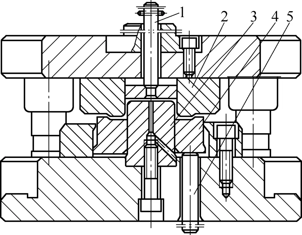
1—Push rod
2—Die
3—Punch
4—Blank holder
5—Ejector pin
The die structure shown in Figure 3 can also be used for the initial drawing and subsequent drawings of drawn parts with flanges. During drawing, the previously drawn flange is positioned in the positioning ring of the blank holder 4.
2. Structural Composition of Drawing Die
As introduced above, the drawing die generally consists of three parts: the punch, the die, and the blank holder (sometimes it can be without a blank holder). In addition, there are positioning devices and discharging devices, among others. The punch and die are the core components that directly produce the drawing action on the material, while the blank holder is mainly used to adjust the pressure on the blank and control the feeding resistance of the blank.
II. Determination of Drawing Process Parameters
To ensure the quality of drawing parts, it is essential to determine the following process parameters when formulating the drawing process and designing related drawing dies.
1. Determination of the Blank Size for Drawing Parts
The correctness of the calculation of the blank material size for drawing parts directly affects the processing quality of stamping parts. Although the calculation formulas for the blank material of drawing parts with different shapes are different, they follow the same basic principle for calculating the diameter of the blank material: “Since the blank thickness changes very little before and after drawing, the volume before and after deformation remains unchanged, which means the blank surface area before drawing is equal to the workpiece surface area after drawing.”
Before calculating the blank material, considering factors such as uneven clearance of the drawing die and anisotropy of the drawing materials, in most cases, the rim or flange edge of the drawn part is not even and needs to be trimmed. Therefore, a certain trimming allowance Δh must be reserved in the height direction when calculating the blank size.
The trimming allowance Δh for different-shaped drawn parts varies. Table 1 shows the trimming allowance for non-flange cylindrical parts.
Table 1 Trimming allowance Δh for non-flange cylindrical parts (unit: mm)
Total part height h | Part relative height h/d | Supplementary diagram | |||
| 0.5~0.8 | 0.8~1.6 | 1.6~2.5 | 2.5~4 | ||
| 10 | 1 | 1.2 | 1.5 | 2 | 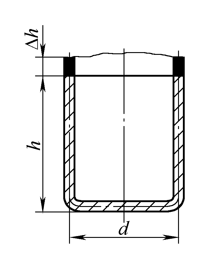 |
| 20 | 1.2 | 1.6 | 2 | 2.5 | |
| 50 | 2 | 2.5 | 3.3 | 4 | |
| 100 | 3 | 3.8 | 5 | 6 | |
| 150 | 4 | 5 | 6.5 | 8 | |
| 200 | 5 | 6.3 | 8 | 10 | |
| 250 | 6 | 7.5 | 9 | 11 | |
| 300 | 7 | 8.5 | 10 | 12 | |
After determining the trimming allowance, the blank diameter D for non-flange cylindrical parts can be calculated using the following formula (the meanings of the parameters in the formula are shown in the supplementary diagram in Table 1):
D=√[d2+4d(h+Δh)]
2. Determination of the Number of Drawing Passes
The degree of deformation of drawn parts with different materials and shapes varies. To draw qualified parts, it is necessary to determine the degree of deformation and thus determine the number of drawing passes. Otherwise, during the drawing process, due to excessive deformation, the tensile stress at dangerous cross-sections may exceed the limit, leading to cracking.
The degree of drawing deformation of drawn parts with different shapes also varies. The number of drawing passes for non-flange cylindrical parts can be determined through two different process calculation methods.
1) Calculate the relative drawing height h/d of the drawn part and the relative thickness t/D×100 of the material. The number of drawing passes can be obtained by directly referring to Table 2.
Table 2 Maximum relative drawing height h/d for non-flange cylindrical parts
| Number of drawing passes | Blank relative thickness t/D×100 | |||||
| 2~1.5 | 1.5~1 | 1~0.6 | 0.6~0.3 | 0.3~0.15 | 0.15~0.08 | |
| 1 | 0.94~0.77 | 0.84~0.65 | 0.7~0.57 | 0.62~0.5 | 0.52~0.45 | 0.46~0.38 |
| 2 | 1.88~1.54 | 1.6~1.32 | 1.36~1.1 | 1.13~0.94 | 0.96~0.83 | 0.9~0.7 |
| 3 | 3.5~2.7 | 2.8~2.2 | 2.3~1.8 | 1.9~1.5 | 1.6~1.3 | 1.3~1.1 |
| 4 | 5.6~4.3 | 4.3~3.5 | 3.6~2.9 | 2.9~2.4 | 2.4~2 | 2~1.5 |
| 5 | 8.9~6.6 | 6.6~5.1 | 5.2~4.1 | 4.1~3.3 | 3.3~2.7 | 2.7~2 |
Note: Large h/d ratio is applicable for the first process with large die corner radius (when t/D×100=2~1.5, rdie=8t to t/D×100=0.15~0.08, rdie=15t), and small ratio is applicable for small die corner radius rdie=(4~8)t.
2) Use formula to directly calculate the number of drawing operations n:
n=1+[lgdn-lg(m1D)]/lgmn
In the formula
- n – number of drawing operations;
- dn – workpiece diameter (mm);
- D – blank diameter (mm);
- m1 – first drawing coefficient, refer to Table 3;
- mn – average drawing coefficient for subsequent drawings, refer to Table 3.
The calculated number of drawing operations is taken as the largest integer value, which is the required number of drawing operations.
Table 3: Drawing Coefficients for Various Metal Materials
| Material | First drawing m1 | Subsequent drawings mn |
| Steel 08 | 0.52~0.54 | 0.68~0.72 |
| Aluminum and aluminum alloy 8A06M, 1035M, 3A21M | 0.52~0.55 | 0.70~0.75 |
| Hard aluminum 2A12M, 2A11M | 0.56~0.58 | 0.75~0.80 |
| Brass H62 | 0.52~0.54 | 0.70~0.72 |
| Brass H68 | 0.50~0.52 | 0.68~0.70 |
| Pure Copper T1, T2, T3 | 0.50~0.55 | 0.72~0.80 |
| Oxygen-free Copper | 0.50~0.55 | 0.75~0.80 |
| Tinplate | 0.58~0.65 | 0.80~0.85 |
| Nichrome Alloy Cr20Ni80 | 0.54~0.59 | 0.78~0.84 |
| Alloy Steel 30CrMnSiA | 0.62~0.70 | 0.80~0.84 |
| Stainless Steel 1Cr18Ni9Ti① | 0.52~0.55 | 0.78~0.81 |
| Stainless Steel 12Cr13 | 0.52~0.56 | 0.75~0.78 |
| Pickled Steel Plate | 0.54~0.58 | 0.75~0.78 |
①The grade 1Cr18Ni9Ti was cancelled in GB/T20878—2007
3. Calculation of Drawing Force
The purpose of calculating drawing force is to select equipment and design molds. For cylindrical parts without flanges, the drawing force F for the first drawing process is calculated as F=πd1tσbk1, and for the second and subsequent processes, the drawing force F is calculated as:
F=πdntσbk2
In the formula
- F – drawing force (N);
- d1, d2, …, dn – diameters of the neutral layers of the cylindrical part for the 1st, 2nd, …, nth process, calculated by the neutral line (d1=d-t, d2=d1-t, …, dn=dn-1-t) (mm);
- t – material thickness (mm);
- σb – strength limit (MPa);
- k1, k2 – coefficients, see Table 4.
Table 4: Coefficients k1, k2 for Cylindrical Part Drawing
| m1 | 0.55 | 0.57 | 0.60 | 0.62 | 0.65 | 0.67 | 0.70 | 0.72 | 0.75 | 0.77 | 0.80 |
| k1 | 1.00 | 0.93 | 0.86 | 0.79 | 0.72 | 0.66 | 0.60 | 0.55 | 0.50 | 0.45 | 0.40 |
| m2 | 0.70 | 0.72 | 0.75 | 0.77 | 0.80 | 0.85 | 0.90 | 0.95 | — | ||
| k2 | 1.00 | 0.95 | 0.90 | 0.85 | 0.80 | 0.70 | 0.60 | 0.50 | — | ||
4. Determination of Drawing Die Clearance
The single-side clearance z of the drawing die is equal to half the difference between the die hole diameter Ddie and the punch diameter Dpunch, which is an important parameter affecting the quality of drawn parts.
Too small a clearance increases friction, making the drawn part easy to fracture, scratch the surface, and reduce die life; too large a clearance makes the drawn part easy to wrinkle and affects part precision. Drawing die clearance is generally considered under the following two situations:
1) Without using a blank-holder, considering the possibility of wrinkling, its single-sided clearance z=(1~1.1)tmax, where tmax is the upper limit of material thickness.
2) When using a blank-holder, the clearance value is selected according to Table 5.
Table 5: Single-side Clearance Value z for Deep Drawing with Blank-holder (Unit: mm)
| Drawing Process | Tolerance Grade of Drawn Part | |
| IT11, IT12 | IT13~IT16 | |
| First Drawing | z=tmax+a | z=tmax+(1.5~2)a |
| Intermediate Drawing | z=tmax+2a | z=tmax+(2.5~3)a |
| Final Drawing | z=t | z=t+2a |
Note: 1. For thicker materials, take the smaller value in parentheses, and for thinner materials (t/D×100=1~0.3), take the larger value in parentheses.
2. In the table, z is the unilateral clearance of the punch and die (mm); tmax is the upper limit of material thickness (mm); t is the nominal thickness of the material (mm); a is the increased value (mm), see Table 6.
Table 6 Increase value a (unit: mm)
| Material thickness | 0.2 | 0.5 | 0.8 | 1 | 1.2 | 1.5 | 1.8 | 2 | 2.5 | 3 | 4 | 5 |
| Increase value a | 0.05 | 0.1 | 0.12 | 0.15 | 0.17 | 0.19 | 0.21 | 0.22 | 0.25 | 0.3 | 0.35 | 0.4 |
When drawing rectangular parts, considering that the material corners will become significantly thicker, the clearance in the corners of the drawing die should be larger by a value of 0.1t compared to the straight edge parts.
When working on a double-action press with a rigid blankholder, it is necessary to specify the minimum clearance for a certain thickness of material, so as not to press the blank dead with no movement, nor allow wrinkles to occur. The increase value a can be determined by the formula: a≈0.15t (t is the material thickness).
In production, for deep-drawn parts with high precision requirements, a negative clearance is often used, meaning the drawing clearance is set to (0.9–0.95)t.
5. Determining the size of the punch and die working sections
The determination of the working section size of the drawing die mainly includes the punch and die corner radii and the sizes and manufacturing tolerances of the punch and die, all of which directly impact the dimensional accuracy and surface quality of the drawn part.
(1) Determining the corner radius of the drawing die
The corner radius of the drawing die has a significant impact on the drawing process. Generally, the die corner radius should be as large as possible. A larger corner radius can reduce the limit drawing ratio and improve the quality of the drawn part.
However, if the die corner radius is too large, it will weaken the action of the blankholder and may cause wrinkling. When selecting the normal drawing ratio, the die corner radius rConcave for the initial draw can also be selected according to tables 7 and 8.
Table 7 Initial drawing die corner radius rConcave with a blankholder (unit: mm)
| Drawing method | Relative blank thickness t/D×100 | ||
| 2~1 | 1~0.3 | 0.3 ~0.1 | |
| Without flange | (6~8)t | (8~10)t | (10~15)t |
| With flange | (10~15)t | (15~20)t | (20~30)t |
| With drawing ribs | (4~6)t | (6~8)t | (8~10)t |
Table 8 Initial drawing die radius rConcave without a blankholder (unit: mm)
| Material | Thickness t | rConcave | |
| First draw | Subsequent draws | ||
| Steel, brass, pure copper, aluminum | 4~6 | (3~4)t | (2~3)t |
| 6~10 | (1.8~2.5)t | (1.5-2.5)t | |
| 10-15 | (1.6-1.8)t | (1.2-1.5)t | |
| 15-20 | (1.3-1.5)t | (1-1.2)t | |
For subsequent drawing processes, the die corner radius rConcave n can be gradually reduced, generally to rConcave n = (0.6–0.8)rConcave n-1, but it should not be less than 2t.
(2) Determining the punch corner radius rConvex
The impact of the punch corner radius rConvex on drawing is not as significant as the die corner radius rConcave, but if rConvex is too small, it will reduce the effective tensile strength of the danger zone of the cylindrical wall transmission, causing significant thinning at the danger zone.
If rConvex is too large, the width of the blank that does not contact the die surface in the initial stage of drawing will increase, making this part of the blank prone to wrinkling. The selection of the punch corner radius rConvex generally follows the following principles:
1) For the first draw, when t/D×100>0.6, take rConvex=rConcave.
2) When t/D×100=0.3–0.6, take rConvex=1.5rConcave.
3) When t/D×100<0.3, take rConvex=2rConcave.
4) For intermediate draws, take rConvex=(dn-1-dn-2t)/2, or take a value equal to or slightly smaller than the die corner radius rConcave, i.e., take rConvex=(0.7–1.0)rConcave. In the final draw, rConvex should be equal to the radius of the part.
(3) Determining the sizes of punch and die
The sizes of the punch and die are determined according to the following principles:
1) For the drawing die in the final process, the punch and die sizes and their tolerances should be determined according to the workpiece requirements.
2) When external dimensions of the workpiece are required, the die size is used as the reference for calculation, i.e.,
Die size DConcave=(D-0.75Δ)+δConcave0
Punch size DConvex=(D-0.75Δ – 2z)0-δConvex
Where
- D – nominal size of the workpiece shape (mm);
- Δ – tolerance of the workpiece (mm);
- z – unilateral clearance of the punch and die (mm);
- δConvex, δConcave – manufacturing tolerances of the punch and die, respectively. If the workpiece tolerance is above IT13, the manufacturing tolerance of the punch and die is between IT6 and IT8. If the workpiece tolerance is below IT14, the manufacturing tolerance of the punch and die is IT10.
3) When internal dimensions of the workpiece are required, the punch size is used as the reference for calculation, i.e.,
Die size dConvex=(d+0.4Δ)0-δConvex
Punch size dConcave=(d+0.4Δ+2z)+δConcave0
Where d is the nominal internal size of the workpiece (mm).
4) For intermediate transition processes of semi-finished products, since strict restrictions are not necessary, the die size just needs to match the transitional blank size. If using the die as the reference, then
Die size Ddie=D+δdie0
Punch size Dpunch=(D-2z)0-δpunch
III. Installation and Adjustment of Deep Drawing Dies
During deep drawing process, firstly, it is necessary to strictly follow the stamping operation procedures to prevent misoperation. Secondly, to ensure a good deep drawing of parts, proper installation and adjustment of the die should be carried out.
The most frequently used deep drawing of sheet metal is done on a single-action press, and its installation and adjustment methods mainly include the following aspects.
1. Installation of Deep Drawing Die
The installation and adjustment of the deep drawing die are similar to the bending die. In addition to common problems such as discharge devices and elastic unloading devices encountered during debugging of blanking and bending dies, there is a specific issue regarding the adjustment of the blank holder force.
If the blank holder force is too large, the drawn parts are prone to cracking, if too small, the parts are prone to wrinkling. Therefore, to some extent, the adjustment of the blank holder ring pressure is crucial to the success of deep drawing processing. The pressure adjustment should be done continuously, making adjustments as needed until appropriate.
If drawing symmetrical or enclosed shaped parts (such as cylindrical parts), during installation and adjustment of the mold, the upper mold can be fastened to the press slide, while the lower mold is placed on the work table without being secured. First, a few spacers equivalent to the workpiece thickness are placed evenly on the cavity wall, then the upper and lower molds are aligned automatically, with even clearance. After the closed position is adjusted, the lower mold is then secured to the work table.
If there is no guiding device for deep drawing die, during installation, standard samples or shims can be used for fitting adjustment, using the method of controlling the drawing clearance to determine the relative positions of the upper and lower molds.
2. Key Points of Deep Drawing Die Adjustment
The adjustment of the deep drawing die should focus on the following aspects:
(1) Adjustment of Feeding Resistance
During the deep drawing process, if the feeding resistance of the die is too large, the product is prone to cracking, while too small, it may wrinkle. Therefore, the key in the adjustment process is to adjust the size of the feeding resistance. The method of adjusting drawing resistance includes:
- Adjusting the pressure of the press slider to work under normal pressure.
- Adjusting the pressing surface of the drawing die blank holder ring to ensure good compatibility with the blank.
- Modifying the fillet radius of the die to make it appropriate.
- Using good lubricants and increasing or decreasing the lubrication frequency.
(2) Adjustment of Blank Holder Force
The method of adjusting blank holder force is: When the punch enters the cavity 10-20mm deep, a trial punch can be started. As the stamping begins, the blank holder ring should be activated, so that the material is subjected to blank holder force. When the blank holder force is adjusted to the point where there are no obvious wrinkles or cracks in the flange area of the deep-drawn parts, the drawing depth can be gradually increased.
The adjustment of the blank holder force should be balanced. Generally, it can be adjusted in two to three stages according to the height requirements of the deep-drawn parts. Each adjustment should ensure that there are no wrinkles or cracks in the workpiece.
When the blank holder force is supplied by the air cushion at the bottom of the press, the force can be controlled by adjusting the pressure of the compressed air. If the force is provided by the elasticity of rubber or springs in the ejector mechanism installed at the bottom of the mold, the amount of compression of the rubber and springs can be adjusted to adjust the blank holder force.
The blank holder force of a double-action press is provided by the outer slider of the press, and the magnitude of which is adjusted by the screw (lead screw) connecting the outer slider. During adjustment, the screw connecting the outer slider should be adjusted evenly to ensure the normal progress of the deep drawing work.
(3) Adjustment of Drawing Depth and Clearance
In the drawing process, inappropriate drawing depth and clearance will lead to unsatisfactory forming of workpieces.
1) When adjusting the drawing depth, the depth can be divided into 2-3 sections for adjustment, starting with a shallower section, and then adjusting deeper, until the required drawing depth is reached.
2) When adjusting the clearance, the upper mold is first fixed on the press slider, and the lower mold is placed on the work table without being secured. A sample is then placed into the die cavity, and the upper and lower molds are aligned and centered. The clearance in all directions is adjusted to be uniform and consistent, after which the molds are at the closed position, the bolts are tightened, and the lower mold is fixed on the work table, and the sample is removed, ready for trial punching.
IV. Operation of Typical Sheet Metal Drawn Parts
In actual production, the variety and structural shapes of drawn parts are diverse. To ensure the processing quality of various drawn parts, it is first necessary to design corresponding molds according to different part structures, develop reasonable processing techniques, and adopt appropriate operations.
1. Deep Drawing Method for Hemispherical Parts
In the deep drawing process of hemispherical parts, the punch only contacts the middle part of the blank at one point. Since the contact point has to bear all the drawing force, the material at the contact point tends to become severely thinner.
Additionally, in the drawing process, most of the material is not pressed by the blank holder ring, so it is easy to wrinkle, and due to the large clearance, the wrinkles produced are not easily removed. Common hemispherical part structures are shown in Figure 4.

Since the drawing coefficient m of hemispherical drawn parts is constant for any diameter, its value is
m=d/D=d/√(2d2)=1/1.414=0.71
Therefore, the drawing coefficient of hemispherical parts cannot be used as a basis for formulating process plans. Instead, the relative thickness t/D of the blank should be used as the main basis for assessing forming difficulty and selecting the drawing method. The principles for formulating its processing plan and mold design are:
1) When the blank’s relative thickness t/D×100% is greater than 3, no blank holder is needed, and a simple mold can be used to draw the hemispherical part. To ensure the surface quality, geometric shape, and dimensional accuracy of the hemispherical part, the die should be designed with a spherical bottom so that a final shaping can be done inside the die at the end of the drawing process. The mold structure is as shown in Figure 5.

2) When the blank’s relative thickness t/D×100 is between 0.5 and 3, a drawing mold with a blank holder is required to prevent wrinkling. At this time, the role of the blank holder is not only to prevent wrinkling in the unsupported middle section but also to induce radial drawing stress and increase expansion due to the frictional resistance caused by the blank holding force.
3) When the blank’s relative thickness t/D×100% is less than 0.5, reverse drawing or a drawing mold with a draw bead is needed. The mold structure is as shown in Figure 6.
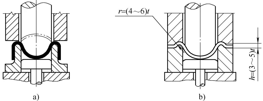
a) Reverse drawing
b) Drawing with draw bead
Furthermore, for the drawing processing of thin materials with small relative thickness of the blank, the following points should also be noted when formulating processing plans or mold designs:
1) For thin, flange-free hemispherical parts, when using a blank holder for drawing, a trimming allowance not less than 10mm in width should be added to the blank, reserved in the form of a flange on the drawn part, otherwise the workpiece is difficult to draw properly.
2) For large thin-walled spherical parts, a combination of direct and reverse drawing methods can be used to eliminate the need for a blank holder (see Figure 7). The gap on each side between the male-female mold and the die is taken as (1.3-1.5)t, and the gap on each side between the male-female mold and punch is (1.2-1.3)t.

3) For thin material hemispherical drawing, hydraulic or rubber forming can also be used, which not only reduces the number of drawings and improves working conditions but also benefits the drawing process.
2. Drawing operation of hemispherical parts
For small and medium-sized hemispherical parts, dedicated drawing molds are usually directly designed to complete them, where the main operation involves the correct installation and adjustment of the molds.
When influenced by production equipment, manufacturing costs, etc., especially for drawing large, thick sheet metal hemispherical parts, point pressing or hot pressing is often used. Point pressing and hot pressing are common methods in sheet metal fabrication; point pressing allows smaller molds to form large workpieces, and hot pressing can achieve the pressing of thicker sheet metal with lower pressure.
(1) Point pressing operation
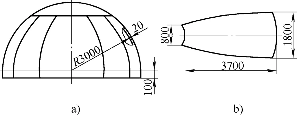
As shown in Figure 8a, the large hemispherical part has an inner diameter of 6000mm, made of 16MnR steel plate with a thickness of 20mm. Due to its large size and thick sheet, it needs to be divided into 11 petals for blanking, with each spherical plate weighing about 800kg. Figure 8b shows the unfolded pattern of one of the petals. When using point pressing, the following precautions should be noted.
1) Principle of point pressing. The operation of point pressing is as shown in Figure 9.
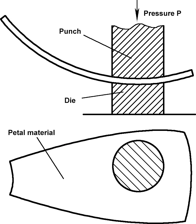
During point pressing, under the external force of the press, the material deforms within the point pressing area of the mold due to the mold’s pressure, creating internal stress within the material that resists deformation, and this stress balances with the external force.
Continuous pressing until the external force equals the material’s yield strength causes the outer layer to undergo plastic deformation, spreading from the outer surface to the center. At this point, pressing stops, and the plastic deformation within the mold is retained, causing permanent deformation. Gradually moving the material for continuous point pressing completes the shaping of the spherical petals.
2) Selection of male and female molds. The molds are generally made from processed cast steel or cast iron materials and can also be assembled from steel plate materials in some cases.
The dimensions of the point pressing mold mainly include the width and radius of the male and female molds. Generally, the width of the male and female molds is determined first, and then their forming radius is set based on the width. Since the width of the male and female molds directly affects the efficiency of point pressing, it is often determined based on factors such as the size of the press’s worktable, the size of the workpiece, and actual construction conditions.
For instance, in this case, the spherical petal pressing uses a 1200t hydraulic press, with the operational surface width inside the columns of the press being 2600mm. Through repeated practice, it has been concluded that the optimal width for the molds is between 800-1000mm. Although increasing the mold diameter can reduce the number of point pressings, it complicates operation and raises mold costs and required operating pressure. Conversely, decreasing the mold diameter results in too many point pressings, increasing material handling labor intensity and reducing efficiency. Therefore, the width of the female mold for this spherical petal is set at ϕ1000mm (see Figure 10).
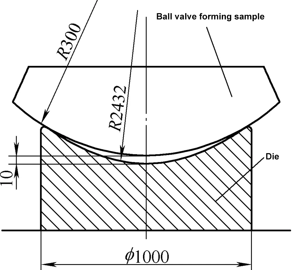
It should be noted that the width of the male mold should be 50-100mm narrower than that of the corresponding female mold to prevent reverse deformation during pressing. In this case, the width of the male mold for the spherical petal is selected at ϕ950mm.
During pressing, the inner layer within the mold’s pressing area is compressed while the outer layer is stretched, leading to elastic deformation alongside plastic deformation. Additionally, due to the tension from the unpressed portion, springback of curvature occurs in the pressing area.
Calculating this springback amount is complex; thus, in production practice, an empirical calculation method is commonly used, which involves leaving a clearance value between the radius of the designed male and female mold surfaces and the required formed surface radius (sheet metal part forming radius), generally taking 10-30mm as appropriate. The pressing is conducted with varied pressure to ensure the designed spherical radius.
This pressing method not only ensures the dimensions of the processed workpiece but also allows the pressing of spherical surfaces with various curvature radii.
As the radius of the workpiece’s spherical surface is large and the plate thickness has little impact, the inner diameter of the sphere R3000mm can be directly used as the template radius for the spherical petal pressing. When the clearance between the concave mold surface radius and the required workpiece forming surface radius (i.e., the template radius for the spherical petal pressing) is set at 10mm, the concave mold surface radius can be calculated to be 2432mm, as shown in Figure 10.
The radius of the convex mold surface is also determined to be 2432mm, but the width of the convex mold is set at 950mm. It should be noted that for other shapes of sheet metal parts, the size of the mold for point pressing can be determined using the same method.
3) Pressing operation method. During pressing, trial pressing should be carried out to select the pressure, then a template check is used to determine the most suitable pressure value. For this spherical petal pressing, a 1200t hydraulic press is used. After trial pressing, the surface pressure of 90-120kg/mm2 is selected, which means using a force of 450-600t for pressing.
To reduce the number of times the sheet is moved and improve efficiency, the pressing order is to gradually move and point-press from the edge, as shown in Figure 11. Based on the material and pressing experience, generally pressing two or three times is enough to form.
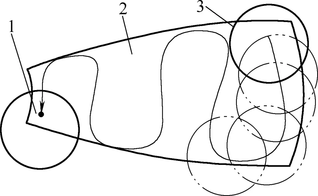
1—The last point of pressing
2—Melon petal material
3—The first point of pressing
The distance moved each time during pressing should not be too large, generally around 100mm. After one round of pressing, use a template to check the longitudinal and transverse directions of the spherical petal. For the same type of material, its rolling fiber direction is related to forming elasticity; forming is better along the rolling fiber direction, while vertical to it results in greater springback, hence, after the first round of pressing, use a template to check that the curvature is smaller along the fiber direction and larger in the vertical fiber direction.
During the second round of pressing, the moving distance should be reduced when moving in the vertical fiber direction, and the pressing points should be densified. Generally, after the second round of pressing, the basic shape is formed. It only requires using a template to check and carry out local point re-pressing. For local trimming, a convex mold with a smaller radius can be used for point pressing, and mastering the appropriate pressure ensures excellent forming quality.
(2) Operation of hot pressing forming
To enhance the deformation degree of materials, reduce material deformation resistance, and ensure the quality of formed parts, hot pressing is often used when the thickness of the sheet metal exceeds 12mm and the thickness of both sides is over 10mm during bending or deep drawing forming.
Hot pressing forming is a method where the deep drawing blank is first heated to a certain temperature and then deep drawing is performed. It should be noted that the operation of hot pressing forming is applicable to point pressing forming or whole deep drawing mold forming, and other types of deep drawing.
1) Temperature for hot pressing forming.
The temperature for metal hot pressing forming should ensure the forming force required for the blank is relatively low while also being above the recrystallization temperature. This is because recrystallization can eliminate internal stresses produced during forming and avoid the occurrence of work hardening. Table 9 shows the hot pressing temperatures for some steel materials. For materials requiring annealing or quenching + tempering treatment, additional heat treatment must be conducted after hot forming.
Table 9 Hot forming temperature for various steels (Unit: ℃)
| Material | Hot forming temperature | |
| Heating | Terminate ≥ | |
| Q235, 15, 20, 25 | 900~1100 | 700 |
| 30, 35, 40, 45, 50 | 950~1050 | 780 |
| Q345, Q345R, Q390, Q420, 14MnMoV, 18MnMoNb, 18MnMoNbR, 15MnVNRE | 950~1050 | 750 |
| Cr5Mo, 12CrMo, 15CrMo | 1000~1100 | 750 |
| 14MnMoNbB | 1000~1100 | 750 |
| 06Cr13, 12Cr13 | 1000~1100 | 850 |
| 12Cr18Ni9, 12Cr1MoV | 950~1100 | 850 |
| Brass H62, H68 | 600~700 | 400 |
| Aluminum and aluminum alloys 1060(L2), 5A02(LF2), 3A21(LF21) | 350~400 | 250 |
Note: The numbers in parentheses are old standard designations.
During hot pressing operation, the heating temperature of the sheet is generally judged by observing the fire color. Table 10 lists the fire color for various temperatures. It should be noted that observing fire color is related to environmental brightness. The colors listed in Table 10 are judged from observing the fire color in a dark place, which will differ when observed in bright daylight.
Table 10 Color of steel when heated to various temperatures (Unit: ℃)
| Color | Temperature |
| Dark brown | 530~580 |
| Red-brown | 580~650 |
| Dark red | 650~730 |
| Dark cherry red | 730~770 |
| Cherry red | 770~800 |
| Bright cherry red | 800~830 |
| Bright red | 830~900 |
| Orange-yellow | 900~1050 |
| Dark yellow | 1050~1150 |
| Bright yellow | 1150~1250 |
| Dazzling white | 1250~1300 |
For example, when observed from a dark place, the sheet is cherry red when heated to 770-800℃. When observed in a very bright environment, the steel will have exceeded 800℃ when it appears cherry red.
2) Clearance of hot pressing dies.
The molds used in hot forming are generally called hot pressing dies. Due to the expansion of the sheet after heating, its thickness increases, and the thickness of the upper part of the workpiece also increases due to hot pressing deformation (especially for hot deep-drawing parts). Therefore, the clearance of the hot pressing mold should be larger than that of the cold pressing mold, and the clearance for hot deep-drawing molds should be larger than that for hot bending molds. Specific values can be referred to in Table 11.
Table 11 Single side clearance value of hot pressing dies (excluding material thickness) (Unit: mm)
| Material thickness | Deep drawing mold | Bending mold | ||
| Minimum clearance | Maximum clearance | Minimum clearance | Maximum clearance | |
| 6~8 | 0.50 | 1.00 | 0.40 | 0.80 |
| 10~12 | 0.80 | 1.25 | 0.60 | 1.00 |
| 14~16 | 1.00 | 1.50 | 0.85 | 1.25 |
| 18~20 | 1.40 | 1.80 | 0.05 | 1.50 |
| 22~24 | 1.75 | 2.20 | 1.30 | 1.75 |
| 25~30 | 2.00 | 2.50 | 1.50 | 2.00 |
3) Calculation of the working part dimensions for convex and concave molds. When designing hot pressing molds, the cold shrinkage phenomenon of the workpiece must be considered, meaning the working part dimensions of the convex and concave molds should be correspondingly enlarged to compensate for the cold shrinkage. Generally, the cold shrinkage can be taken as 0.6%-0.75%.
3. Deep drawing method of parabolic parts
The deformation characteristics of deep drawing for parabolic parts are similar to those of hemispherical parts. Figure 12 shows a schematic structure of parabolic parts. The processing plan and mold design principles are as follows:

(1) Shallow Parabolic Shaped Parts (h/d<0.5)
Its deep drawing characteristics and mold structure are similar to those of hemispherical parts.
(2) Deep Parabolic Shaped Parts (h/d>0.5)
Requires multiple deep draws or reverse drawing. The commonly used methods include:
1) First draw the lower part to an approximate shape by size, then during the re-drawing stage, draw the upper part of the piece, and finally form the entire piece. Figure 13 shows the deep drawing processing sequence of a car headlight cover.

a) Deep Drawing Process 1
b) Deep Drawing Process 2
c) Deep Drawing Process 3
d) Deep Drawing Process 4
2) Use multiple draws to first form an approximated stepped cylindrical shape, then completely form it.
3) Use multiple draws to reduce the drawing diameter, create a circular preform shape, then perform a reverse draw, and finally form it completely.
(3) Parabolic Shaped Parts Made of Thin Material
Use hydraulic or rubber forming.
4. Deep Drawing Operations for Parabolic Shaped Parts
As with hemispherical parts, for parabolic shaped parts of different shapes and sizes and material thicknesses, their deep drawing operations can use methods such as point pressing, hot pressing, and direct integral forming, with operations similar to those for hemispherical parts.
It should be noted that not only hemispherical and parabolic shaped parts, but also deep drawing of other shaped components can adopt the aforementioned forming methods.
V. Common Defects in Deep Drawn Parts and Solutions
Common defects in deep drawn parts include dimension non-compliance, wrinkles, and cracks. The causes can be related to the deep drawing material, mold debugging or mold issues, and operator errors. Solutions must be based on a careful analysis of defect causes and targeted measures taken. Refer to Table 12 for common defects in deep drawn parts and improvement measures.
Table 12 Common Defects in Deep Drawn Parts and Solutions
| Quality Situation | Causes | Solutions | |
| Dimensions not meeting requirements | Deep drawn part height is insufficient | 1) Blank size too small 2) Die and punch clearance too large 3) Punch fillet radius too small | 1) Increase blank size 2) Change punch or die, adjust clearance 3) Increase punch fillet radius |
| Deep drawn part height is too large | 1) Blank size too large 2) Die and punch clearance too small 3) Punch fillet radius too large | 1) Decrease blank size 2) Grind punch or die, adjust clearance 3) Decrease punch fillet radius | |
| Uneven wall thickness, sloped with respect to workpiece bottom | 1) Misalignment of punch and die axes causing uneven clearance 2) Misalignment of die and positioning components 3) Punch axis not perpendicular to die top surface 4) Uneven blank holder force 5) Incorrect die shape | 1) Align punch or die to be concentric 2) Adjust positioning component’s position 3) Adjust punch or die 4) Adjust the blank holder device 5) Correct the die shape | |
| Wrinkle | 1) The blank holder force is too small or uneven 2) The clearance between the punch and die is too large 3) Material thickness is too small, exceeding its permissible lower limit deviation, or the material has low plasticity 4) The die fillet radius is too large 5) A blank holder ring was calculated to be used but was not applied | 1) Adjust the blank holder force 2) Adjust clearance; replace punch or die 3) Replace material 4) Grind the die or modify the blank holding device 5) Use a blank holder ring | |
| Cracking or breaking | 1) Poor material quality (surface roughness, uneven microstructure, surface scratches, abrasions, etc.) 2) Blank holder force is too large or uneven (material becomes thinner, showing ductile fractures) 3) Die fillet is not smooth, with wear or cracks 4) Die fillet radius is too small (material becomes severely thin) 5) Clearance between punch and die is too small (material becomes severely thin) 6) Unreasonable process specifications (such as lubrication, annealing, etc.) 7) Punch fillet radius is too small 8) Blank edge does not meet the requirements, with large burrs 9) Blank size is too large, shape is incorrect 10) Punch and die are not concentric and not parallel 11) The drawing ratio is too small | 1) Replace with suitable material 2) Adjust the blank holder force 3) Grind or replace die 4) Increase the die fillet radius 5) Grind punch or die and adjust clearance 6) Modify process specifications 7) Grind punch 8) Adjust blanking die, remove burrs 9) Modify blank size and shape 10) Adjust punch and die 11) Increase the number of processes and adjust deformation in each process | |
| Surface scratching | 1) Clearance is too small or uneven 2) Die fillet is rough 3) Working surface of punch or material surface is not clean 4) Low hardness of punch and die, with metal sticking to the die 5) Improper lubrication | 1) Grind the clearance between punch and die 2) Grind die fillet 3) Clean the surface 4) Increase hardness of punch and die or replace die 5) Use a reasonable lubricant and lubrication method | |
| The workpiece shape is uneven (such as bottom depression or twisted shape, the bottom of the part is uneven) | 1) No vent holes on the punch 2) The spring-back effect of the material 3) Clearance between punch and die is too large 4) The final deformation degree of rectangular parts is too large 5)The rough blank is uneven, the contact area between the ejector rod and the part is too small, or the buffer spring force is insufficient | 1)Create vent holes or add a shaping process 2)Add a shaping process 3)Adjust the clearance 4)Adjust the degree of deformation in the process or add a shaping process 5)Flatten the blank, improve the ejector device | |

