Drilling and Boring Essentials: Tools and Techniques
In this article, you'll discover the essential tools and techniques used in drilling and boring. From selecting the right drill…
Deep drawing force is an important basis for determining the tonnage of the press required for deep drawn parts. In actual production, some empirical formulas are commonly used to determine the deep drawing force.
Pmax =πdp1tRmK1
Pmax =πdp2tRmK2
Where in the formula
Table 1 Coefficient K 1 for the first deep drawing of cylindrical parts (08 ~15 steel)
| Relative thickness t/D0 ×100 | First deep drawing coefficient m1 | |||||||||
| 0.45 | 0.48 | 0.5 | 0.52 | 0.55 | 0.6 | 0.65 | 0.7 | 0.75 | 0.8 | |
| 5 | 0.95 | 0.85 | 0.75 | 0.65 | 0.6 | 0.5 | 0.43 | 0.35 | 0.28 | 0.2 |
| 2 | 1.1 | 1 | 0.9 | 0.8 | 0.75 | 0.6 | 0.5 | 0.42 | 0.35 | 0.25 |
| 1.2 | 1.1 | 1 | 0.9 | 0.8 | 0.68 | 0.56 | 0.47 | 0.37 | 0.3 | |
| 0.8 | 1.1 | 1 | 0.9 | 0.75 | 0.6 | 0.5 | 0.4 | 0.33 | ||
| 0.5 | 1.1 | 1 | 0.82 | 0.67 | 0.55 | 0.45 | 0.36 | |||
| 0.2 | 1.1 | 0.9 | 0.75 | 0.6 | 0.5 | 0.4 | ||||
| 0.1 | 1.1 | 0.9 | 0.75 | 0.6 | 0.5 | |||||
Note: 1. When the punch radius rp = (4 ~6)t, the coefficient K1 should be increased by 5% according to the table values.
2. For other materials, correct the lookup values according to the change in material plasticity (increase as plasticity decreases).
Table 2 Coefficient K 2 value for the second deep drawing of cylindrical parts (08 ~15 steel)
| Relative thickness t/D0 ×100 | Coefficient m2 for the first deep drawing | |||||||||
| 0.7 | 0.72 | 0.75 | 0.78 | 0.8 | 0.82 | 0.85 | 0.88 | 0.9 | 0.92 | |
| 5 | 0.85 | 0.7 | 0.6 | 0.5 | 0.42 | 0.32 | 0.28 | 0.2 | 0.15 | 0.12 |
| 2 | 1.1 | 0.9 | 0.75 | 0.6 | 0.52 | 0.42 | 0.32 | 0.25 | 0.2 | 0.14 |
| 1.2 | 1.1 | 0.9 | 0.75 | 0.62 | 0.52 | 0.42 | 0.3 | 0.25 | 0.16 | |
| 0.8 | 1 | 0.82 | 0.7 | 0.57 | 0.46 | 0.35 | 0.27 | 0.18 | ||
| 0.5 | 1.1 | 0.9 | 0.76 | 0.63 | 0.5 | 0.4 | 0.3 | 0.2 | ||
| 0.2 | 1 | 0.85 | 0.7 | 0.56 | 0.44 | 0.33 | 0.23 | |||
| 0.1 | 1.1 | 1 | 0.82 | 0.68 | 0.55 | 0.4 | 0.3 | |||
Note:
1. When the punch radius r p = (4~6)t, the K 2 value in the table should be increased by 5%.
2. For the coefficients K 2 of the 3rd, 4th, and 5th deep drawing, the corresponding m n and t/D 0 ×100 values are found from the same table, but the larger or smaller value in the table should be chosen based on whether there is an intermediate annealing process:
Without intermediate annealing, K 2 takes the larger value (closer to the one below);
With intermediate annealing, K 2 takes the smaller value (closer to the one above).
3. For other materials, correct the lookup values according to the change in material plasticity (increase as plasticity decreases).
Pmax =πdptRmKF
Pmax =πdKtRmKF
Where in the formula
Table 3 Coefficient K F values for the first drawing of flanged drawn parts (08 to 15 steel)
| dF/dP | Drawing coefficient d p /D 0 | ||||||||||
| 0.35 | 0.38 | 0.4 | 0.42 | 0.45 | 0.5 | 0.55 | 0.6 | 0.65 | 0.7 | 0.75 | |
| 3 | 1 | 0.9 | 0.83 | 0.75 | 0.68 | 0.56 | 0.45 | 0.37 | 0.3 | 0.23 | 0.18 |
| 2.8 | 1.1 | 1 | 0.9 | 0.83 | 0.75 | 0.62 | 0.5 | 0.42 | 0.34 | 0.26 | 0.2 |
| 2.5 | 1.1 | 1 | 0.9 | 0.82 | 0.7 | 0.56 | 0.46 | 0.37 | 0.3 | 0.22 | |
| 2.2 | 1.1 | 1 | 0.9 | 0.77 | 0. 64 | 0.52 | 0.42 | 0.33 | 0.25 | ||
| 2 | 1.1 | 1 | 0.85 | 0.7 | 0.58 | 0.47 | 0.37 | 0.28 | |||
| 1.8 | 1.1 | 0.95 | 0.8 | 0.65 | 0.53 | 0.43 | 0.33 | ||||
| 1.5 | 1.1 | 0.9 | 0.75 | 0.62 | 0.5 | 0.4 | |||||
| 1.3 | 1 | 0.85 | 0.7 | 0.56 | 0.45 | ||||||
Note: When flanging, the value of K F increases by 10% to 20%.
P max =πd n (t n-1 -t n )R m K 3
Where in the formula
Deep drawing work is also one of the important bases for selecting a press. The pressure load of the press is limited by the strength of the crankshaft or transmission gears, while the power load is limited by the kinetic energy of the flywheel, the power of the motor, or its allowable overload level. Therefore, when selecting a press, both the magnitude of the pressure and the work should be considered comprehensively.
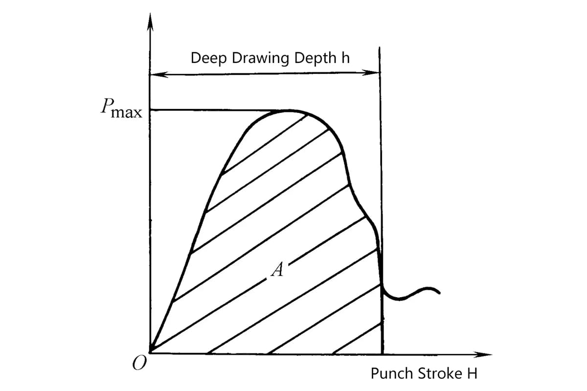
The relationship between deep drawing force and the working stroke of the punch is shown in Figure 1. The deep drawing work should be the area under the curve (shaded part). For convenience of calculation, the following empirical formula is used to calculate the deep drawing work
A=cPmaxh×l0-3
Where in the formula
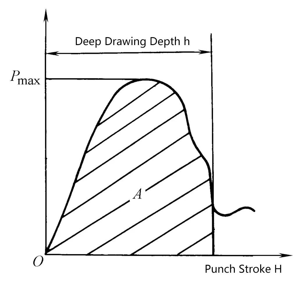
Table 4 Relationship between coefficient c and deep drawing coefficient
| Deep drawing coefficient m | 0.55 | 0.6 | 0.65 | 0.7 | 0.75 | 0.8 |
| Coefficient c | 0.8 | 0.77 | 0.74 | 0.7 | 0.67 | 0.64 |
A=Pmaxh×1.2×l0-3
where
The power of the press motor is calculated by the following formula
P=KA n /(1.36×60×750×η 1 ×η 2 )
where