Punch and Die Clearance: Secrets to Perfect Parts
What if a tiny gap could make or break your next manufacturing project? In the world of punch and die…
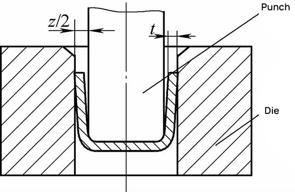
The clearance between the punch and die in deep drawing refers to the lateral dimensional difference between the two, with the bilateral clearance denoted as z, as shown in Figure 1.
When the clearance is small, the roundness of the drawn piece is good, but the drawing force is high, which can easily cause the workpiece to tear and results in severe die wear. If the clearance is too large, the drawing force is reduced, and although the die life is extended, the workpiece takes on a frustoconical shape.
This occurs because during the drawing process, the bottom of the workpiece always clings to the punch, while the mouth adheres to the die. Therefore, for workpieces that require high roundness or those that need to fit together, a detailed and thorough consideration should be given, referencing the material deformation curve.
Once the t/D ratio is determined, whether the blank wrinkles during forming depends on the blank holder force and the die radius.
The clearance in deep drawing should not be negative. In fact, a clearance between the punch and die that is smaller than the material thickness does not have the ability to restrain wrinkling. If the material wrinkles at the flange stage and cannot be smoothed out when passing over the die radius, it will only increase the material flow resistance significantly, leading to workpiece rupture.
For hemispherical workpieces, the clearance between the punch and die can be considered infinitely large, which supports the above statement. From another perspective, ordinary deep drawing dies do not have a feature to control material thickness; and if the clearance between the punch and die is less than the material thickness, the material can either be trapped and stifled in the clearance or, in severe cases, stretch and crack the die.
Therefore, in the design of deep drawing dies, the clearance on each side between the punch and die is generally greater than the material thickness to reduce friction. The formula for calculating the clearance z/2 on each side is:
In the formula,
Table 1: Deep Drawing Die Clearance Coefficient K
| Material Thickness: t/mm | General precision. | Precision deep drawing | Precision deep drawing | |
| Single-stage deep drawing | Multi-stage deep drawing | |||
| <0. 4 | 0. 07 ~ 0. 09 | 0. 08 ~ 0. 10 | 0. 04 ~ 0. 05 | 0 ~ 0. 04 |
| <1. 2 ~ 0. 4 | 0. 08 ~ 0. 10 | 0. 10 ~ 0. 14 | 0. 05 ~ 0. 06 | |
| <3 ~1. 2 | 0. 10 ~ 0. 12 | 0. 14 ~ 0. 16 | 0. 07 ~ 0. 09 | |
| ≥3 | 0. 12 ~ 0. 14 | 0. 16 ~ 0. 20 | 0. 08 ~ 0. 10 | |
The principle of determining the clearance must account for the effects of sheet metal tolerances as well as the phenomenon of thickening at the blank holder.
Experience with stainless steel deep drawing indicates that with a single-operation deep drawing die, the deep drawing coefficient is around 0.52, and the thickening at the blank holder is only 2-3%. This is because the material undergoes compressive tangential deformation, resulting in minimal thickening.
In hardware products, only liquid containers and cosmetic containers have stringent requirements for the roundness of the workpiece. In these cases, precise calculations and strict control of the clearance and manufacturing tolerances between the punch and die for deep drawing are necessary.
For stainless steel kitchenware, the workpiece’s sealing integrity relies on specialized silicone seals, hence the clearance between the punch and die in the cylindrical part drawing molds is typically set at 1.1t or higher. In multi-stage deep drawing, the clearance between the punch and die for all but the last stage is generally set between 1.1t to 1.5t.
1) For all drawing operations except the final stage, the direction of clearance is not specified.
2) Regarding the final stage: when the outer dimensions of the workpiece must be precise, the die dimensions are the standard, and the punch dimensions are reduced from those of the die to achieve the necessary clearance; conversely, when the inner dimensions of the workpiece must be exact, the punch dimensions are the standard, and the die dimensions are increased from those of the punch to obtain the required clearance.