I. Drilling Processing
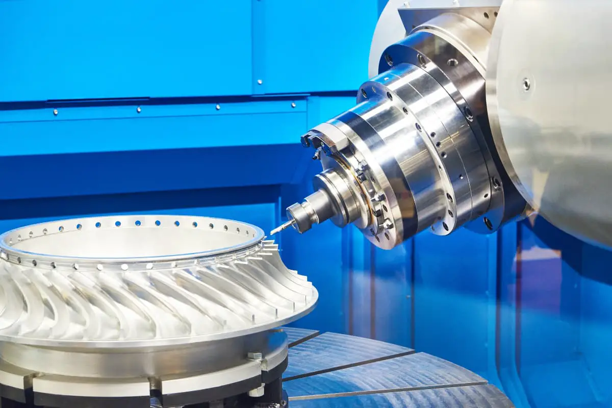
Drilling processing is a method of machining holes in a workpiece using a drill bit. When machining a workpiece on a drill press, generally, the workpiece is fixed in place, and the tool rotates (main motion) while moving axially (feed motion).
1. Characteristics and Applications of Drilling
(1) Process Characteristics
- The drill bit cuts in a semi-closed state, with a large amount of metal removal, making chip removal difficult.
- Friction is severe, generating a lot of heat, making heat dissipation difficult, and cutting temperature high.
- It is not easy to grind the drill bit into symmetrical cutting edges, and the diameter of the hole processed often expands.
- Extrusion is severe, cutting force is large, easily causing cold work hardening of the hole wall.
- The drill bit is thin and has a long overhang, poor rigidity, and is prone to deviation during machining.
- The precision of drilling is low, with a tolerance grade of IT13~IT12, and a surface roughness value of Ra12.5~6.3μm.
(2) Process Range
The process range of drilling is wide. Using different tools on the drill press, it is possible to complete drilling center holes, drilling, reaming, reaming, threading, boring, and facing, as shown in Figure 1. The precision of drilling on the drill press is low, but it is also possible to process holes with high precision requirements (IT8~IT6, surface roughness value of Ra1.6~0.4μm) through drilling—reaming—reaming, and also to process holes with positional requirements using fixtures.
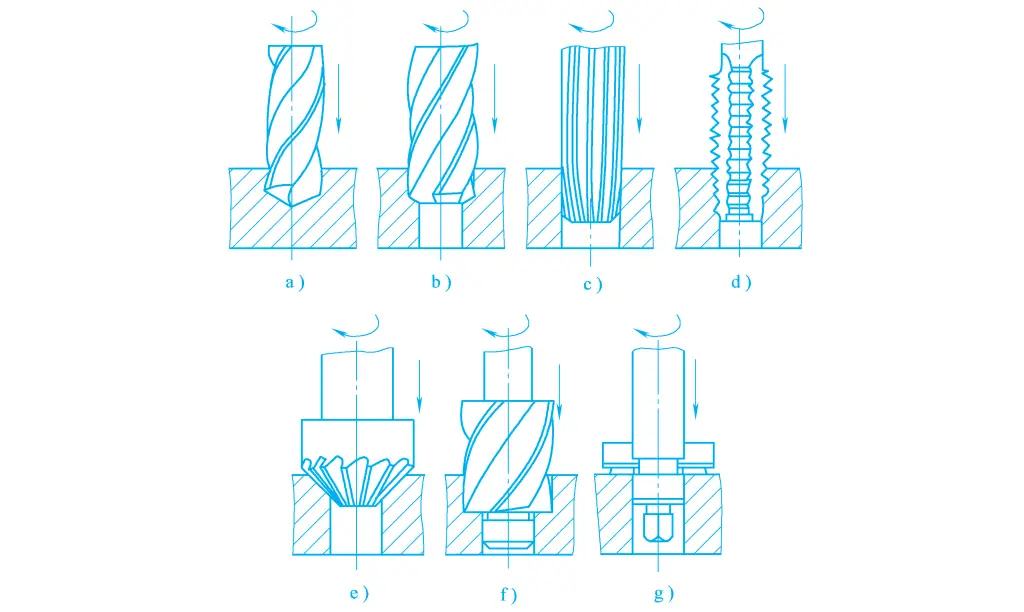
a) Drilling
b) Reaming
c) Reaming
d) Threading
e)、f) Hafnium buried head hole
g) Hafnium plane
2. Drilling machine
The main types of drilling machines include bench drilling machine, vertical drilling machine, radial drilling machine, and specialized drilling machines, etc. Below are introductions to the two most widely used types of drilling machines.
(1) Vertical drilling machine
Vertical drilling machines are divided into three series: cylindrical vertical drilling machines, square column vertical drilling machines, and adjustable multi-axis vertical drilling machines. Figure 2 shows a square column vertical drilling machine, whose spindle is arranged vertically, with its position fixed in the horizontal direction, and the position of the hole to be processed must be found by moving the workpiece.
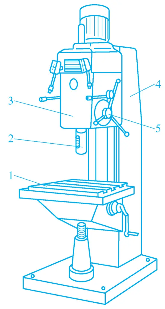
1—Worktable
2—Main spindle
3—Headstock
4—Column
5—Operating mechanism
The spindle box 3 and the worktable 1 are both mounted on the vertical guide rails of the square column 4 and can be adjusted in position to accommodate workpieces of different heights. Once the position is adjusted, their relative positions do not move during processing. In addition to the main rotary motion, the spindle also moves axially for feed motion.
By using the operating mechanism 5 mounted on the spindle box 3, rapid lifting and manual feeding of the spindle can be achieved, as well as the engagement and disengagement of motorized feed. The change in the direction of spindle rotation is achieved by the forward and reverse rotation of the motor. This type of drilling machine has low productivity and is mostly used for single-piece and small-batch production processing of medium and small workpieces.
(2) Radial drilling machine
When drilling holes in large workpieces, it is desirable for the workpiece to remain stationary while the drilling machine spindle can be adjusted to any position. This requires the use of a radial drilling machine, Figure 3a shows the external shape of a radial drilling machine. The base 1 is equipped with a column, which is divided into two layers: the inner column 2 is fixed on the base 1, and the outer column 3 is supported by rolling bearings and can rotate around the inner layer, as shown in Figure 3b. The arm 4 can move up and down along the outer column 3, and the spindle box 5 can move horizontally along the arm guide.
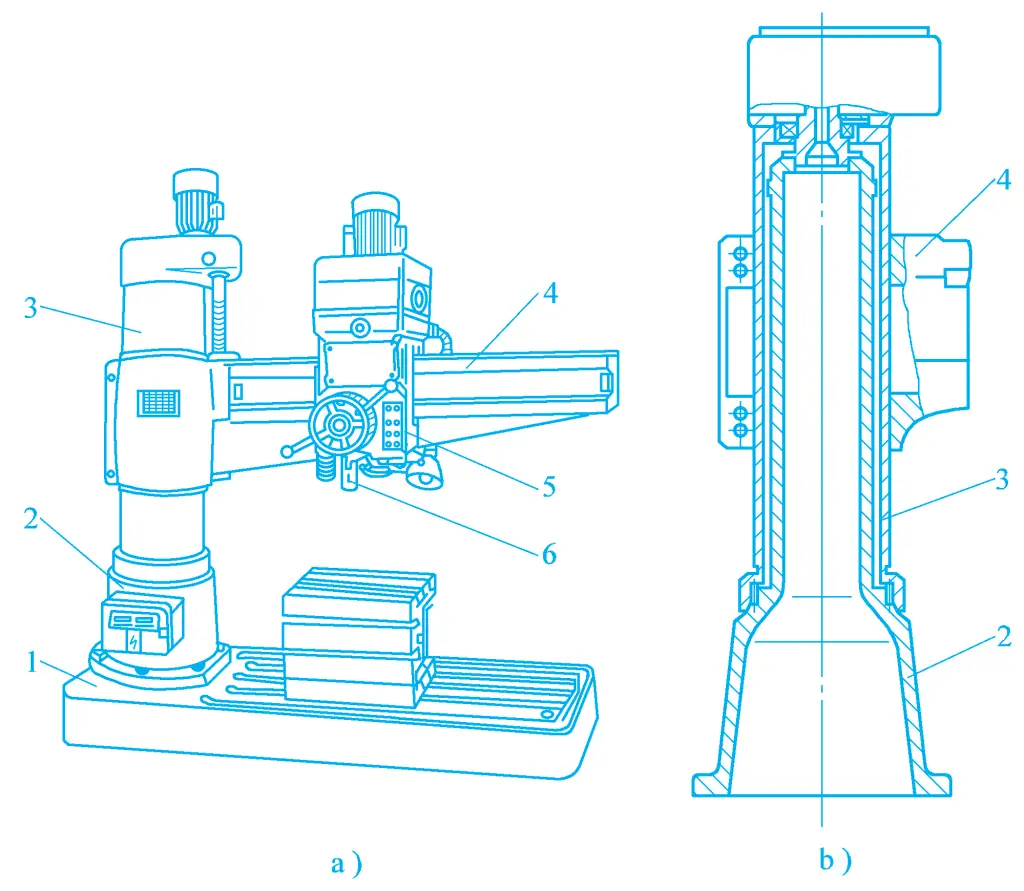
a) External shape
b) Column structure
1—Base
2—Inner column
3—Outer column
4—Arm
5—Spindle box
6—Spindle
Thus, the position of the spindle 6 can be conveniently adjusted. To prevent the spindle from moving horizontally during processing, the radial drilling machine is equipped with clamping mechanisms between the spindle box and the arm, the outer column and the inner column, and the arm and the outer column. The workpiece can be clamped on the worktable, or if the workpiece is large, the worktable can be removed and the workpiece directly mounted on the base. Radial drilling machines are widely used for processing large and medium-sized workpieces.
3. Drilling
The drill bits used in drilling operations are fixed-size cutting tools, which can be divided into flat drills, twist drills, deep hole drills, and center drills according to their structural features and uses, with drilling diameters ranging from 0.1 to 100mm, and a wide range of drilling depths. Drilling operations are widely used for rough machining of holes, and can also be used for the final machining of non-critical holes.
The twist drill is the most widely used drill bit in production, and its application is introduced below.
(1) Composition of the twist drill
The standard twist drill, as shown in Figure 4, consists of a shank, neck, and working part.
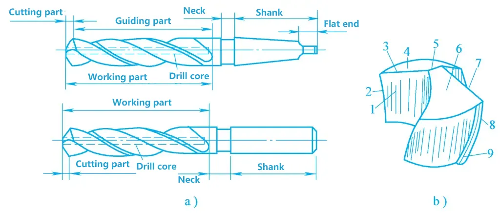
a) Overall structure of the drill bit
b) Cutting part of the drill bit
1—Front
2, 8—Secondary cutting edge (beveled edge)
3, 7—Main cutting edge
4, 6—Main rear
5—Cross edge
9—Secondary rear
1) Shank.
The shank is the holding part of the twist drill, available in straight and taper types, used to transmit torque when drilling. Straight shanks are mainly used for small twist drills with a diameter less than 12mm, generally mounted on the spindle using a drill chuck.
Taper shanks are used for larger diameter twist drills, which can be directly inserted into the spindle’s taper hole or through a taper sleeve into the spindle’s taper hole. The flat tail of the taper shank drill can be used to transmit torque and conveniently remove the drill bit.
2) Neck.
The neck groove is the retraction groove when grinding the drill shank, with the specifications and factory mark of the twist drill engraved at the bottom of the groove.
3) Working part.
The working part of the twist drill consists of the cutting part and the guiding part.
The cutting part undertakes the cutting work, composed of two fronts, main rear, secondary rear, main cutting edge, secondary cutting edge, and a cross edge. The cross edge is the edge formed by the intersection of two main rears, and the secondary rear is the two edge bands of the twist drill, which work opposite the hole wall (processed surface) of the workpiece.
The guiding part acts as a guide when the cutting part cuts into the workpiece, and it is also the spare grinding part of the cutting part. To reduce the friction between the guiding part and the hole wall, its outer diameter is ground with a reverse taper. At the same time, to maintain sufficient strength of the twist drill, a drill core must be present, made into a positive cone towards the direction of the drill shank.
(2) Methods of drilling with a twist drill
There are mainly six drilling methods with a twist drill:
1) Drilling at the marked position.
At the start of drilling, a trial drill should be conducted, which involves drilling a shallow hole (about 1/4 of the hole diameter) with the tip of the drill bit at the center mark of the hole, then checking if the center of the hole is correct, and making timely corrections if deviations are found.
When drilling through holes, reduce the feed rate as the hole is about to break through, to improve drilling quality and prevent small diameter drill bits from breaking. When drilling blind holes, pay attention to controlling the drilling depth, commonly by adjusting the depth stop block on the drill press or making marks, etc.
2) Drilling deep holes.
When the depth of the hole exceeds three times its diameter, frequently retract the drill bit to timely remove chips and cool, otherwise, it may cause chip clogging or excessive wear or even breakage of the drill bit, affecting the quality of the hole.
3) Drilling on hard materials.
The drilling speed should not be too high, manual feed should be uniform, especially when the hole is about to break through, pay attention to appropriately reducing the speed and feed rate.
4) Drilling holes with larger diameters.
When the drilling diameter is large (usually greater than 30mm), it should be drilled in two steps. First drill with a drill bit 0.6~0.8 times the diameter of the hole, then drill to the required diameter. This not only helps to reduce the axial resistance of the drill bit but also helps to improve the drilling quality.
5) Drilling holes in high elasticity plastic materials.
When drilling in materials with good plasticity and high toughness, chip breaking often becomes a prominent problem affecting processing, such as chip clogging the drill bit, affecting the quality of the workpiece; not conducive to the entry of cutting fluid into the cutting area, reducing the life of the drill bit; affecting the safety of operators and the process system, etc.
When such problems occur, they can be improved by changing the geometric angle of the drill bit, reducing the cutting speed, increasing the feed rate, timely retracting the drill bit for chip removal and cooling, etc.
6) Drilling on an inclined surface.
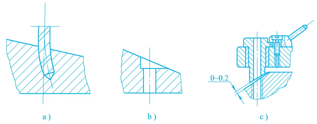
When drilling on a slope, the radial force caused by the slope often causes the drill bit to deviate, resulting in a skewed hole axis (see Figure 5a), or even breaking the drill bit. To prevent the drill bit from deviating, a plane can be reamed on the slope before drilling (see Figure 5b), or a special drill sleeve can be used to guide the drill bit, to increase the rigidity of the drill bit and the precision of the work (see Figure 5c).
When drilling, the drill bit needs to be cooled and lubricated, with steel parts often using emulsion or machine oil, cast iron parts commonly using kerosene, and non-ferrous metals often using emulsion or kerosene.
4. Reaming and Boring
(1) Reaming
Reaming is commonly used to enlarge holes that have been cast, forged, or drilled. Reaming can be used as a pre-machining process before reaming or grinding holes, or as the final machining process for holes with lower precision requirements, commonly used for holes with diameters in the range of 10~100mm. The machining allowance for reaming is 0.5~4mm.
Common reaming tools include twist drills and reamers. Twist drills are generally used for reaming workpieces, and reamers are used for semi-finishing of holes with larger production volumes.
The structure of a reamer is shown in Figure 6. The reamer is similar to the twist drill, but the main difference is that the main cutting edge often has 3 or 4 blades, hence better guidance; the main cutting edge does not go through the center, without a cross blade, which can avoid the adverse effects of the cross blade on cutting; the spiral groove is shallower, and the drill core diameter is larger, so the tool body strength is higher, and the rigidity is better, allowing for an increase in cutting volume during reaming.
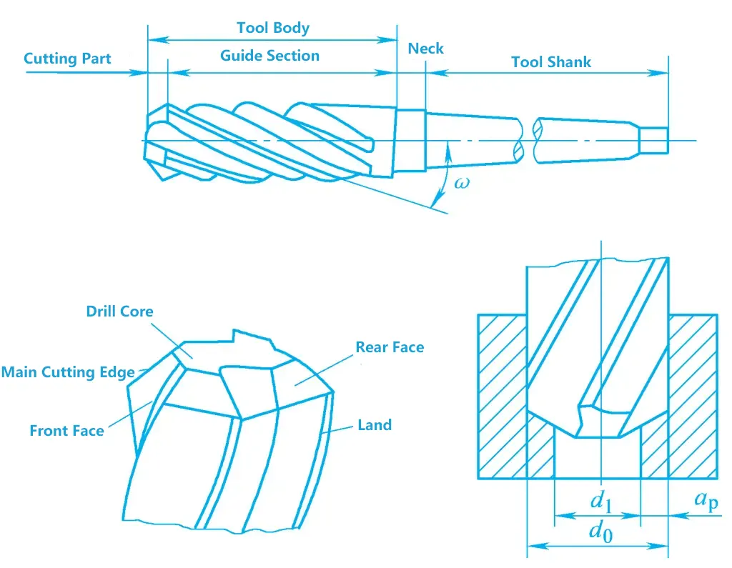
Due to the above characteristics of the reamer, the machining quality of reaming is better than drilling, and the productivity is higher. Reaming has a certain corrective effect on the axis deviation of cast holes, drilled holes, and other pre-machined holes. The dimensional tolerance grade of reaming is generally around IT10, and the surface roughness value can reach Ra6.3~3.2μm.
Except for cast iron and bronze materials, cutting fluid should be used when reaming other materials, with emulsion being the most commonly used.
(2) Boring
Boring refers to the machining of cylindrical countersunk holes, conical countersunk holes, and boss end faces on pre-machined holes. The tools used for boring are collectively referred to as boring drills, generally made of high-speed tool steel.
Boring drills for machining large diameter boss end faces can use hard alloy regrindable inserts or indexable inserts, fixed on the tool body by brazing or mechanical clamping. The guide post of the boring drill ensures the coaxiality of the bored countersunk hole with the original hole.
5. Reaming
Reaming is the process of using a reamer to remove a small layer of metal from the wall of a workpiece hole to improve its dimensional accuracy and reduce surface roughness. It is suitable for semi-finishing and finishing of holes, and can also be used as a pre-machining process before grinding or honing.
Since the cutting allowance during reaming is small, the dimensional tolerance grade after reaming is generally IT9~IT7, and the surface roughness value is Ra3.2~1.6μm, with fine reaming dimensional tolerance grade reaching up to IT6, and surface roughness value of Ra1.6~0.4μm.
Reaming is not suitable for machining hardened steel and materials with too high hardness. Reamers are fixed-size tools, suitable for machining medium and small diameter holes. Before reaming, the workpiece should undergo processes such as drilling and boring (reaming).
(1) Reamers
Depending on the method of use, reamers are divided into hand reamers and machine reamers, as shown in Figure 7. Hand reamers have a straight shank, with a longer working part, providing good guidance, which can prevent the reamer from skewing during manual reaming. Machine reamers often have a taper shank, which can be installed on drilling machines, lathes, and boring machines for reaming.
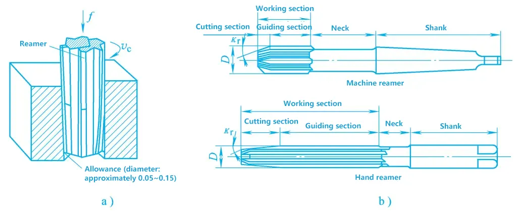
a) Reaming
b) Reamers
The working part of a reamer includes the cutting part and the calibration part. The cutting part is conical, undertaking the main cutting work. The calibration part is used for calibrating the hole diameter, smoothing the hole wall, and guiding, with a very small reverse taper at the rear of the calibration part to reduce friction with the hole wall and prevent the hole diameter from expanding after reaming.
Reamers have 6~12 cutting teeth, with relatively shallow chip flutes and a large drill core diameter, therefore, the rigidity and guidance of reamers are even better than those of reaming drills.
(2) Issues to be aware of when reaming
- The reaming allowance should be moderate. Too large a reaming allowance can cause the reamer diameter to increase due to a large amount of cutting heat, enlarging the hole diameter; chips are easily clogged, cutting fluid cannot easily enter the cutting area, the hole surface is rougher, and the reamer wears out easily; too small an allowance cannot remove the tool marks left in the bottom hole, and the surface roughness does not meet the requirements. The rough reaming allowance is generally 0.15~0.35mm, and the fine reaming allowance is generally 0.05~0.15mm.
- During reaming, a lower cutting speed and smaller feed rate should be used.
- Use cutting fluid reasonably.
- To prevent the reamer axis from deviating from the main spindle axis, causing hole axis skew, hole diameter enlargement, and other phenomena, a floating connection should be used between the reamer and the main spindle. When using a floating connection, reaming cannot correct the deviation of the bottom hole axis, and the positional accuracy of the hole should be ensured by the previous process.
- During the reaming process, the reamer must not be reversed to avoid chips jamming the reamer and scratching the hole wall, causing the reamer to chip.
- The reamer should be sharpened in time after it becomes blunt. Generally, only the back of the cutter is re-ground, and a grinding stone is used to grind the junction of the cutting part and the calibration part of the reamer into a small radius to form a transition blade, in order to improve the life of the reamer and the surface quality of the machining.
II. Boring Machining
Boring machining is a method of processing existing holes with a boring tool.
1. Characteristics and process range of boring
(1) Characteristics of boring
- Boring machining is highly flexible and adaptable. In addition to processing holes and hole systems on a boring machine, it can also process external circles, end faces, etc. The processing size can be large or small, suitable for different types of production and precision requirements.
- Boring machining requires high operational technical skills. To ensure the dimensional accuracy and surface roughness of the workpiece, it depends not only on the equipment used but mainly on the technical level of the workers. At the same time, the adjustment time for machine tools and tools is also longer. During boring, fewer cutting edges participate in the work, so generally, the productivity of boring machining is lower.
- The structure of the boring tool is simple, easy to sharpen, and low in cost.
- Boring can correct the positional error of the hole axis produced in the previous process, ensuring the positional accuracy of the hole.
(2) Process range of boring
The process range of boring machining is wide. It can bore single holes or hole systems, broach, mill planes, bore blind holes, and bore end faces, as shown in Figure 8. Large workpieces with complex shapes such as bases, boxes, and brackets, especially hole systems with positional accuracy requirements, are often processed on boring machines using coordinate devices or boring templates.
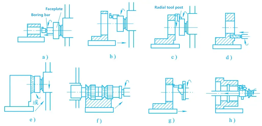
a) Boring small holes
b) Boring large holes
c) Boring end faces
d) Drilling
e) Milling planes
f) Milling combined surfaces
g) Boring threads
h) Boring deep hole threads
When boring, the dimensional tolerance level is IT7~IT6, the hole spacing accuracy can reach 0.015mm, and the surface roughness value is Ra1.6~0.8μm. When equipped with various accessories, special boring bars, and other devices, the boring machine can also process grooves, threads, tapered holes, and spherical surfaces.
2. Boring machines
Boring machines are suitable for processing existing holes on large and medium-sized workpieces, especially suitable for processing hole systems with strict requirements on hole spacing and positional accuracy distributed on the same or different surfaces. The main movement of the working time tool rotates, and the feed movement can be completed by the tool or the workpiece, depending on the type of machine and processing conditions.
Boring machines can be divided into horizontal boring machines, coordinate boring machines, and precision boring machines, etc.
(1) Horizontal boring machine
The horizontal boring machine consists of a bed, a spindle box, a worktable, a rotary table, and front and rear columns, as shown in Figure 9. The spindle box is mounted on the vertical guide rail of the front column and can move up and down along the guide rail. The spindle box contains the spindle components, rotary table, main and feed motion transmission mechanisms, and operating mechanisms. The main motion of the machine is the rotation of the spindle or rotary table.
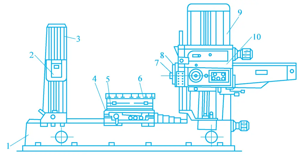
1—Bed
2—Support frame
3—Rear column
4—Lower slide base
5—Upper slide base
6—Workbench
7—Spindle
8—Rotary table
9—Front column
10—Spindle box
According to machining requirements, the boring shaft can make axial feed movement or the radial tool slide on the rotary table can make radial feed movement while rotating with the rotary table. The worktable device consists of a lower slide base, an upper slide base, and a worktable. The worktable can move longitudinally along the bed guide rail with the lower slide base, or it can move laterally along the top guide rail of the lower slide base with the upper slide base.
The worktable can also rotate around the vertical axis along the circular guide rail of the upper slide base, to facilitate the machining of holes distributed on different surfaces. There is a support frame on the vertical guide rail of the rear column to support the longer boring bar, to increase the rigidity of the boring bar. The support frame can move up and down along the guide rail of the rear column to maintain coaxiality with the boring shaft, and the rear column can be adjusted longitudinally according to the length of the boring bar.
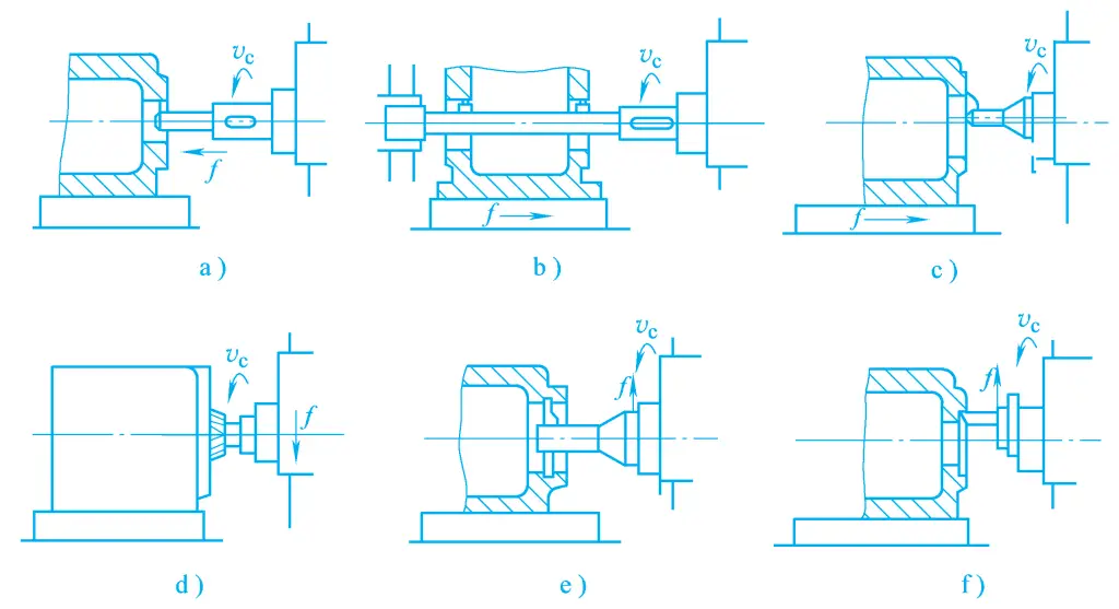
The technological range of horizontal boring machines is very wide, with typical machining methods shown in Figure 10.
(2) Jig boring machine
A jig boring machine is a high-precision boring machine with good rigidity and vibration resistance, and also has a precision coordinate measuring device for moving parts such as the worktable and spindle box, enabling precise positioning of workpieces and tools. Therefore, the dimensional accuracy and geometric accuracy of machining on a jig boring machine are very high.
It is mainly used for the machining of precision holes, hole systems, and mold parts under the condition of single-piece and small-batch production, and can also be used for the precision machining of various types of boxes, cylinder bodies, and machine bodies in batch production. Jig boring machines are divided into single-column, double-column, and horizontal types according to their structure.
1) Single-column jig boring machine
As shown in Figure 11, the spindle box is mounted on the vertical guide rail of the column and can be adjusted up and down to accommodate workpieces of different heights. The coordinate position of the boring hole is determined by the longitudinal movement of the worktable along the bed saddle guide rail and the lateral movement of the bed saddle along the bed guide rail. During boring, the feed movement is completed by the longitudinal or lateral movement of the worktable.
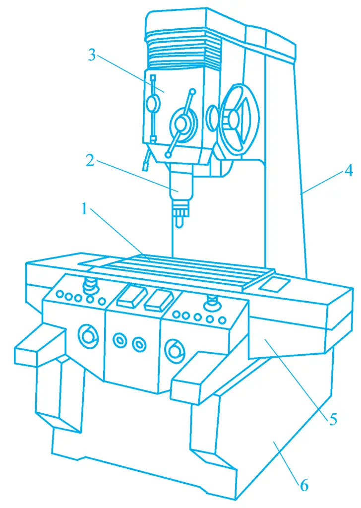
1—Worktable
2—Main spindle
3—Headstock
4—Column
5—Bed saddle
6—Bed
This type of machine tool has three open sides of the worktable, which is convenient for operation, but the spindle box is cantilevered on the column. The larger the size of the worktable, the farther the centerline of the spindle from the column, affecting the rigidity and machining accuracy of the machine tool. Therefore, this type of machine tool is generally medium or small (worktable width less than 630mm).
2) Double-column jig boring machine
As shown in Figure 12, the boring machine consists of two columns, a top beam, and a bed forming a gantry frame, with good rigidity. The spindle box is mounted on a crossbeam that can be adjusted up and down along the column guide rails, and the coordinate position of the boring hole is determined by the movement of the spindle box along the crossbeam guide rails and the movement of the worktable along the bed guide rails. Double-column jig boring machines are generally large or medium-sized machines.
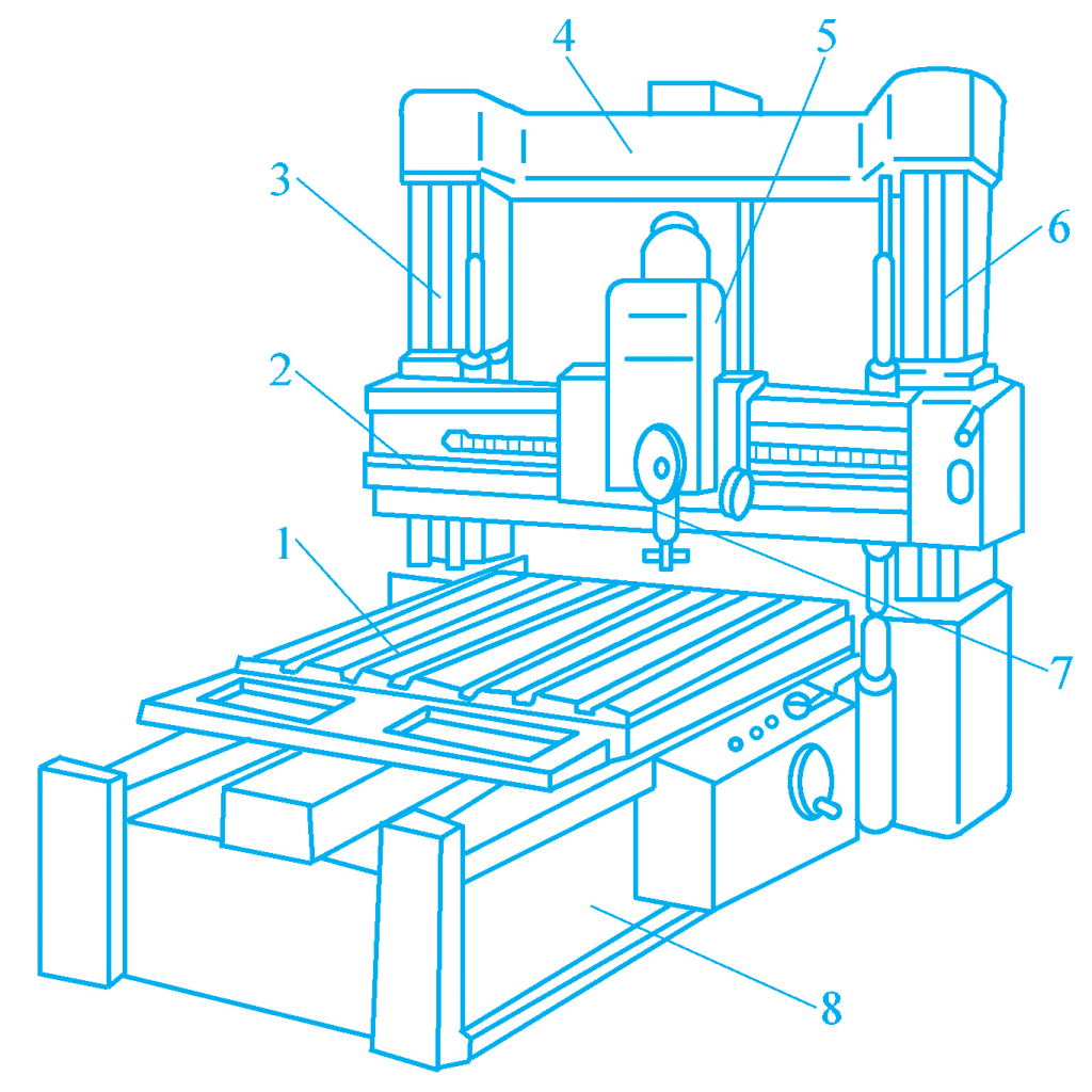
1—Worktable
2—Crossbeam
3, 6—Column
4—Top beam
5—Spindle box
7—Spindle
8—Bed
3) Horizontal jig boring machine
As shown in Figure 13, the structural feature of this type of boring machine is that the spindle is arranged horizontally. The worktable is composed of a lower slide base, an upper slide base, and a rotary worktable that can be precisely indexed. The boring coordinates are determined by the longitudinal movement of the lower slide base along the bed rail and the vertical movement of the spindle box along the column rail.
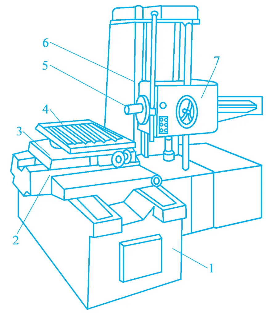
1—Bed
2—Lower Slide Base
3—Upper Slide Base
4—Rotary Worktable
5—Main spindle
6—Column
7—Spindle Box
During hole machining, the feed movement can be completed by the axial movement of the spindle or by the movement of the upper slide base. The horizontal coordinate boring machine has good performance, the height of the workpiece is generally not limited, and it is convenient to clamp. Using the indexing movement of the worktable, multi-directional hole and plane machining can be completed in one clamping of the workpiece.
(3) Precision Boring Machine
The precision boring machine is a high-speed boring machine, named diamond boring machine in the past because diamond was used as the tool material. As shown in Figure 14, now hard alloy is used as the tool material, generally using higher speeds, smaller back cutting amount, and feed amount for cutting, resulting in higher machining accuracy, hence, it is called a precision boring machine. It is mainly used for machining medium and small precision holes in batch or mass production.
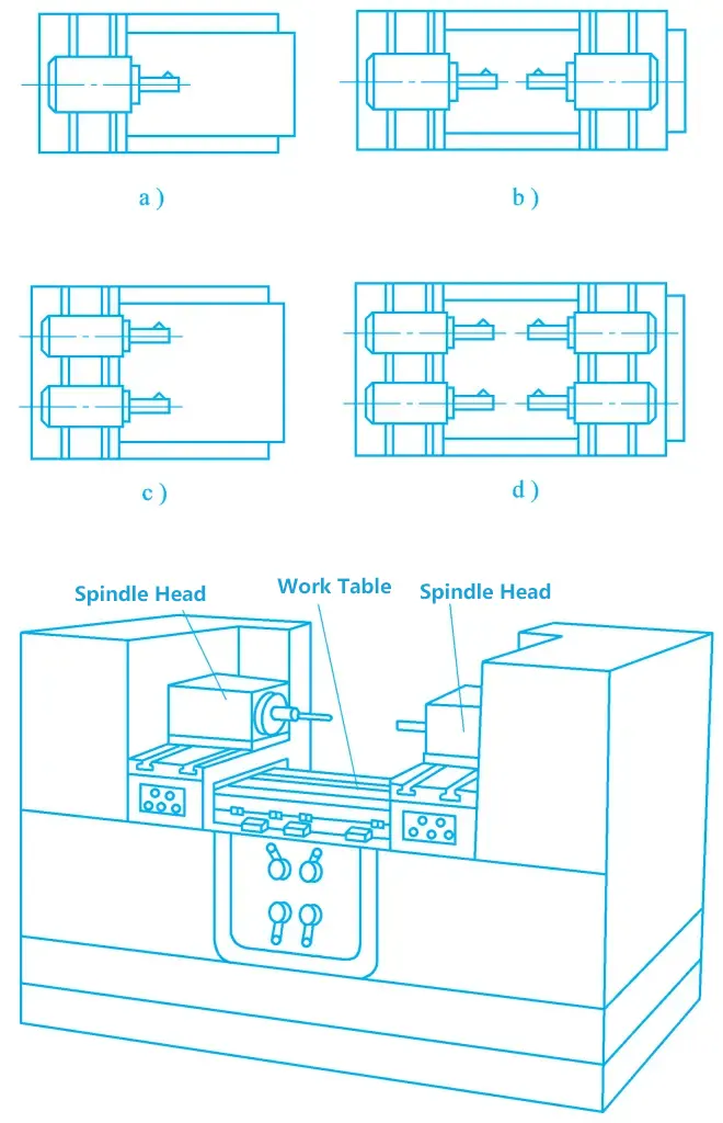
a) Single-sided single-axis
b) Single-sided double-axis
c) Single-sided double-axis
d) Double-sided four-axis
3. Boring Tool
Common boring tools are divided into single-blade, double-blade, and multi-blade, and their structures and characteristics are introduced below.
(1) Single-blade Boring Tool
Most single-blade boring tools are made into the adjustable structure shown in Figure 15, with screw 3 used for adjusting size, and screw 2 for locking. Single-blade boring tools used on lathes often have the boring tool head and the tool rod made as one piece. The cross-sectional size (circular or square) and length of the boring rod depend on the diameter and length of the hole, which can be selected according to relevant tool books or technical standards.
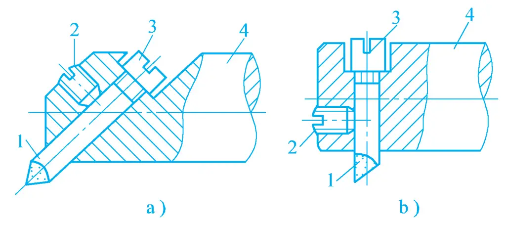
a) Non-through hole boring tool
b) Through-hole boring tool
1—Tool Head
2—Tightening Screw
3—Adjusting Screw
4—Boring Rod
The adjustable structure of the single-blade boring tool only allows the tool head to move in one direction. If the tool head is extended too much during adjustment, it needs to be manually retracted, sometimes requiring multiple repetitions to adjust to the required size, thus the efficiency is low and the adjustment precision is not very high, only suitable for single-piece and small batch production.
(2) Double-blade Boring Tool
A simple double-blade boring tool has a pair of symmetrical cutting edges at both ends of the tool that participate in cutting simultaneously, which can eliminate the influence of radial cutting force on the boring rod. The dimensional accuracy of the workpiece hole is ensured by the size of the boring tool.
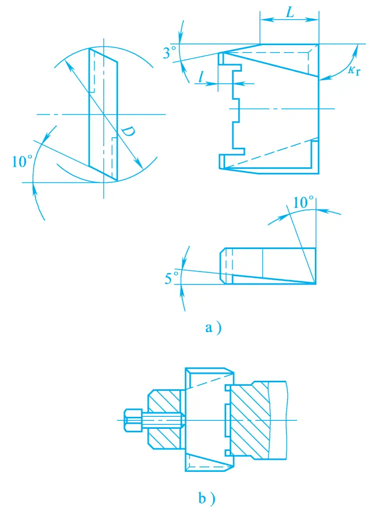
Double-blade boring tools are divided into fixed and floating types. The fixed boring tool block and its installation are shown in Figure 16. The boring tool block can be brazed with hard alloy blades or made entirely of high-speed tool steel. This type of boring tool, due to the limitations of the installation accuracy and structural dimensions of the boring tool block, is only suitable for rough boring and semi-finish boring of holes with diameters larger than 40mm.
a) Boring Bar Block
b) Installation
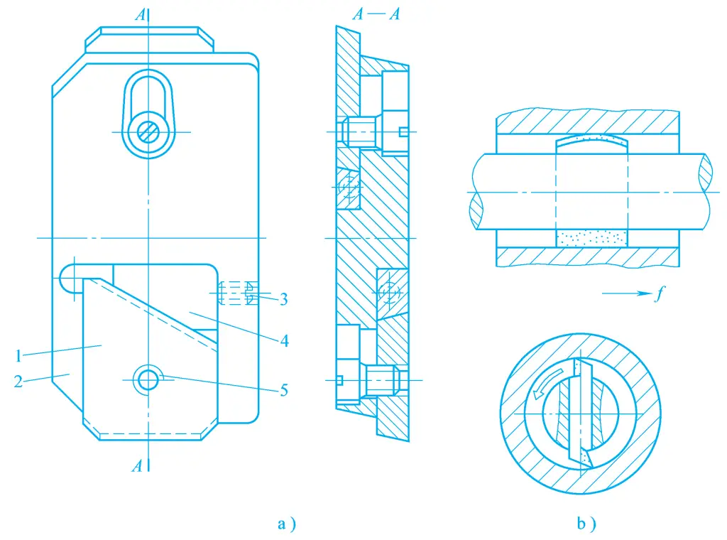
Currently, most double-edged boring bars adopt a floating structure, as shown in Figure 17, which is a commonly used assembly-type floating boring bar. The boring bar block is fitted into the square hole of the boring bar with a clearance fit, without the need for clamping. It is balanced and positioned by the cutting force acting on the cutting edges on both sides during cutting, thus automatically compensating for machining errors caused by installation errors of the boring bar block and radial runout errors of the boring bar.
a) Floating Boring Bar
b) Usage
1—Boring Insert
2—Tool Body
3—Adjusting Screw
4—Bevel Washer
5—Tightening Screw
The hole tolerance grade that can be achieved with this boring bar reaches IT7~IT6, and the surface roughness is Ra1.6~0.4μm. A drawback of the floating boring bar block in the boring bar is that it cannot correct the straightness error and mutual position error of the hole.
(3) Multi-Edge Boring Bar
In mass production, especially when machining non-ferrous metals with small tool wear, multi-edge combined boring bars are often used, that is, arranging multiple boring inserts for radial and axial dimension machining on one boring bar and one cutter head. Although the manufacture and regrinding of this combined boring bar are somewhat troublesome, it still has superiority in terms of overall machining efficiency.
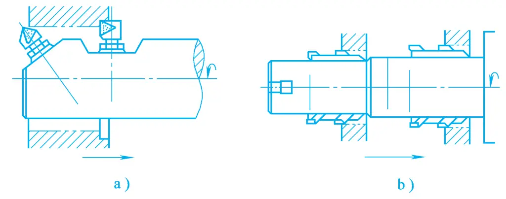
To improve the accuracy and efficiency of boring holes, and to avoid the trouble of regrinding the above-mentioned multi-edge boring bars, a multi-edge combined boring bar can be used during boring, that is, setting two or more cutter heads on one tool body or boring bar, with each cutter head being adjustable independently. A boring bar with two or more cutting edges working simultaneously is known as a multi-edge combined boring bar.
Figure 18a shows a double-edge combined boring bar used for through holes and blind holes, and Figure 18b shows a multi-edge combined boring bar used for rough and fine boring of double holes.
4. Boring Machining Methods
(1) Machining of a Single Surface
1) Boring Small Diameter Holes
The boring bar can be mounted on the spindle to rotate, with the worktable not moving, allowing the spindle to also perform axial feed movement, as shown in Figure 8a. After each feed, the spindle returns to the starting position, then adjust the back cutting amount to continue machining until completion.
2) Boring Shallow Large Holes
Mount the tool holder and boring bar on the flat rotary slide, let the flat rotary plate rotate, driving the boring bar to the required depth, then let the worktable drive the workpiece to perform longitudinal feed movement, as shown in Figure 8b.
3) Machining the End Face of the Hole
Mount the tool on the tool holder of the flat rotary plate, driven by the flat rotary plate to rotate, while the tool holder is fed radially along the flat rotary plate by the tool holder slide, as shown in Figure 8c.
4) Drilling, Reaming, and Reaming Holes
For small holes, drill bits, reamers, and reaming tools can be successively mounted on the spindle, which rotates and performs axial feed movement, to complete the drilling, reaming, and other cutting processes of small holes, as shown in Figure 8d.
5) Boring Threads
Mount the thread boring bar on a specially made tool holder, driven by the boring spindle to rotate, while the worktable moves along the bed by one lead per tool rotation, thus boring out threads.
To control the back cutting amount of each stroke, you can move the special tool holder a certain distance along the direction of its slide at the end of each stroke as needed, as shown in Figure 8g. This method can also be used to machine short external threads. For boring internal threads, another special tool holder can be mounted on the boring bar, which rotates and feeds axially as required, as shown in Figure 8h.
(2) Hole system machining
A hole system refers to two or more holes in space that have certain relative position accuracy requirements. Hole systems are divided into coaxial hole systems, vertical hole systems, and parallel hole systems.
1) Boring coaxial hole systems
The main technical requirement for coaxial hole systems is the coaxiality accuracy of each hole on the coaxial line. The following methods are commonly used in production for machining:
① Guiding method.
When machining hole systems on the casing in single-piece and small-batch production, the deformation of the boring bar due to force can affect the coaxiality accuracy of the holes. In this case, a guiding sleeve can be used for machining coaxial holes.
Use the guiding sleeve on the rear column of the boring machine for support and guidance. Insert the boring bar into the taper hole of the boring spindle, and the other end is supported by the guide sleeve on the rear column, mount the boring tool, and adjust the size. The boring spindle rotates, and the worktable drives the workpiece to make longitudinal feed movement, thus boring two coaxial holes.
If the two holes have different diameters, two boring tools can be mounted at different positions on the boring bar to bore the two holes either successively or simultaneously, as shown in Figure 10b. The disadvantage of this method is that it is time-consuming and troublesome to adjust the position of the guide sleeve on the rear column, and it requires a centering block for alignment, generally suitable for machining large casings.
Use the already machined hole for support and guidance. Once the hole on the front wall of the casing is machined, a guiding sleeve can be installed in the hole to support and guide the boring bar for machining the hole behind, to ensure the coaxiality of the two holes. This method is suitable for machining coaxial holes with relatively close casing walls, as shown in Figure 19.

② Alignment method.
The alignment method involves machining a hole at one end of the casing after a single clamping, then rotating the boring machine’s worktable 180°, and then aligning the hole at the other end of the casing on the coaxial line.
Figure 20a shows aligning the technological base surface parallel to the axis of the hole to be bored on the casing with a dial indicator mounted on the boring bar before boring, making it parallel to the axis of the boring bar, then adjusting the spindle position to machine the hole on wall A of the casing.
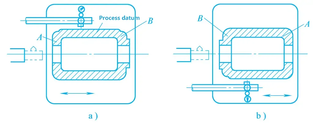
Figure 20b shows that after boring, the worktable is rotated 180°, the technological base surface is realigned to the parallelism requirements of the boring bar axis, then using the technological base surface as a unified measurement benchmark, adjusting the spindle position so that the boring bar axis coincides with the axis of the hole on wall A, thus machining the hole on wall B of the casing.
③ Boring jig method.
In batch production, boring jigs are generally used for machining, with the coaxiality accuracy guaranteed by the boring jig. As shown in Figure 21, the workpiece is clamped on the boring jig, and the boring bar is supported in the guiding holes of the front and rear boring sleeves, guided by the boring sleeves to bore holes in the correct position on the workpiece.
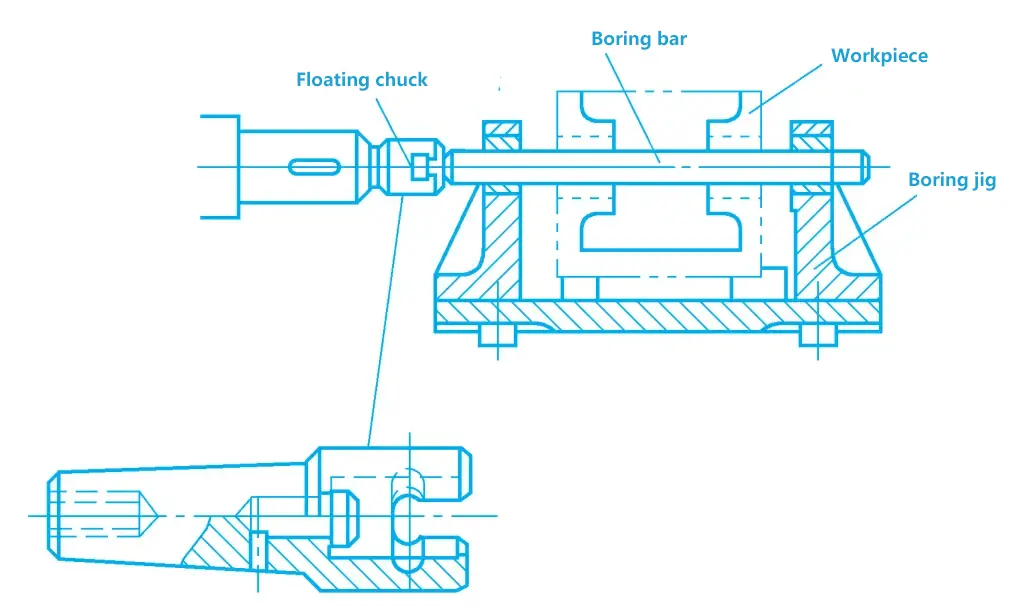
When boring holes with a boring jig, the boring bar is floatingly connected to the machine spindle through a floating chuck, ensuring that the machining accuracy of the hole system is not affected by the accuracy of the machine. In Figure 21, the coaxiality accuracy of the holes mainly depends on the accuracy of the boring jig, thus allowing for machining high-precision hole systems on lower-precision machines.
It also facilitates multi-tool simultaneous cutting, and positioning and clamping are quick, with high productivity. However, the accuracy requirements for the boring jig are high, the manufacturing cycle is long, and the production cost is high, therefore, the boring jig method for machining hole systems is mainly applied in batch production, which can be processed on general-purpose machines, as well as on special-purpose machines or machining centers.
2) Boring parallel hole systems
The main technical requirements for parallel hole systems are the dimensional accuracy and positional accuracy of the distances between the parallel hole axes and between the hole axes and the reference plane. The following methods are commonly used in production:
① Coordinate method.
The coordinate method for boring holes involves converting the hole distance dimensions between the holes in the hole system into two mutually perpendicular coordinate dimensions, then precisely adjusting the relative positions of the machine spindle and the workpiece in the horizontal and vertical directions according to these coordinate dimensions, to ensure the accuracy of the hole distance dimensions through controlling the coordinate displacement dimensions and tolerances of the machine.
② Alignment method.
The alignment method for boring involves using some auxiliary devices to accurately locate the correct position of each hole to be machined on a general-purpose machine. Common alignment methods include:
Line marking alignment method.
Before machining, mark the positions of each hole on the blank according to the drawing requirements, and during machining, align the tool and the workpiece according to the marked lines, also combining with the trial cutting method.
Line marking requires manual operation, is difficult, and the machining accuracy is greatly affected by the skill level of the worker, resulting in low hole distance accuracy and low productivity. Therefore, it is generally suitable for machining hole systems with low hole distance accuracy requirements and small production batches.
Method for aligning the heart axis of a gauge block.
As shown in Figure 22, insert the precision heart axis into the spindle hole of the boring machine and the processed hole, respectively, and then combine gauge blocks of certain sizes to align the position of the spindle.
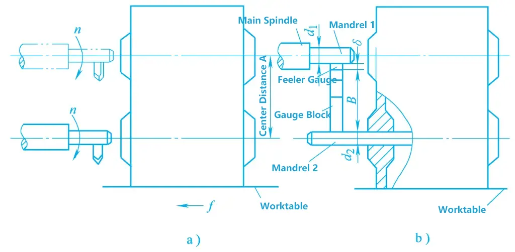
a) Boring parallel holes
b) Aligning with the heart axis gauge block
During alignment, a feeler gauge must be used to measure the gap between the gauge block and the heart axis to prevent deformation from direct contact between the gauge block and the heart axis. This method can achieve higher hole spacing accuracy, but has low productivity and is suitable for single-piece and small-batch production. In the figure, d₁ and d₂ are the diameters of the heart axis, δ is the size of the feeler gauge, A is the center distance of the hole, and B is the size of the gauge block assembly.
③ Boring jig method.
In mass production, boring jig machining is generally used, and its parallelism requirements are guaranteed by the boring jig.
3) Boring vertical hole system
The main technical requirements for the vertical hole system are the perpendicularity requirements between the axes of the holes, and the following two methods are commonly used in production:
① Alignment method.
In single-piece and small-batch production, it is generally machined on a universal machine tool. When boring a vertical hole system, after machining a hole in one direction, the worktable is turned 90° to bore the hole in the perpendicular direction. The perpendicularity accuracy of the hole system is ensured by the 90° alignment device of the boring machine worktable. When the accuracy of the 90° alignment device of the ordinary boring machine worktable is not high, alignment can be done with a heart axis and a dial indicator, that is, insert the heart axis into the machined hole, then rotate the worktable back, and use the dial indicator to align by shaking the worktable.
② Boring jig method.
In batch production, the boring jig method is generally used, and its perpendicularity accuracy is guaranteed by the boring jig.

