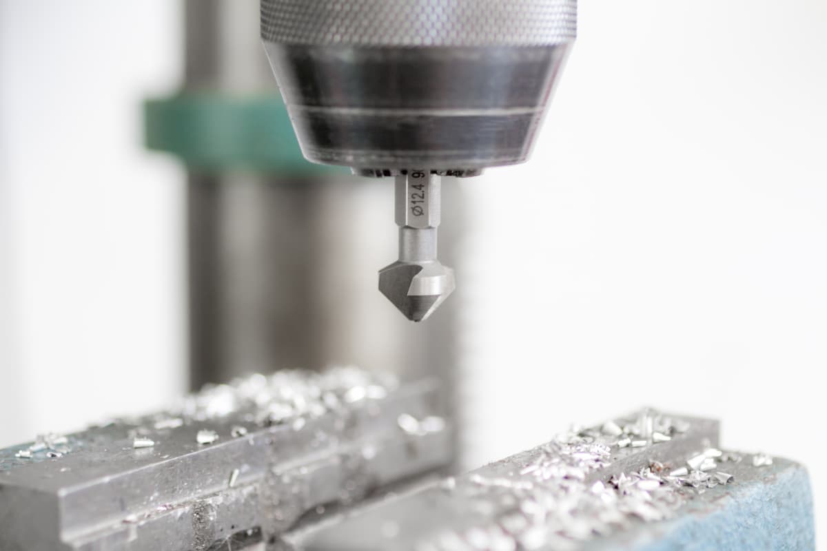
I. Basic Knowledge of Drilling Process
1. Drilling Principles and Applications
The operation of using a drill bit to create a hole in the solid part of a workpiece is called drilling, as shown in Figure 1. During drilling, the workpiece is fixed, and the drill spindle drives the tool to rotate (main motion) while moving the tool downward axially (feed motion). Therefore, the drilling motion is a combination of the main motion and the feed motion.
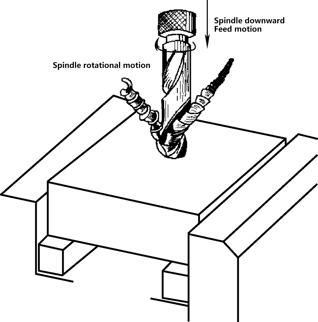
When drilling with a drill bit, due to the influence of the drill bit structure and drilling conditions, the processing accuracy is not high, so drilling is only a rough machining method for holes. The fine machining of holes is usually completed by reaming.
2. Structure of Standard Twist Drill Bits
When drilling holes in metal components, twist drill bits are one of the main cutting tools. Their structure and the names of each part are shown in Figures 2 and 3. The functions of each component of the drill bit are shown in Table 1.


Table 1 Functions of Drill Bit Components
| Drill Bit Part Names | Function | Description | |||
| Shank | Straight shank (cylindrical shank) | Used for holding the drill bit, facilitating clamping, centering, and transmitting torque power | Drill bits with diameter D≤13mm use straight shanks | ||
| Morse taper shank | Drill bits with diameter D>13mm use Morse taper shanks | ||||
| Neck | Used for wheel retraction during drill bit grinding, and for engraving trademarks and specification numbers | The connecting part between the working part and the shank, usually the neck and shank of straight shank drill bits overlap | |||
| Working part | Guiding part (reserve grinding part of the cutting part) | Drill core | Ensures sufficient strength and rigidity of the drill bit | The smaller the drill bit diameter, the larger its core diameter | |
| Flute | Forms the cutting edge | ||||
| Spiral groove | Form cutting edges, remove drilling chips, and deliver cutting fluid | ||||
| Margin | Maintain the straightness of the drilling direction, reduce friction, and polish the hole wall | The diameter gradually decreases from the cutting part to the neck, generally this taper amount is (0.05 0.1mm)/100mm | |||
| Cutting part (six faces and five edges) | Rake face | Chips flow along this surface | The inner surface of the twist drill’s flute is called the rake face | ||
| Flank face | Affects the strength of the cutting part and the friction between it and the cutting surface | The two curved surfaces at the top of the cutting part are called the primary flank faces | |||
| Primary cutting edge | Performs the main cutting action | The intersection line of the rake face and the flank face | |||
| Chisel edge | Initially centers the drill during drilling, while significantly increasing the axial force and consuming energy | The intersection line of the two primary flank faces is called the chisel edge | |||
| Secondary flank face | The attached surface of the margin | The two spiral outer surfaces on the guiding part that face the machined surface (hole wall) are the secondary flank faces | |||
| Secondary cutting edge | Serves to polish the hole wall | The intersection line (spiral line) of the margin and the rake face is the secondary cutting edge, also known as the margin edge | |||
3. Cutting angles of standard twist drills and their impact on cutting performance
(1) Cutting angles of standard twist drills
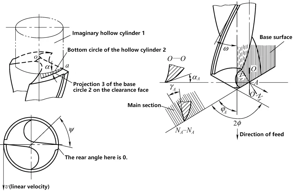
As shown in Figure 4, the cutting angles of standard twist drills mainly include point angle, rake angle, relief angle, and chisel edge angle.
1) Point angle 2ϕ
The point angle of the drill is the angle between the projections of the two primary cutting edges on a plane parallel to them. The standard twist drill has a point angle of 2ϕ = 118° ± 2°. When the point angle 2ϕ ≤ 118°, the two cutting edges form a convex line shape; when 2ϕ > 118°, the two primary cutting edges form a concave line shape.
The smaller the point angle, the smaller the axial force of drilling, which is beneficial for heat dissipation and can improve the durability of the drill bit; however, the cutting torque becomes larger, the chip curling becomes more severe, which is not conducive to chip removal and the addition of cutting fluid.
2) Rake angle (γ)
The rake angle at any point on the main cutting edge is the angle between the tangent of the front face at that point and the projection of the base plane (perpendicular to the cutting line speed direction at that point) on the main section N-N. The rake angle varies at different points along the main cutting edge, with larger angles towards the outer diameter (about 25° to 30°), and negative values within the D/3 range (where D is the drill diameter) near the center of the drill bit. For example, the rake angle γ near the chisel edge is -30°, and on the chisel edge itself, it is -54° to -60°.
3) Back angle α
The back angle refers to the angle between the back face and the cutting plane. As shown in Figure 4, the concept of the drill bit’s back angle can be visually described using the following method. First, make a hollow cylinder 1, and place the bottom circle 2 on the back face of the drill bit. Through observation, it is evident that the bottom circle 2 does not coincide with the back face, and an approximately triangular gap appears. Point a is the vertex of this triangular gap. Thus, the angle α between the hollow bottom circle 2 and its projection 3 on the back face is approximately the back angle value at point a on the main cutting edge.
Similarly, the back angle at any point on the main cutting edge can be visually described, leading to the following conclusion: The back angles at various points on the main cutting edge are not the same. The closer to the drill center, the larger the back angle (the back angle α at the drill center is 20° to 26°), and it is smallest at the outer edge (αo=8° to 14°). The back angle usually refers to the back angle at the outer edge of the drill bit.
The smaller the back angle, the more severe the friction between the back face of the drill bit and the cutting surface of the workpiece during drilling, but the higher the strength of the cutting edge.
4) Secondary back angle
The secondary back angle is the angle between the secondary back face on the secondary cutting edge and the tangent line of the hole wall. The secondary back angle of a standard twist drill is 0.
5) Chisel edge angle ψ
The chisel edge angle is the angle between the chisel edge and the main cutting edge in the projection on the drill bit’s end face. If the chisel edge angle is small, the chisel edge is long, making it difficult to center during drilling, increasing resistance and axial force, and the drill bit is easily broken. Conversely, if the chisel edge angle is large, the chisel edge is short, resulting in less resistance during drilling, but the drill bit’s strength is lower. The chisel edge angle ψ of a standard twist drill is 50° to 55°.
(2) Analysis of cutting performance of standard twist drill bits
- The chisel edge of the drill bit is relatively long, resulting in poor centering effect. It is easy to deviate when starting to drill at the center, and the drill bit is also prone to vibration during the drilling process.
- The rake angle at the chisel edge is negative, resulting in a squeezing and scraping state during cutting, with a large axial resistance, which exacerbates the wear of the drill bit.
- The main cutting edge is relatively long, with wide and severely curled chips, making it easy to clog and difficult to evacuate chips, and cutting fluid is not easy to enter.
- The rake angle values at various points on the main cutting edge are different, resulting in uneven load bearing and different cutting performance at each point, which intensifies the wear on the rake face.
- The outer edge of the main cutting edge is the largest diameter of the drill bit, with the highest cutting line speed, thus being in a high-temperature zone. The rake angle here is larger, the cutting edge is thinner, and the point angle is smaller, making heat dissipation difficult and easily burning the cutting edge.
- The margin is wide and the secondary back angle is 0, resulting in severe wear on the margin.
II. Basic operational skills for drilling
1. Grinding of standard twist drill bits
(1) Grinding requirements for standard twist drill bits
1) Correct grinding angles.
As mentioned earlier, the theoretical point angle is 118°, but it can be adjusted appropriately based on the following specific situations.
① Regarding the grinding of the point angle. A larger point angle results in higher drill bit strength and better chip evacuation, but lower cutting efficiency, suitable for drilling holes in parts with higher strength and hardness. If the point angle is ground smaller, the drill bit is sharper and easier to center, but the cutting edge strength is lower, suitable for drilling soft materials.
Based on experience, the suitable point angle for drilling unhardened structural steel is 116° to 118°; for hardened steel, 118° to 125°; for alloy steel (high manganese steel, chrome-nickel steel, etc.), 135° to 150°; for hard cast iron, 118° to 135°. Specific details can be found in relevant mechanical processing manuals.
② Regarding the grinding of the back angle. To increase the strength of the drill bit’s cutting edge, the back angle can be ground smaller. However, for materials with lower strength, such as aluminum and cast iron, to reduce wear on the main back face of the drill bit and increase chip space, the back angle should be appropriately increased, and sometimes a double back angle can be ground. Specific details can be found in relevant mechanical processing manuals.
2) The two main cutting edges should be of equal length and symmetrical.
3) The back face should be smooth.
(2) Grinding and inspection methods for standard twist drills
1) Two-handed grip method.
As shown in Figure 5a, hold the head of the drill bit with your right hand and the handle with your left hand.

a) Drill bit holding position
b) Drill bit sharpening motion
c) Pressure control when sharpening the drill bit
2) Relative position of drill bit and grinding wheel.
As shown in Figure 5a, the angle between the drill bit axis and the cylinder generatrix of the grinding wheel in the horizontal plane is equal to half of the drill bit point angle 2ϕ, with the main cutting edge being sharpened in a horizontal position.
3) Sharpening action.
As shown in Figures 5b and c, first make contact with the grinding wheel slightly above its horizontal center plane with the main cutting edge. Slowly rotate the drill bit around its axis from bottom to top with your right hand while applying appropriate sharpening pressure, so that the entire clearance face is ground. The left hand cooperates with the right hand to make a slow synchronous downward movement, gradually increasing the sharpening pressure, thus creating the clearance angle. The speed and amplitude of the downward movement vary according to the desired clearance angle.
To ensure a larger clearance angle near the center of the drill bit, an appropriate rightward movement should also be made. The coordination of both hands during sharpening should be smooth and natural. Repeat this action continuously, alternating between the two clearance faces, until the sharpening requirements are met.
4) Drill bit cooling.
The sharpening pressure on the drill bit should not be too high, and it should be frequently dipped in water for cooling to prevent loss of hardness due to overheating and annealing.
5) Grinding wheel selection.
Generally, an aluminum oxide grinding wheel with a grit size of F46 to F80 and medium-soft hardness (K, L) is suitable. The grinding wheel rotation must be stable, and wheels with large runout must be dressed.
6) Grind the chisel edge to improve its centering and cutting performance.
For materials with loose structure, low cutting resistance, and low strength and hardness such as brass, bronze, and aluminum alloys, if a standard drill bit is used for drilling, the large rake angle at the outer edge of the drill bit can easily cause plunging. Therefore, it is necessary to modify the rake angle at the outer edge.
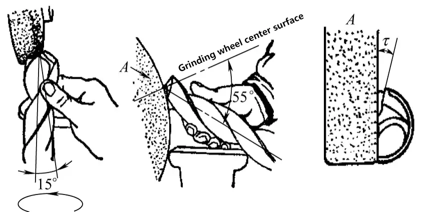
As shown in Figure 6, grinding the chisel edge can reduce the negative rake angle at the drill center, improving cutting conditions at the center and making cutting smoother. After grinding, the length of the chisel edge should be 1/5 to 1/3 of its original length. This forms an inner edge with an inclination angle τ of 20° to 30° and γ of 0 to -15°.
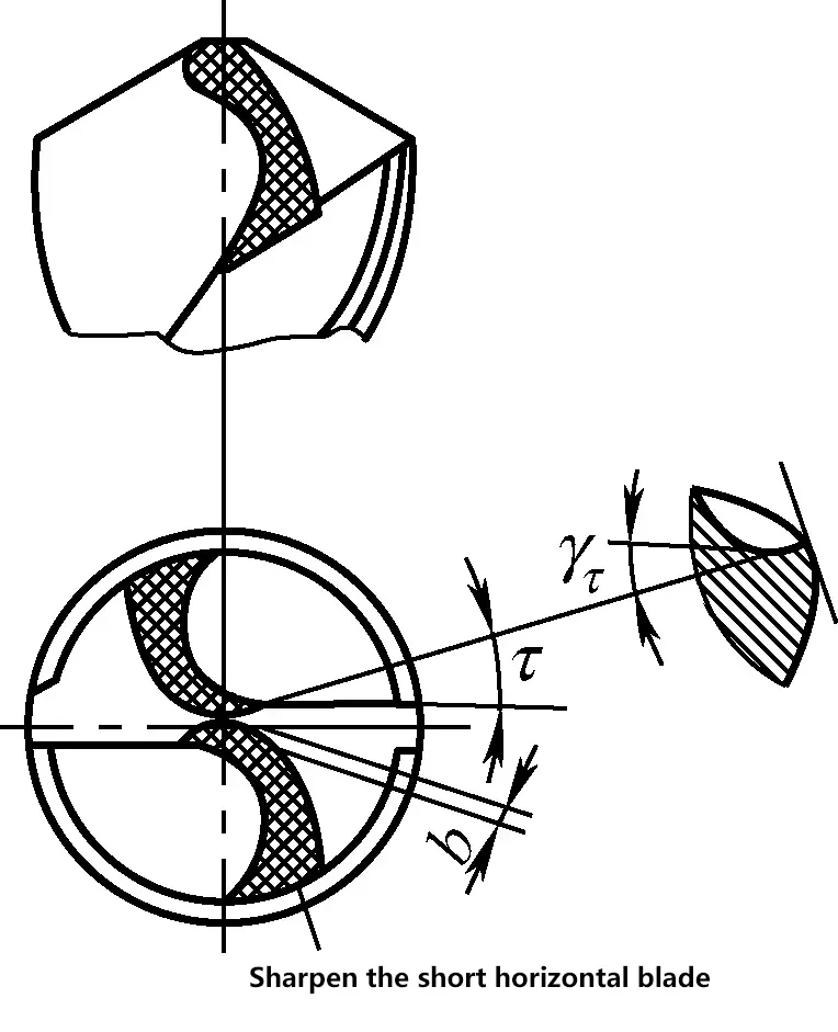
As shown in Figure 7, when grinding, the drill bit axis should be in the horizontal plane and inclined to the left at about a 15° angle with the side of the grinding wheel, and in the vertical plane, it should form a downward angle of about 55° with the radial direction of the grinding wheel at the grinding point.
7) Sharpening inspection.
As shown in Figure 8, the geometric angles of the drill bit and the symmetry of the two main cutting edges need to be inspected using a checking template. However, visual inspection is still the most commonly used method during the sharpening process.
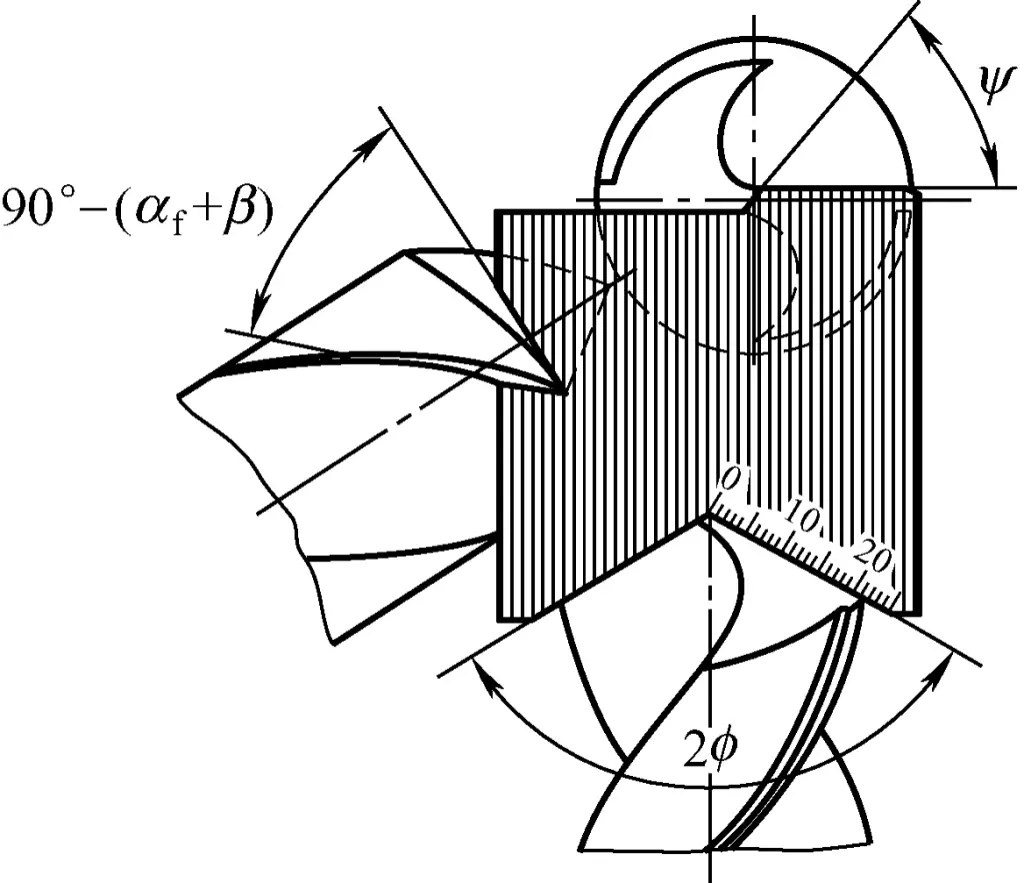
When visually inspecting, hold the cutting part of the drill bit upright and look at it at eye level. Due to the visual difference caused by one main cutting edge being in front and the other behind, the left edge (front edge) often appears higher while the right edge (back edge) appears lower. Therefore, rotate it 180° and look several times. If the results are the same, it indicates symmetry.
The required clearance angle at the outer edge of the drill bit can be directly visually inspected by observing the inclination of the clearance face near the cutting edge at the outer edge. The required clearance angle near the center can be ensured by controlling the appropriate grinding angle of the chisel edge inclination.
2. Sharpening drill bits for drilling holes in thin plate workpieces
When drilling holes in thin plate workpieces, ordinary twist drills cannot be used because their drill points are too high. At the beginning of drilling, due to the poor rigidity of the workpiece, it is prone to deformation and vibration, causing the workpiece to bend downward. When the drill point penetrates the workpiece, the axial force suddenly decreases, causing the workpiece to spring back quickly, making the cutting edge suddenly cut in too much, resulting in plunging or drill bit breakage.
At the same time, after the drill point exits the workpiece, the drill bit loses its centering function, and vibration suddenly increases, causing the drilled hole to be out of round or have large burrs at the hole entrance. In view of these situations, the twist drill must be modified and reground.
(1) Sharpening requirements for thin plate drills
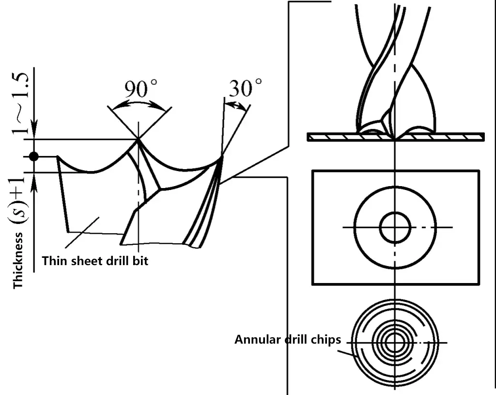
The thin plate drill is a twist drill with its two main cutting edges ground into an arc shape (see Table 2 and Figure 9). The drill point height is ground lower, and the outer edges of the cutting edges are ground into sharp cutting points, with the two outer cutting points 0.5 to 1.5mm lower than the drill point center.
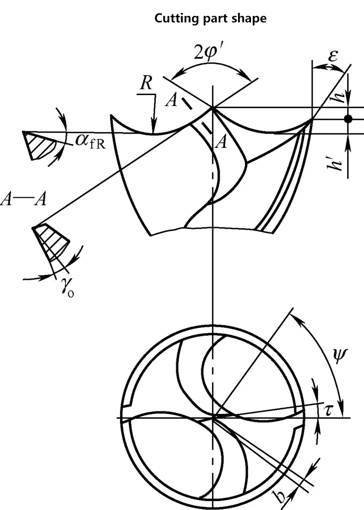
This way, when drilling, the drill point center first cuts into the workpiece, serving as a centering function. Then, taking advantage of the workpiece’s downward bending deformation, the two outer cutting points enter the workpiece. While the drill point center has not yet penetrated the workpiece, the two sharp cutting points have already cut an annular groove on the workpiece and quickly cut out the required hole.
Additionally, when grinding, the two outer cutting points must be at the same height, and the length of the cutting edges from the two cutting points to the drill point center must be consistent. This ensures that the holes drilled in thin plate workpieces meet requirements, with round and smooth holes.
Table 2 Shape and geometric parameters of the thin plate drill cutting section
| Drill diameter D | Chisel edge length b | Point height h | Arc radius R | Arc depth h′ | Inner edge angle 2φ′ | Cutting edge angle ε | Inner edge rake angle γo | Arc relief angle αfR |
| /mm | /(°) | |||||||
| 5~7 | 0.15 | 0.5 | Using single arc connection | >(δ+1) | 110 | 40 | 8~10 | 15 |
| 7~10 | 0.2 | |||||||
| 10~15 | 0.3 | |||||||
| 15~20 | 0.4 | 1 | Using double arc connection | 12 | ||||
| 20~25 | 0.48 | |||||||
| 25~30 | 0.55 | |||||||
| 30~35 | 0.65 | 1.5 | ||||||
| 35~40 | 0.75 | |||||||
Note: δ is the material thickness.
(2) Grinding method for thin plate drills
1) Grind the inner edge point angle 2φ’ to 110°.
2) Modify the drill chisel edge according to Table 2.
3) Grind the arc-shaped cutting edge (also called crescent groove). As shown in Figure 10, first place the drill’s main cutting edge in a horizontal position, with the drill axis forming a 55° angle with the side of the grinding wheel, and the drill tail forming an angle αfR with the horizontal plane (to form the arc relief angle).
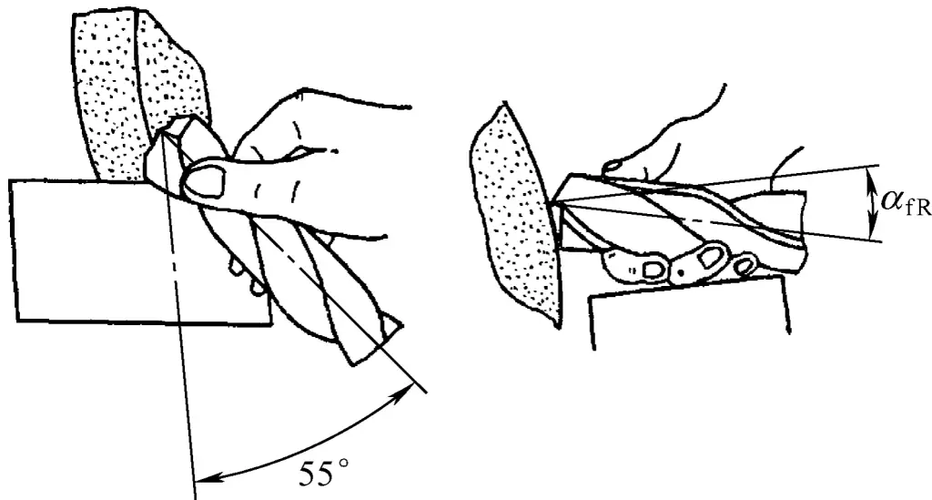
Bring the drill close to the rounded corner of the grinding wheel, with the grinding point roughly at the same height as the center of the wheel. If the wheel’s rounded corner is small, the drill must be swung slightly in the horizontal plane to obtain the required R value.
During grinding, the drill must not be swung up and down in the vertical plane or rotated around its own axis. Otherwise, the chisel edge will become S-shaped, the chisel edge angle will decrease, and the arc shape will not be symmetrical. The outer straight edge should be kept mostly flat to ensure positive relief angles on both sides of the arc edge and an appropriate chisel edge angle. To ensure symmetry of the drill point and the arcs on both sides, when flipping the drill 180° to grind the other arc-shaped cutting edge, its spatial position should remain unchanged.
To achieve this, the following key points of operation need to be mastered: First, the hand holding the drill as a positioning support should rest its wrist or fingers on a stationary object (such as a stop plate) and maintain its position and posture unchanged; Second, the position of the hand holding the drill should not change; Third, the operator’s standing position and operating posture should remain unchanged.
After grinding, the shape and dimensions of each part can be checked for correctness through visual inspection or by using tools such as steel rulers or radius gauges.
3. Usage methods and precautions for common drilling machines
(1) Use of bench drilling machines (bench drills)
1) Structure of a bench drill press
As shown in Figure 11, the spindle speed of a bench drill is generally high and can be adjusted by changing the position of the V-belt on the pulley. The spindle feed motion is manual. To accommodate different workpiece size requirements, the spindle head can move up and down along the column after loosening the locking handle.
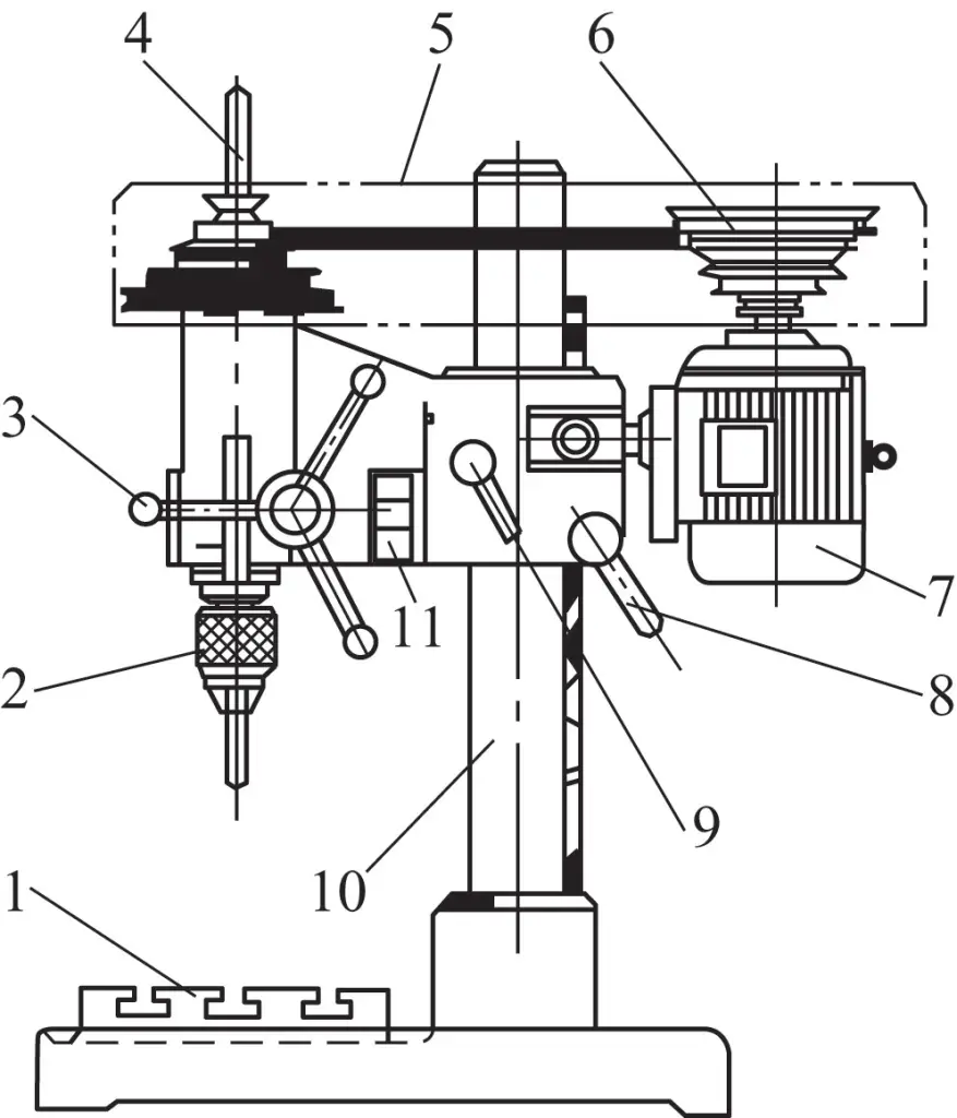
1—Drill press worktable
2—Drill chuck
3—Feed handle
4—Spindle
5—Belt cover
6—Stepped V-belt pulley
7—Motor
8—Elevation handle
9—Locking handle
10—Column
11—Switch
2) How to use a bench drill press
① Stop the machine first, then change the speed.
When changing speed, simply loosen the set screw and push the motor towards the operator to loosen the drive belt, then change the position of the belt on the stepped pulley to achieve the desired speed.
After changing the speed, the motor must be pushed back away from the operator to tighten the drive belt, then tighten the set screw. If the drive belt is not tightened, during drilling, the drill spindle may stop rotating due to insufficient drilling torque caused by belt slippage, which can also easily break the drill bit.
② Loosen the handle, turn the crank, and the drill head can move up and down along the column to adjust the height of the drill bit. After adjustment, the handle must be locked.
③ The spindle must rotate clockwise (i.e., forward rotation) when drilling.
④ It is not allowed to use the drill chuck to clamp cylindrical workpieces for other operations, such as polishing surfaces.
3) Maintenance of bench drill press
- When drilling through holes, a support block must be placed under the workpiece to prevent damage to the worktable surface.
- During use, the worktable surface must be kept clean.
- Lubrication oil should be added regularly.
(2) Use of floor drill press
1) Structural features of floor drill press
As shown in Figure 12, compared to bench drill press, floor drill press has the following advantages:
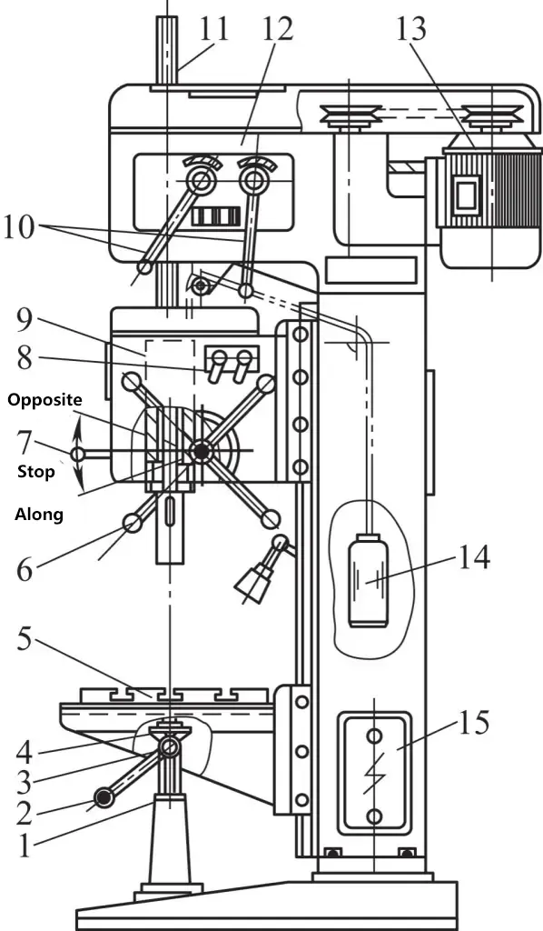
1—Lead screw
2—Lifting handle
3—Small bevel gear
4—Large bevel gear
5—Worktable
6—Feed handle
7—Start handle
8—Feed adjustment handle
9—Feed box
10—Speed change handle
11—Drill rod
12—Gearbox
13—Electric motor
14—Balance weight
15—Control box
- Wide range of drilling diameters.
- Due to the use of a gearbox for speed change, there is a wide range of speeds. By changing the position of the two control handles on the gearbox, the speeds indicated on the nameplate can be obtained.
- By loosening the locking handle and operating the lifting handle, the worktable can be raised, lowered, or rotated (360° rotation possible).
- A cooling pump and cooling motor are installed on the protrusion of the base on the left side of the column. Starting the cooling motor will deliver cutting fluid to cool and lubricate the tool.
Compared to radial drilling machines, the disadvantage of vertical drilling machines is that when processing multiple holes, the workpiece needs to be moved and positioned for each hole. If there are many holes to be processed on one surface, it becomes very inconvenient to use. Therefore, in such cases, using a radial drilling machine with a movable spindle is much more convenient for processing.
2) Precautions for use
- Before operation, thoroughly check if all operating mechanisms are functioning normally. Clean the column guide rails with fine cotton yarn and lubricate according to the specified oil grade.
- The spindle box of the vertical drilling machine must be locked in place before operation.
- Before drilling, the worktable, workpiece, fixture, and cutting tool must be aligned and secured.
- Correctly select spindle speed and feed rate, and do not overload the machine.
- When drilling beyond the worktable, the workpiece must be stably installed. For the Z5140 vertical drilling machine, it is not allowed to operate the speed change handle to change speeds during operation or automatic feeding. If speed change is necessary, it can only be done when the spindle has completely stopped. Installing and removing cutting tools and measuring workpieces must be done while the machine is stopped. It is not permitted to hold the workpiece directly by hand for drilling, and wearing gloves during operation is prohibited. If any abnormal noise is detected during operation, stop the machine immediately to check and eliminate the fault.
(3) Use of radial drilling machines
1) Structural features of radial drilling machines
As shown in Figure 13, the workpiece is installed on the base 8 or on the worktable 9 above the base. The gearbox 5 is mounted on the arm 6, which can rotate around the vertical column 1 and move back and forth along the horizontal guide rail on the arm. These two movements allow the drill rod to be adjusted to any position within the machine’s working range.
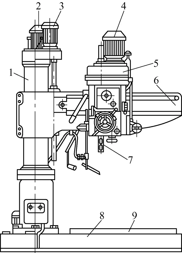
1—Column
2—Arm rotation motor
3—Arm lifting motor
4—Main motor
5—Gearbox
6—Arm
7—Drill rod
8—Base
9—Work table
Therefore, when processing workpieces with multiple holes on a radial drilling machine, the workpiece can remain stationary. By adjusting the position of the arm and gearbox on the arm, it is convenient to align with the hole centers. Additionally, the arm can be raised and lowered along the column, allowing the height of the gearbox to be adjusted to suit the height of the workpiece’s processing area.
2) Precautions for using a radial drilling machine
① Before starting the equipment, it should be operated at low speed first. Only begin working after the hydraulic mechanism, transmission mechanism, and lubrication system are functioning normally.
② When loading or unloading workpieces or fixtures, move the arm away and pay attention to the surrounding environment to prevent collision accidents.
③ The workpiece must be firmly clamped. When drilling through-holes, the bottom surface of the workpiece must be properly supported with blocks to prevent damage to the equipment.
④ When aligning the workpiece position before drilling, loosen the locking device and adjust the length of the protruding spindle according to the drilling depth. The height of the radial drill should be adjusted appropriately, not too high.
The sequence of this operation is: determine the workpiece position, rotate the arm; move the gearbox; lower the spindle to set the tool; lock the arm and gearbox.
⑤ When adjusting the automatic feed for drilling depth, first bring the drill bit in contact with the workpiece, then adjust the feed limit block to the required depth value and lock it.
⑥ During the machining process, the arm and gearbox must be in a clamped state.
⑦ Remember to stop the machine before changing speeds when drilling.
⑧ Be cautious of overloading the drilling machine during operation. If abnormal noises or vibrations occur, stop the machine immediately for inspection and troubleshooting.
⑨During the drilling process, do not stop the machine before the drill bit is withdrawn from the workpiece; when reversing, wait until the spindle stops before starting again.
⑩After drilling is completed, all handles must be placed in the non-working position, the gearbox should be parked close to the column, the arm should be lowered to a suitable position, and then the power should be cut off.
4. Common scribing and drilling operation processes
(1) Scribing the workpiece before drilling
1) Using scribing tools for drilling
- Draw cross-center lines on the workpiece according to the dimensional requirements of the drilling position.
- Use a center punch to make a center punch mark at the intersection of the cross (the punch mark should be small and accurately positioned).
- As shown in Figure 14, draw hole diameter lines (check circle) or check square lines according to the size of the hole, to check and align the drilling position during drilling.
- Enlarge the center punch mark to ensure accurate centering when starting to drill.
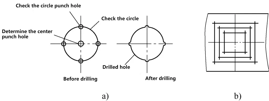
a) Check circle
b) Check square
2) Using templates for scribing and drilling
Figure 15 shows a narrow and long plate that needs drilling, where it’s difficult to use scribing tools (such as height gauges) and scribing aids (such as scribing platforms, V-blocks, etc.) for precise scribing. Therefore, a scribing template should be used. Place the template on the plate, align them, then use a scriber to draw processing circles for the four holes, and use a center punch to make centering marks for drilling.
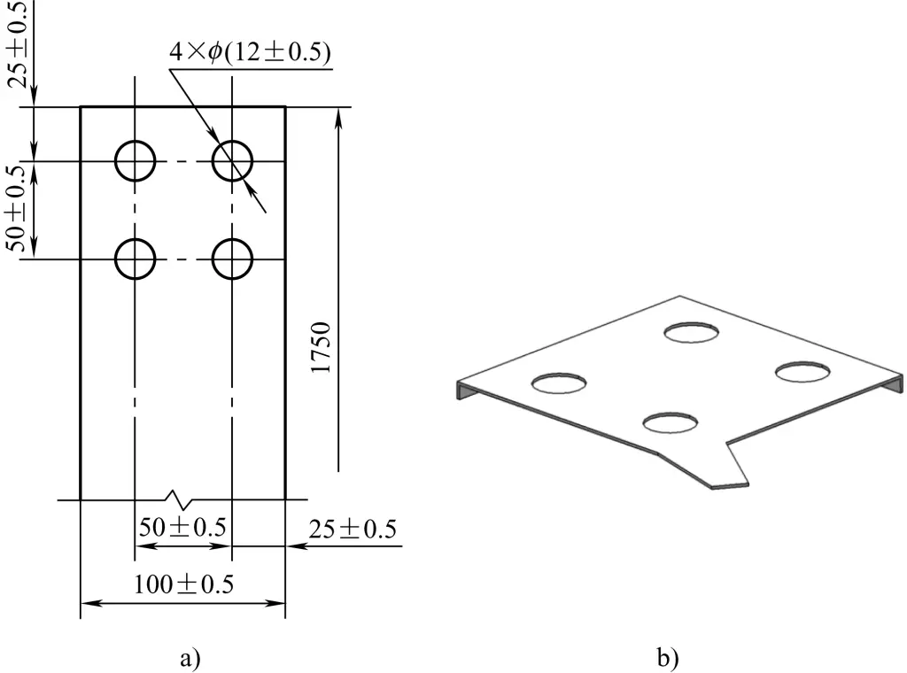
a) Master line drilling dimensions
b) Drilling template
(2) Drill bit clamping
1) Clamping straight shank drill bits
Straight shank drill bits with diameters below ϕ13mm are held in drill chucks. Figure 16 shows the structure and usage method of a common drill chuck.
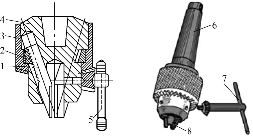
1—Jaws
2—Ring nut
3—Chuck sleeve
4—Chuck body
5—Key
6—Matches with the drill press spindle taper hole
7—Drill press key
8—Self-centering jaws
Figure 17 shows the structure of a quick-change drill chuck. To use it, push the outer sleeve up by hand until it touches the spring ring. Then insert the drill sleeve with the tool into the chuck body. At this point, the steel balls in two symmetrical positions are pushed outward, and the part of the steel balls protruding outside the chuck body enters the annular space at the bottom of the outer sleeve.

1—Drill spindle
2—Sleeve chuck body
3—Locking ring
4—Steel ball
5—Spring clip
6—Sleeve
7—Twist drill
When the notch at the top of the drill sleeve engages with the drive key, its semicircular groove aligns with the position of the steel balls. As the outer sleeve drops, it pushes the exposed part of the steel balls into the semicircular groove of the drill sleeve, locking it in place. This way, the force from the drill spindle is transmitted through the drive key to the interchangeable drill sleeve and tool, enabling cutting.
Using this type of drill chuck allows for tool changes without stopping the machine. Different drill sleeves can be prepared in advance according to the shank sizes of various tools, and the required tools can be assembled with the drill sleeves, ready to start work at any time.
2) Clamping of taper shank drills
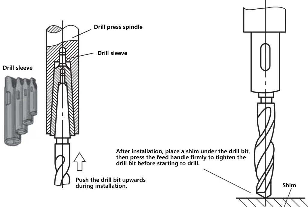
Drills with diameters larger than ϕ13mm are usually Morse taper shank drills. When the drill diameter is smaller, it sometimes cannot be directly fitted with the spindle taper hole of a vertical or radial drill (vertical drill spindle taper holes are usually Morse taper No. 3 or 4, radial drill spindle taper holes are usually Morse taper No. 5 or 6), so several drill sleeves need to be used for adaptation.
There are five sizes of Morse drill sleeves. Usually, the external taper of each size sleeve is one size larger than its internal taper. For example, a No. 1 sleeve has a No. 1 Morse taper internal hole and a No. 2 Morse taper external cone; a No. 2 sleeve has a No. 2 Morse taper internal hole and a No. 3 Morse taper external cone, and so on.
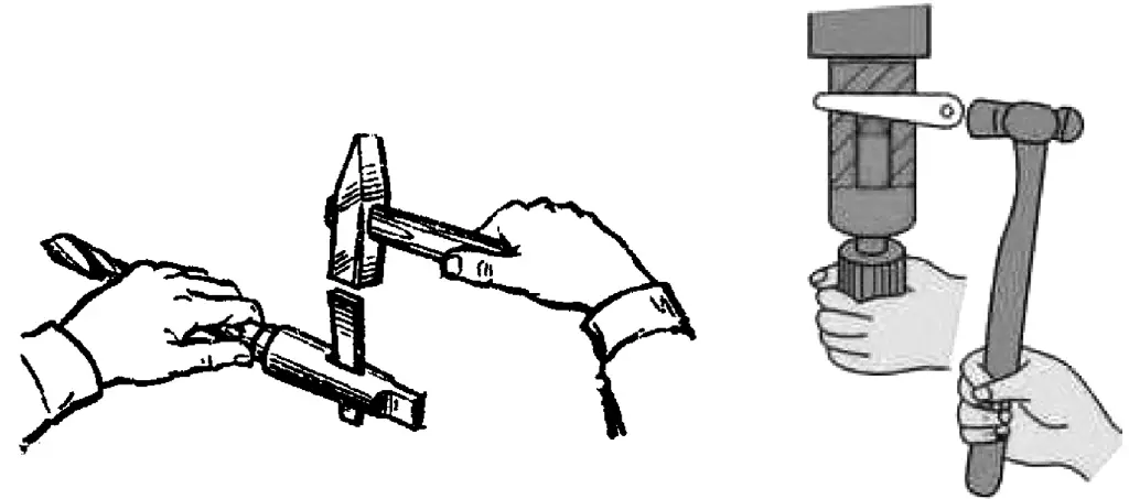
Figure 18 shows the installation method for drill sleeves, and Figure 19 shows the removal method for drill sleeves.
(3) Workpiece clamping
When drilling holes in a workpiece, different clamping (positioning and fixturing) methods should be adopted based on the workpiece’s shape, drilling force magnitude (or hole diameter size), and other factors to ensure drilling quality and safety.
The commonly used basic clamping methods are as follows:
1) Flat workpieces can be clamped using a machine vise.
As shown in Figure 20a, when clamping, ensure that the workpiece surface is perpendicular to the drill bit. When drilling larger diameter holes, the machine vise must be secured with bolts and clamping plates. When drilling through-holes on a workpiece held in a bench vise, place a spacer block under the workpiece to create clearance for the drill bit exit, preventing damage to the vise.
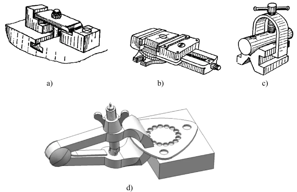
a) Using a machine vise
b) Using a V-block
c) Using a step clamp
d) Using a hand vise
2) Cylindrical workpieces can be clamped using a V-block.
As shown in Figure 20b, when clamping, ensure that the drill bit’s axis aligns with the symmetrical center plane of the V-block to ensure that the center line of the drilled hole passes through the workpiece’s axis.
3) For larger workpieces or those inconvenient to clamp with a machine vise, they can be directly secured to the drill table using clamping plates, bolts, and nuts. As shown in Figure 20c, when setting up the clamping plate, note that the spacer should be as close to the workpiece as possible to increase the clamping force on the workpiece and prevent the clamping plate from bending or deforming.
The clamping plate bolts should be as close to the workpiece as possible, and the spacer should be slightly higher than the clamping surface of the workpiece to ensure greater clamping force and prevent the workpiece from moving during the clamping process. When the clamping surface is a machined surface, use a protective pad to prevent indentation marks.
4) As shown in Figure 20d, when drilling small holes in small workpieces or thin plates, the workpiece can be placed on a locating block and clamped with a hand vise.
(4) Selection of cutting parameters
1) Concept of cutting parameters
① Cutting speed v
The cutting speed for drilling refers to the linear speed of a point on the drill bit diameter during drilling. The relationship between cutting speed v and rotational speed n is
v =πdn/1000
Where d is the drill bit diameter (mm); n is the spindle rotation speed (r/min).
② Feed rate f
Feed rate refers to the distance the drill bit moves along the spindle axis for each revolution of the spindle.
2) General methods for selecting rotational speed and feed rate
For the surface roughness of drilled holes, cutting speed usually has a greater impact than feed rate; while for drilling efficiency, feed rate has a greater impact than cutting speed. Generally, feed rate has a greater impact than rotational speed. The rotational speed and feed rate for drilling should be considered based on factors such as workpiece material hardness, strength, hole diameter, depth, and required surface roughness of the processed hole.
Generally: When drilling soft materials such as soft steel (mostly low carbon steel) and non-ferrous metals, the rotational speed can be relatively high, and the feed rate can be relatively large; when drilling hard materials (such as high carbon steel, cast iron), the rotational speed should be relatively low, and the feed rate should be relatively small.
When drilling small diameter holes, the rotational speed should be higher, and the feed rate should be smaller; when drilling large diameter holes, the rotational speed should be lower, and the feed rate should be larger; for deep hole drilling, both cutting speed and feed rate should be selected at lower values. For specific selection, refer to relevant cutting handbooks.
(5) Test drilling
1) Drill positioning
The drill positioning referred to here is the process of placing the drill tip into the center punch mark before drilling. The specific method is: Before starting the drill press, lower the drill bit, first place the drill tip into the center punch mark, then raise the drill bit, manually rotate the drill bit counterclockwise, and lower the drill bit again. If the drill tip accurately falls into the center punch mark again, it indicates that the drill tip is aligned with the hole center (observe in two perpendicular directions).
If the drill tip does not fall into the center punch mark, it indicates an error in alignment. Slightly move the workpiece position and repeat the positioning process until the drill tip falls into the center of the center punch mark.
2) Test drilling
As shown in Figure 21, after correct positioning, a shallow pit should be drilled first, with a diameter of about 1/3 of the actual hole diameter. If the drilled conical pit is not concentric with the drawn hole circumference line or not equidistant from the edges of the square line, it indicates that the hole position is off-center. At this time, the workpiece can be moved or the drill press spindle can be moved (when drilling with a radial drill) for adjustment.

The key points for adjustment are: Lower the drill bit with a very small feed rate while slowly pushing the workpiece in the same direction as the deviation, gradually adjusting. It should also be noted that if the outer circle of the test-drilled conical pit has already reached the hole diameter size, and the hole position is still skewed, it will be difficult to correct further.
(6) Manual feed operation
Once the test drilling meets the position requirements for the hole, drilling can continue.
As shown in Figure 22, when manually feeding, the force applied should not cause the drill bit to bend, to avoid skewing the hole axis; when drilling small diameter holes or deep holes, the feed force should be small, and the drill should be frequently retracted to remove chips, to prevent chip clogging and drill bit breakage. When the drilling depth reaches 3 times the diameter, it is necessary to retract the drill to remove chips; when the hole is about to be drilled through, the feed force must be reduced to prevent sudden excessive feed, which increases cutting resistance and causes drill bit breakage or accidents where the workpiece rotates with the drill bit.

5. Drilling methods for different types of holes
(1) Drilling thin plate workpieces
1) Drilling with thin plate drill bits
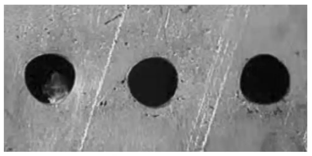
When drilling thin plates with standard twist drill bits, the drill bit easily loses its centering control, resulting in polygonal holes (see Figure 23). If the feed rate is large, “plunging” or drill bit breakage accidents may occur. Therefore, thin plate drill bits should be used for drilling thin plates, as shown in Figure 24.
2) Method of cutting large holes in thin plates using a cutting rod
As shown in Figure 25, when making large holes in thin plates, the cutting rod method can be used. Before drilling, the workpiece should be firmly clamped. During drilling, the spindle speed should be slow and the feed rate should be small. When the workpiece is about to be cut through, stop feeding, and the uncut portion can be knocked off with a hammer.
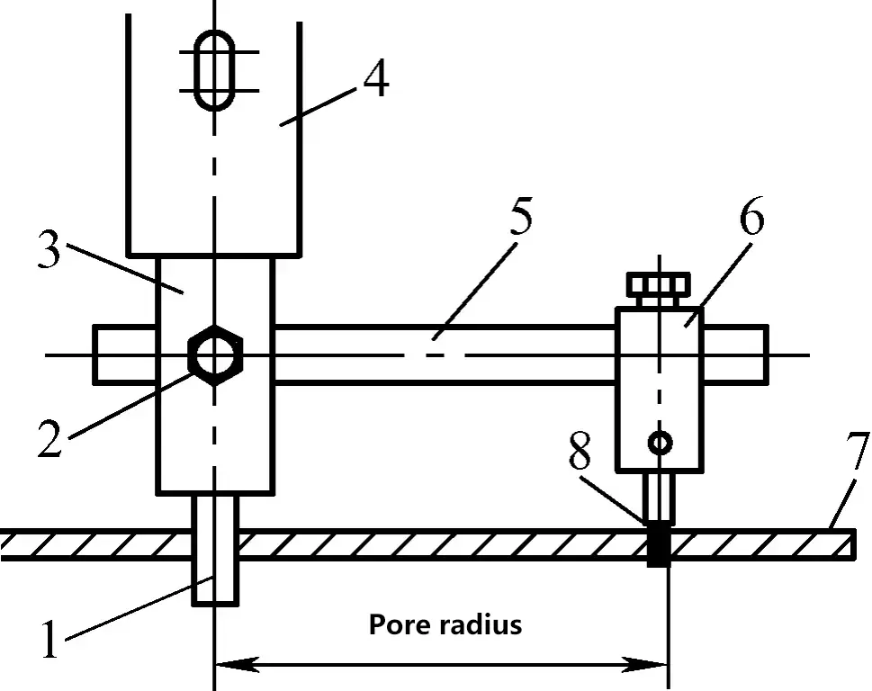
1—Guide rod
2—Fixing screw
3—Cutting rod
4—Drill press spindle
5—Support
6—Tool holder
7—Thin steel plate
8—Cutting tool
(2) Drilling on cylindrical outer surface
As shown in Figure 26, when drilling holes perpendicular to the axis and through the center on the outer surface of a cylindrical workpiece, first place the cylindrical workpiece on a V-shaped iron, then do the following:

1—Cylindrical workpiece
2—Drill bit
3—Pressure plate
4—Shim
5—Square ruler
- Use the drill tip to locate the center position of the V-shaped iron.
- Use a square ruler to find the center line of the workpiece end face.
- Align the drill tip with the center of the hole, perform a test drill and then drill the hole.
If high precision is required for the drilled hole, the workpiece should also be properly fixed.
(3) Drilling bridging holes
To prevent relative displacement of combined parts, pins or screws are often used for stopping or fixing, as shown in Figure 27. This requires drilling holes between two combined parts, commonly known as drilling bridging holes.
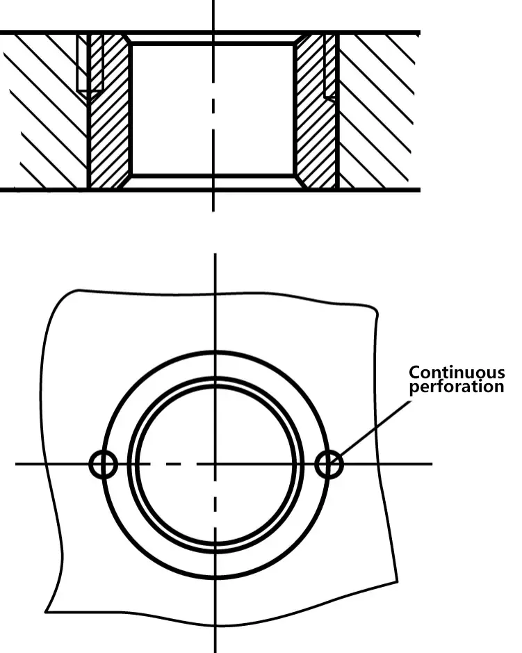
When drilling bridging holes, the drill bit often tends to deviate towards one side of the part, especially when the two parts are made of different materials. The drill bit easily deviates towards the softer material part, resulting in a larger half-circle hole on the soft material part and a smaller half-circle hole on the hard material part. Therefore, to prevent or reduce hole deviation, the following measures can be taken simultaneously:
Measure 1: When punching a center mark before drilling, the punch mark should be slightly biased towards the harder material side.
Measure 2: When the depth of the hole to be drilled is not large, try to use a short drill bit or shorten the length of the drill bit protruding from the chuck, just slightly longer than the hole depth. This increases the rigidity of the drill bit and reduces its bending during the drilling process.
Measure 3: Grind the chisel edge of the drill bit to less than 0.5mm, thereby reducing the axial resistance of the drill center chisel edge part. This not only makes it easier to accurately position the drill center when starting, but also reduces deviation due to the sharpness of the drill bit.
(4) Matching drill holes
During on-site installation or maintenance work, it is often necessary to match drill holes, as shown in Figure 28. From Figure 28, we can see that the holes in the equipment base are already made during manufacturing, which requires drilling bolt connection holes in the installation base frame (channel steel) through the matching drill hole method.
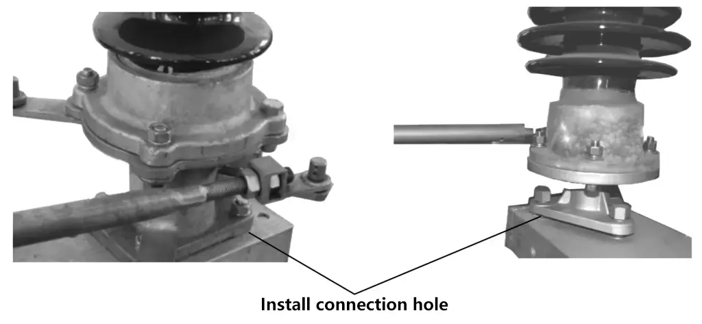
Common methods for matching drill holes during installation work include:
1) After measuring the position of existing holes (hole diameter and spacing), mark the hole diameter lines and hole position lines on the surface to be drilled (such as the upper surface of the installation channel steel) and then proceed with drilling.
2) Use the marking method (refer to Unit Three Marking for marking details) to determine the center of the matching drill hole, then proceed with drilling.
3) Align the two parts to be drilled together in the correct position and clamp them together. Then, using a drill bit with the same diameter as the existing hole, guide it through the existing hole to create a shallow pit marking the position of the hole to be drilled on the surface to be processed (such as the upper surface of the installation channel steel). Remove the part with the existing hole and then proceed with drilling.
(5) Using drill templates for drilling operations
When drilling holes in batches, drill templates can be used as guiding tools for drilling. This method not only improves drilling efficiency but also ensures drilling quality requirements, as shown in Figure 29.
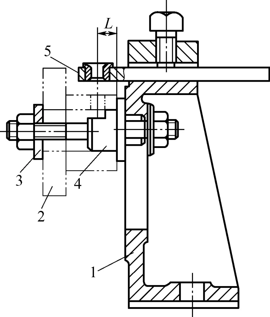
1—Drill body
2—Workpiece
3—Open washer
4—Center shaft
5—Drill template
(6) Small hole drilling process
1) Problems in small hole drilling
- Small hole diameter results in insufficient drill strength and difficulty in chip removal, making the drill bit prone to breakage.
- As mentioned earlier, when drilling small holes, a faster rotation speed should be used. The cutting temperature at the contact area between the drill bit and the workpiece is relatively high and difficult to dissipate heat, causing the drill bit to wear out quickly.
- During drilling, manual feed is generally used, making it difficult to maintain uniform feed force. Slight inattention can easily damage the drill bit.
- The drill bit has poor rigidity and is easily bent, especially when the drill tip encounters high points or excessively hard spots, causing the drill bit to deviate from its original position. This not only results in skewed hole positions but also easily breaks the drill bit.
2) Common methods for small hole drilling
Different requirements for small hole processing lead to different processing methods, so the drilling process plan should be determined based on specific circumstances. Below are several methods and precautions for drilling small holes.
① Choose a higher precision drilling machine. Higher precision drilling machines have better spindle rotation accuracy, resulting in less drill bit wobble and reduced axial force during drilling, which helps improve drilling stability.
② First use a center drill to create a centering hole, then use a small diameter drill bit for drilling.
③ When the drill bit diameter is too small to be clamped by a universal drill chuck, do not wrap the drill shank with sandpaper or paper to thicken it for clamping. Instead, use a small drill chuck or a specialized drill chuck. There are many types of specialized drill chucks, but their clamping principles are basically the same. For example, an elastic drill chuck as shown in Figure 30 can be used to clamp small drill bits.
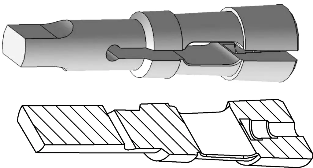
When using the elastic drill chuck shown in Figure 30, select the outer taper and dimensions according to the diameter of the drill bit to be clamped. The inner hole d should be 0.05mm larger than the diameter of the drill bit being clamped.
First, insert the drill chuck into the drilling machine spindle taper hole or standard drill sleeve, then install the drill bit, and finally tighten the drill chuck from the bottom end. At this point, the drill chuck is subjected to radial pressure, forcing the elastic opening to contract and clamp the drill bit tightly.
④ The cutting speed for drilling small holes can be selected based on experience. For general precision drilling machines, when the drill bit diameter is 2-3mm, the rotation speed should be 1500-2000r/min; for drill bit diameters below 1mm, the recommended rotation speed is 2000-3000r/min.
⑤When starting to drill small holes, the feed force should be small to prevent the drill bit from bending and slipping, ensuring the correct initial position of the hole.
⑥When feeding small holes, hand feel should be properly controlled. When the drill bit bounces, intermittent feeding should be applied with a smaller feed force, allowing the drill bit and feed mechanism to buffer using their own rebound to prevent the drill bit from breaking.
⑦When drilling small holes, frequently retract the drill to remove chips and add cutting fluid.
6. Drilling Examples
As shown in the previous image, it is a 5mm thick sample plate made of A3 steel. The marking method before processing has been detailed in Unit 3. The following is a specific analysis of the key technical process – drilling – in the processing of this sample plate:
1) Due to the large overall size and large hole diameters (such as ϕ35mm, R34mm, R19mm three holes) of this sample plate, it cannot be clamped and drilled on a bench drill or vertical drill. After analysis, drilling can only be done on a radial arm drill.
2) In addition to the holes marked on the drawing that need to be processed, this sample plate also implies the processing of “relief holes”. That is, small drill bits (ϕ5mm or ϕ6mm drills are used here) are used to drill holes in the inner cavity of the sample plate, then flat chisels or slot chisels are used to chisel the inner cavity into shape, preparing for subsequent filing. The relief process for this sample plate is shown in Figure 31.
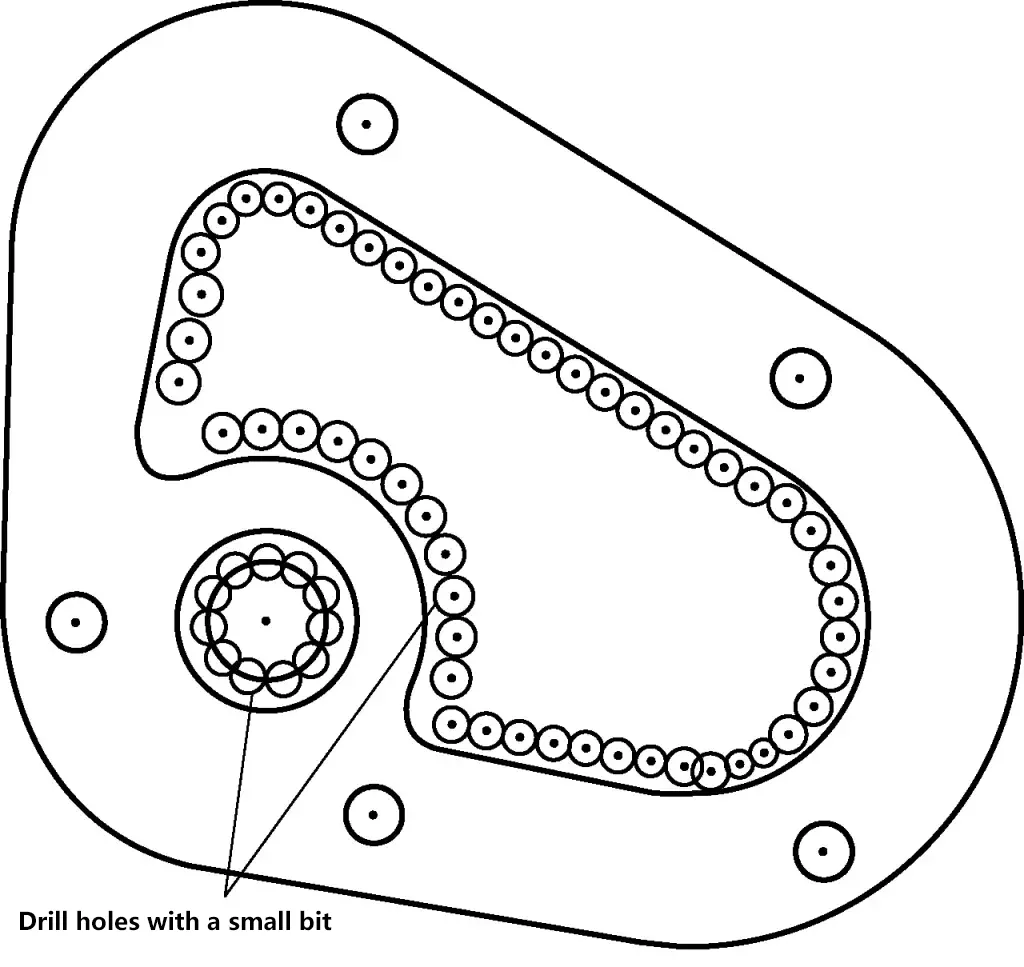
3) The idea is that if this sample plate can be reasonably positioned and safely clamped on the radial arm drill, then all the holes in the sample plate can be processed at once without the need for secondary clamping. For this purpose, the T-slot of the drill work table was used for installation as shown in Figure 32.

1—Pressure plate
2—Drill work table
3—Workpiece being processed
4—Pressure plate nut
5—T-bolt
6—Hardwood block
4) As shown in Figure 32, place a flat hardwood board of certain thickness (generally greater than 20mm) under the workpiece being processed, then insert the T-bolt into the T-slot of the drill work table, press down the pressure plate, and tighten the pressure plate nut. This completes the installation of the workpiece on the drill.
5) Several issues that need attention during the installation of the workpiece are:
①The selected hardwood board should be flat on both the top and bottom surfaces. Otherwise, during the clamping process, it will not only cause deformation of the workpiece being processed but also affect the safety and stability of drilling.
②Reasonably layout and position the pressure plates. As shown in Figure 32, four pressure plates are laid out according to the shape and size of the workpiece, ensuring that the workpiece remains stationary during the drilling process while avoiding the areas of the workpiece that need to be drilled.
③The tightening sequence and torque of the pressure plate nuts should be appropriate. Like tightening grouped bolts, not only should they be tightened diagonally, but the nuts should also be tightened gradually in stages; the tightening force should not be too large or too small. Too small affects safe positioning, while too large will cause workpiece deformation.
6) As the plate is relatively thin (5mm thick), thin plate drill bits should be used for drilling.
7) Drilling the R34mm hole. Since R34mm is relatively large, directly drilling with a ϕ68mm drill bit is neither safe nor economical. Therefore, there are two methods for processing the R34mm hole:
①First use a small drill bit (ϕ5mm or ϕ6mm) to drill relief holes (see Figure 31), then use a half-round file or round file for processing.
②As mentioned earlier, use the method for drilling large holes in thin plates.
8) The processing of ϕ35mm and R19mm holes can be done using the following two methods:
①Directly process using ϕ35mm and ϕ38mm thin plate drills. As this method is less safe and economical, it should be avoided if possible.
②First use small drill bits (ϕ5mm or ϕ6mm) to drill relief holes (see Figure 31), then use a half-round file or round file for processing.
9) When drilling the five ϕ11mm holes, thin plate drill bits should be used.
10) It is strictly prohibited to use automatic tool feed during drilling and reaming.
7. Drilling Quality Analysis (see Table 3)
Table 3 Analysis of Causes for Drilling Problems
| Problem Occurred | Main Cause Analysis | Preventive Measures | ||
| Hole diameter and roundness out of tolerance during drilling | The two cutting edges of the drill bit are unequal in length and asymmetrical | Grind the drill bit to meet requirements | ||
| Excessive drill bit wobble | Excessive drill spindle wobble | Repair the drilling machine | ||
| Drill bit installed at an angle in the drill chuck | Install the drill bit correctly | |||
| Drill shank worn, roundness or cylindricity out of tolerance | Replace the drill bit | |||
| Vise moves during drilling | Center punch mark too small, drill bit’s chisel edge not entering the center punch mark, causing vise to move when manually applying pressure to start drilling | Enlarge the center punch mark after correct positioning to allow the drill bit to center properly | ||
| Poor contact between vise base and drill table surface, causing vise movement | Repair the vise and drill table | |||
| Insufficient grip on vise handle, causing vise movement during drilling | Grip the vise correctly (use T-bolts to secure the vise if necessary) | |||
| Hole position accuracy out of tolerance during drilling | Marking error | Check and verify after marking | ||
| Inaccurate center punch mark (not at the intersection of two centerlines) | Correctly position the center punch mark using the proper method | |||
| Workpiece moves during drilling | Vise moves during drilling (as mentioned above) | |||
| Workpiece not firmly clamped | Clamp the workpiece firmly using the correct method | |||
| Drilling axis is tilted | Drill bit is not perpendicular to the workpiece surface | 1) Check the perpendicularity of the drill bit to the workpiece surface using a square perpendicularity; 2) Check the parallelism of the workpiece surface with the top of the vise jaws using a steel ruler or scribing block | ||
| Drill hole is bent | Manual feed rate is too high | Select the manual feed rate according to the drilling process requirements | ||
| Forcibly correcting after discovering the hole center is off when starting to drill | During test drilling, adjust the misaligned hole position according to hole positioning principles | |||
| Inner wall roughness of the hole is too high | Drill bit cutting edge is not sharp | Sharpen the drill bit to meet the cutting edge sharpness requirements | ||
| Excessive vibration during drill bit cutting process | Excessive spindle vibration | Repair the drilling machine | ||
| Drill bit not properly clamped | Re-clamp the drill bit | |||
| Drill bit relief angle is too large | Grind the drill bit relief angle according to requirements | |||
| Feed rate is too high | Choose a reasonable drilling feed rate based on factors such as workpiece material and hole diameter | |||
| Insufficient cooling and lubrication during drilling | Apply cutting fluid timely during drilling | |||
| Drill bit cutting edge is worn | Drilling speed is too high | Select drilling speed according to drilling process requirements | ||
| Insufficient cooling and lubrication | Provide sufficient cooling and lubrication | |||
| Failure to select appropriate drill bit cutting angle based on material and hardness | Select drill bit cutting angle according to drilling process requirements | |||
| Drill bit breakage | Drill bit cutting edge is not sharp | Sharpen the drill bit | ||
| Workpiece is loose or vise moves, forcibly twisting and breaking the drill bit | Securely clamp the workpiece according to process requirements, prevent vise movement during drilling (if necessary, use T-bolts to fix the vise) | |||
| Excessive feed force | Select feed force based on material and hole diameter | |||
| Failure to select appropriate speed and feed rate | Select drilling speed and feed rate according to drilling process requirements | |||
| Failure to reduce feed rate when the hole is about to break through | Reduce feed rate when the hole is about to break through | |||
| Chips clog the flutes | Regularly retract the drill to clear chips | |||
8. Safety operating procedures for drilling
- When drilling, shirt sleeves must be tightened, gloves are not allowed, and cotton waste or rags should not be held in hands.
- The workpiece must be securely clamped to prevent displacement during drilling. Holding the workpiece by hand while drilling is not allowed.
- When changing speeds on the drill press, stop the machine first, then change the speed.
- Do not use hands to clear chips or blow chips with your mouth. Use hooks and brushes, and only clear chips when the machine is stopped.
- When drilling through-holes, take appropriate measures (such as placing a backing block under the workpiece) to prevent damaging the table or vise.
- When applying axial feed, the feed pressure should not be too high, and pay attention to retracting the drill to clear chips at appropriate times.
- When the hole is about to break through, the drilling resistance decreases, and the feed pressure should be reduced accordingly to prevent accidents such as drill bit damage or workpiece ejection due to the drill bit getting caught on the hole edge.
- Do not attempt to grab the drill chuck before the drill press has come to a complete stop. Always use the chuck key to tighten or loosen the drill chuck, and do not use other tools to strike it.
- Do not place measuring tools or other unrelated tools and fixtures on the drill press work table.

