1. Striking the arc
To start welding, you first need to strike the arc, which can be done by either the scratch method or the direct strike method.
(1) Scratch method
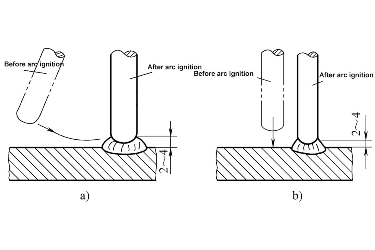
First, align the end of the electrode with the workpiece, then twist your wrist slightly to gently scratch the electrode on the surface of the workpiece, similar to striking a match. Do not apply too much force, then lift the electrode 2~4mm to generate an arc in the air.
After igniting the arc, the electrode should not be too far from the workpiece, generally not exceeding 10mm, and should not go beyond the weld area. Then twist your wrist back to a level position, maintain a certain arc length, and begin welding. The scratch method is shown in Figure 5-15a.
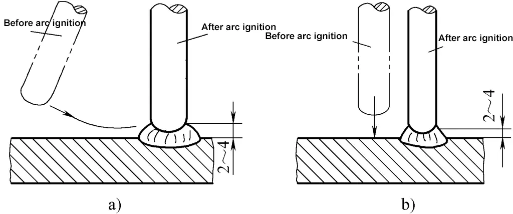
a) Scratch method
b) Direct strike method
(2) Direct strike method
First, align the end of the electrode with the workpiece, then bend your wrist down slightly to lightly touch the workpiece with the electrode, then quickly lift it by 2~4mm to generate an arc. After striking the arc, level your wrist and maintain a certain arc height to start welding, as shown in Figure 5-15b for the direct striking method.
The scratch start method is easy for beginners to master, but improper operation can damage the surface of the workpiece. The direct striking method is more difficult for beginners to master, and improper operation can cause the electrode to stick to the workpiece or cause large chunks of flux to fall off when too much force is used.
(3) Precautions for striking an arc
The area for striking an arc should be clean, free of oil, rust, and other debris to avoid affecting conductivity and causing oxides in the weld pool, which can lead to porosity and slag inclusion in the weld. To facilitate arc striking, the electrode should expose the welding core to help conduct electricity.
The arc should be struck within the weld seam to avoid damaging the surface of the workpiece when striking the arc. The arc striking point should be 10~20mm ahead of the welding point (or the previous ending point of the arc). After igniting the arc, move the electrode to the ending point of the previous electrode to start welding, which can prevent porosity and poor appearance due to the lower temperature of the first few drops of molten metal from the new electrode, especially with basic electrodes.
2. Electrode manipulation
(1) Basic movements of electrode manipulation
When welding with an ignited arc, the electrode must perform three basic movements to achieve a well-formed weld seam and stable arc burning: advancing the electrode towards the weld pool, swinging the electrode laterally, and moving the electrode forward. The three movements of electrode manipulation are shown in Figure 5-16.

1—Electrode feeding
2—Electrode oscillation
3—Electrode advancement
1) The action of feeding the electrode into the molten pool.
During the welding process, the electrode gradually melts and shortens under the heat of the arc, causing the arc length to increase. To maintain a stable arc and a certain arc length, the electrode must be gradually fed towards the direction of the molten pool. To achieve this, the feed rate of the electrode should be equal to the melting rate of the electrode.
If the electrode feed rate is too fast, the arc length will quickly shorten, causing the electrode to contact the workpiece and create a short circuit; if the feed rate is too slow, the arc length will increase until the arc breaks. Practice has shown that a uniform electrode feed rate and constant arc length are important conditions for obtaining excellent welds.
2) Lateral swinging action of the electrode.
During the welding process, to obtain a certain width of the weld and improve the internal quality of the weld, the electrode must have appropriate lateral oscillation. The amplitude of the oscillation is related to the required width of the weld and the diameter of the electrode; the greater the oscillation, the wider the weld.
Lateral oscillation inevitably reduces the welding speed and increases the heat input to the weld. The normal width of a weld is generally 2 to 5 times the diameter of the electrode. For some materials that require low heat input, such as austenitic stainless steel and 3.5Ni low-temperature steel, lateral oscillation of a single pass weld is not advocated.
3) Forward movement of the electrode.
During the welding process, the speed of the electrode moving forward should be appropriate. If the electrode moves too fast, the arc cannot melt enough electrode and base metal, causing welding defects such as too small a weld cross-section and incomplete penetration. If the electrode moves too slowly, too much molten metal accumulates, causing overflow and poor weld formation, and due to concentrated heat, thin workpieces are prone to burn-through, while thick workpieces may overheat, reducing the overall performance of the weld metal.
Therefore, the speed of the electrode moving forward should be properly controlled based on different factors such as current size, electrode diameter, thickness of the workpiece, assembly gap, welding position, and material of the workpiece.
(2) Electrode manipulation method
The so-called electrode manipulation method refers to the technique of moving the electrode by the welder during the welding process. It, along with the electrode angle and the three movements of electrode motion, constitutes the welding operation technique. The electrode manipulation method is an important factor in obtaining excellent welds and is an important indicator of a welder’s operational skills.
1) Straight-line electrode manipulation method.
During welding, maintain a certain arc length and move forward in the direction of welding without swinging, as shown in Figure 5-17a. Since the electrode does not swing laterally, the arc is more stable, this method can achieve greater penetration depth and faster welding speed, and is beneficial for welding easily overheated workpieces and thin plates, but the weld formation is narrower, suitable for butt welding of plates with thicknesses of 3~5mm without beveling, the first layer of multi-layer welding, and multi-pass welding.

a) Straight-line
b) Straight-line reciprocating
2) Straight-line reciprocating electrode manipulation method.
During the welding process, the end of the electrode moves back and forth in a straight line along the direction of the weld, as shown in Figure 5-17b. In actual operation, the arc length varies.
When welding, maintain a short arc, after welding a short section, the arc lengthens, jumps forward, waits for the molten pool to slightly solidify, and the electrode returns to the molten pool for intermittent welding. This method has a fast welding speed, narrow weld seam, and fast heat dissipation, suitable for thin plates and bottom layer welding with larger butt gaps.
3) Sawtooth oscillation method.
During the welding process, while the end of the electrode moves forward, it continuously makes a sawtooth oscillation laterally, as shown in Figure 5-18.

a) Regular sawtooth
b) Slanted sawtooth
When using the sawtooth oscillation method, pause slightly on both sides, the duration of the pause depends on the shape of the workpiece, current size, weld width, and welding position, mainly to ensure good melting on both sides of the groove and to prevent undercutting. The purpose of the lateral oscillation of the electrode is mainly to control the flow of molten metal in the weld and to obtain the necessary weld width for good weld formation.
Because this method is easy to operate, it is widely used in production, mostly for welding thicker steel plates. Its specific applications include flat welding, vertical welding, overhead butt joints, and vertical fillet joints.
4) Crescent oscillation method.
During the welding process, the end of the electrode makes a crescent-shaped lateral oscillation along the welding direction (similar to the sawtooth shape), as shown in Figure 5-19. The speed of the oscillation should be determined based on the weld position, joint type, weld width, and welding current size. To ensure good fusion on both sides of the weld and avoid undercutting, pay attention to the dwell time at both ends of the crescent.

a) Crescent shape
b) Reverse crescent shape
Using the crescent weaving method for welding, the heating time of the molten pool is relatively long, the metal melts well, making it easy for gases in the molten pool to escape and slag to float up, which can eliminate porosity and slag inclusion, resulting in better weld quality. However, since the melted metal concentrates towards the center, it increases the excess height of the weld, thus it is not suitable for narrow vertical welds.
When butt joint fillet welding, to avoid excessive weld metal and to ensure penetration on both sides, sometimes the reverse crescent weaving method is used, as shown in Figure 5-19b. The crescent weaving method is suitable for flat, vertical, overhead, and T-joint fillet welding of thicker steel plates.
5) Triangle Weaving Method.
During the welding process, the end of the electrode moves forward while making continuous triangular movements. The triangle weaving method can be divided into regular triangle and oblique triangle types, depending on the application, as shown in Figure 5-20.

a) Regular triangle
b) Oblique triangle
The equilateral triangle weaving method is only applicable to butt welds with open grooves and vertical welds of T-joints. Its characteristic is that it can weld a thicker weld section at one time, the weld is not easy to produce pores and slag inclusion, which is conducive to improving welding productivity. When the inner layer is restricted by the inclined surfaces on both sides of the groove and the width is small, it is necessary to pause slightly at the triangle fold to facilitate full melting on both sides and avoid slag inclusion.
The oblique triangle weaving method is suitable for flat and overhead position T-joint welds and transverse welds with grooves. Its characteristic is that it can control the flow of molten metal by swinging the welding rod, which helps to form a good weld, reduce the internal pores and slag inclusion of the weld, and is beneficial to improve the intrinsic quality of the weld.
The application of the two triangle weaving methods should be determined according to the specific situation of the weld, such as pausing at the triangle fold during vertical welding; the weaving speed at the turning part of the oblique triangle should be slower. If these actions are well coordinated, good weld formation can be achieved.
6) Circular weaving method.
During the welding process, the end of the welding rod continuously makes circular movements and moves forward continuously, as shown in Figure 5-21.
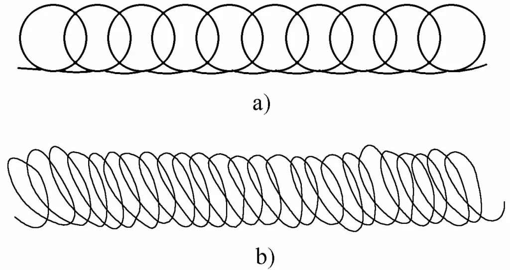
a) Regular circular form
b) Oblique circular form
The regular circular weaving method shown in Figure 5-21a is only suitable for flat welds of thicker workpieces. Its advantage is that the weld pool metal has enough heat to keep the weld pool existing for a longer time, which facilitates the precipitation of gases such as oxygen and nitrogen in the pool, and also facilitates the floating of slag, which is beneficial to improving the intrinsic quality of the weld.
The oblique circular weaving method shown in Figure 5-21b is suitable for flat and overhead position T-joint and butt joint transverse welds. Its characteristic is that it helps to control the phenomenon of molten metal flowing downward due to gravity, which is conducive to the formation of the weld. At the same time, it can slow down the cooling rate of the weld pool, allowing gases in the pool to escape and slag to float, which is beneficial to improving the intrinsic quality of the weld.
7) Figure 8 weaving method.
During the welding process, the end of the electrode continuously moves in a figure 8 pattern and keeps moving forward, as shown in Figure 5-22. This weaving method is relatively difficult to master and is suitable for wider butt welds and vertical surface welds. When welding the surface layer of a butt vertical weld with this method, the weaving technique needs to be flexible, and the weaving speed should be faster, which can achieve a finer, uniform, and aesthetically pleasing weld surface.

The weaving methods introduced above are just a few of the most basic methods. In actual production, welders often adopt different weaving methods according to their own habits and experience when welding the same joint form, and they can achieve satisfactory welding results.
3. Starting, jointing, and finishing
(1) Starting the weld
Starting the weld refers to the operation at the beginning of welding. Since the temperature of the workpiece is low before welding, the arc cannot stabilize immediately after arc initiation, so the starting part often has defects such as shallow penetration, porosity, incomplete fusion, insufficient width, and excessive weld buildup.
To avoid and reduce these phenomena, the arc should be slightly lengthened after arc initiation, the end of the weld should be appropriately preheated, and the weaving should be repeated several times to achieve the required depth and width before adjusting to the proper arc length for normal welding.
For starting a circular weld, since the end of the weld will be finished here, the external dimensions are not required, but it is mainly required to have good penetration and fusion, and the start should be thinner to facilitate a good transition when finishing.
For important workpieces and critical welds, if conditions permit, it is advisable to use a start plate to lead the unacceptable part of the weld out of the workpiece, which is removed after welding.
(2) Weld joint
In manual metal arc welding operations, weld joints are inevitable. The quality of the weld joint not only affects the appearance of the weld but also its quality. The technology of weld joints is shown in Table 5-11.
Table 5-11 Weld Joint Techniques
| Joint Method | Schematic Diagram | Operating Techniques |
| Intermediate Joint |  | Start the arc about 10mm in front of the crater, with the arc length slightly longer than normal welding arc length, move back to the crater, lower the arc and sway slightly, then move forward to weld normally |
| Back-to-back Joint |  | Start welding slightly lower at the beginning of the weld, the subsequent weld must start the arc slightly ahead of the previous weld’s starting point, then slightly lengthen the arc, gradually leading it to the start of the previous weld and covering this start, weld flat, then move in the direction of welding |
| Opposite joint |  | When welding from the back weld seam to the crater of the first weld seam, slow down the welding speed, fill the crater of the first weld seam, and then weld forward slightly faster before extinguishing the arc. |
| Segmented back-step joint |  | When the back weld seam approaches the start of the front weld seam, change the angle of the electrode so that it points towards the start of the front weld seam, elongate the arc to form a molten pool, then lower the arc and return to the original molten pool to extinguish the arc. |
(3) Crater filling of the weld seam
Refers to the method of crater filling used when a weld seam ends. The crater filling of a weld seam is different from the extinguishing of the arc after each electrode is used up. Normally, each used-up electrode leaves a crater, preparing for the next electrode to continue welding. During the crater filling operation of the weld seam, maintain the normal temperature of the molten pool and perform a swinging spot welding action without linear movement. Gradually fill the molten pool and then pull the arc to one side to extinguish.
Each weld seam must be filled up at the end, as too deep a crater not only affects the appearance but also causes shrinkage cavities, stress concentration, and cracks at the crater filling of the weld seam. The following three methods are generally used for crater filling in shielded metal arc welding:
1) Circular crater filling method.
When the welding arc moves to the end of the weld seam, the end of the electrode makes a circular motion until the crater is filled and then the arc is broken, as shown in Figure 5-23. This method is suitable for thick plate crater filling.

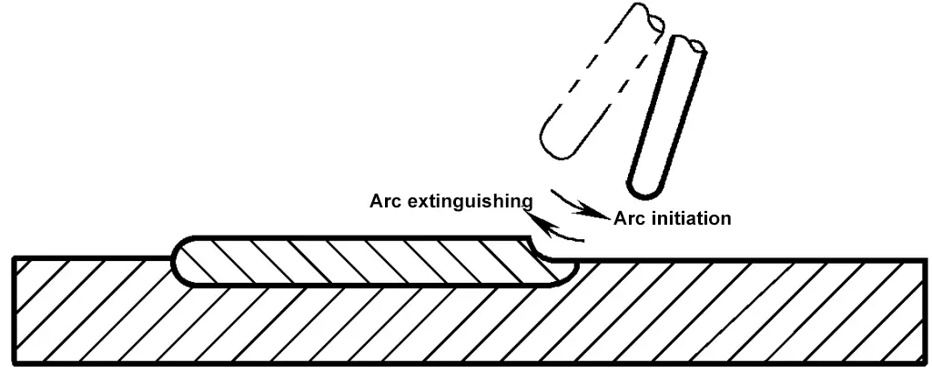
2) Repeated arc-breaking and arc-ending method.
When welding reaches the end of the seam, repeatedly extinguish and reignite the arc several times at the crater until it is filled, as shown in Figure 5-24. This method is suitable for thin plates and high current welding, but not for basic electrodes.
3) Back-welding arc-ending method.
Move the welding arc to the end of the seam, pause briefly, then change the angle of the electrode to back-weld a short section before breaking the arc, effectively making the end a new start, as shown in Figure 5-25. This method is suitable for welding with basic electrodes.
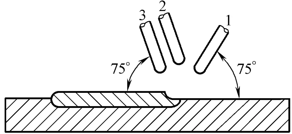
1, 2—Change position appropriately
3—Original position

