Mechanical Assembly: An Essential Guide
The mechanical assembly process is an important part of the mechanical manufacturing process and is also an important chapter that…
The surface quality of machining refers to the surface state of the part after machining. Its main contents include: geometric characteristics of the surface (including surface roughness and surface waviness) and physical and mechanical properties of the surface layer (including work hardening of the surface layer, changes in the metallographic structure of the surface layer, and residual stress in the surface layer, etc.). It is one of the important criteria for evaluating the quality of mechanical parts.
The failure of mechanical parts is mainly due to wear, corrosion, and fatigue of the parts. These damages all start from the surface of the parts, so the surface quality of the parts will directly affect the performance of the parts, especially reliability and lifespan. Therefore, exploring and studying the surface quality of machining and mastering measures to improve surface quality are of great significance for ensuring product quality.
When machining a workpiece with a metal cutting tool, the main reasons for the formation of surface roughness can be summarized into the following three aspects:
Under ideal cutting conditions, when the tool feeds relative to the workpiece, the residual area of the cutting layer left on the machined surface (see Figure 1) forms the theoretical surface roughness. Its value is influenced by the tool nose radius rε , main cutting edge angle kr , secondary cutting edge angle k’r , and feed rate f.
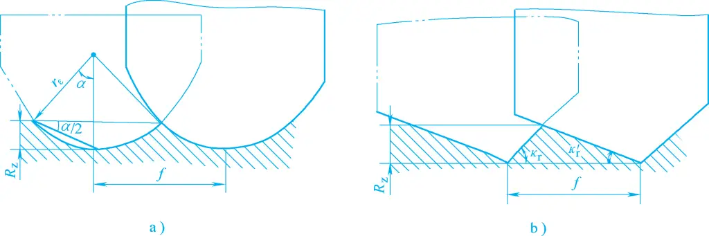
a) The influence of rε and f on Rz
b) The influence of K₂, k’r and f on Rz
The actual surface roughness after cutting is quite different from the theoretical surface roughness. This is because during actual cutting, the cutting force and friction force generated between the tool and the workpiece cause plastic deformation of the surface layer metal, and built-up edge and burrs will increase the surface roughness value.
Such as changes in cutting conditions, vibration of the process system, etc.
1) Select a higher cutting speed v c
The higher the cutting speed, the smaller the plastic deformation of the chips and the machined surface, thus the smaller the surface roughness value. Generally, built-up edge and burrs are generated within a lower speed range, which varies with different workpiece materials, tool materials, and tool rake angles.
Using a higher cutting speed can often prevent the formation of built-up edge and burrs, effectively reducing the surface roughness value. Figure 2 shows the effect of cutting speed on surface roughness when machining different materials.
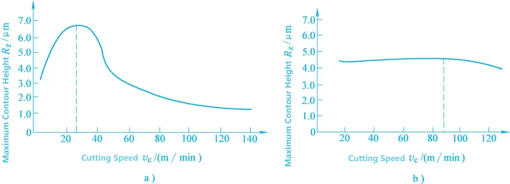
a) Machining plastic materials
b) Machining brittle materials
2) Appropriately reduce the feed rate f
The larger the feed rate, the larger the residual area on the machined surface, and the greater the plastic deformation, which increases the surface roughness value. Therefore, reducing the feed rate will effectively reduce the surface roughness value.
The effect of the depth of cut on surface roughness is not significant and can generally be ignored. However, if the depth of cut is too small, such as α p <0.02mm, it becomes difficult to maintain normal cutting of the workpiece, often resulting in extrusion and friction, thereby increasing the surface roughness value. Therefore, an excessively small depth of cut should not be selected during machining.
The organizational performance of the workpiece material has a significant impact on surface roughness. Generally, the greater the plasticity of the workpiece material, the greater the surface roughness value after machining. When machining brittle materials, the surface roughness value is closer to the theoretical value.
For the same material, the coarser and more uneven the metal grain structure, the greater the surface roughness value after machining. Therefore, adopting a reasonable heat treatment process to improve the organizational performance of the material before machining is one of the effective ways to reduce the surface roughness value.
Tool materials and grinding quality have a significant impact on the formation of built-up edges and scales, thereby affecting surface roughness. For example, diamond tools have a lower friction coefficient with chips and do not produce built-up edges during cutting. Under the same cutting conditions, the surface roughness value after machining is smaller compared to other tool materials.
In addition, reasonably selecting cutting fluids and improving cooling and lubrication effects can often inhibit the formation of built-up edges and scales, reduce plastic deformation, and help reduce surface roughness values. Besides the above-mentioned process measures, machining methods such as grinding, honing, and superfinishing can also achieve very low surface roughness values.
During the machining process, the physical and mechanical properties of the surface layer of the workpiece undergo significant changes under the action of cutting force and cutting heat, mainly reflected in surface layer work hardening, metallographic structure changes, and residual stress.
During machining, the metal on the machined surface layer of the workpiece undergoes plastic deformation under the action of cutting force, causing crystal shear slip, lattice elongation, distortion, and even fragmentation, leading to material strengthening. At this time, its hardness and strength increase, a phenomenon known as work hardening (also called cold work hardening).
On the other hand, the cutting heat generated during machining can, under certain conditions, cause the hardened metal to revert to its original state, i.e., soften. Therefore, the final degree of work hardening of the surface layer depends on the ratio of hardening speed to softening speed.
The factors affecting surface layer work hardening can be analyzed from the following three aspects:
The greater the cutting force, the greater the plastic deformation, and the more severe the work hardening. Therefore, increasing the feed rate f, the depth of cut α p , and reducing the tool rake angle γ o and clearance angle α o will all increase the cutting force, making work hardening more severe.
The higher the cutting temperature, the greater the softening effect, reducing the degree of hardening.
When the cutting speed is very high, the contact time between the tool and the workpiece is very short, and the deformation speed of the cut metal is very fast, resulting in insufficient plastic deformation of the machined surface metal, and thus the resulting work hardening is relatively small.
The above three influencing factors are mainly related to the geometric parameters of the tool, cutting parameters, and the mechanical properties of the material being machined. Therefore, measures to reduce surface work hardening can be considered from the following aspects:
During the cutting process, the temperature of the machined surface will rise due to the cutting heat in the machining area. When the temperature rises above the critical point of metallographic transformation, metallographic changes will occur.
Grinding is a typical machining method that easily causes changes in the surface metallographic structure (grinding burns). This is because the cutting heat generated per unit area during grinding is ten times greater than that of general cutting methods, and about 70% of the heat instantly enters the workpiece, making the metal on the machined surface of the workpiece very easy to reach the phase transformation point.
Factors affecting grinding burns include grinding parameters, workpiece material, grinding wheel performance, and cooling conditions. When grinding quenched steel, if the grinding zone temperature exceeds the martensite transformation temperature but does not exceed its phase transformation critical temperature, the surface martensite transforms into tempered troostite or sorbite with lower hardness, which is called tempering burn.
If the grinding zone temperature exceeds the martensite transformation temperature, martensite transforms into austenite. If there is sufficient cutting fluid at this time, the surface rapidly cools to form secondary quenched martensite, while the lower layer remains a tempered structure with lower hardness due to slower cooling, known as quenching burn. Otherwise, if the cooling conditions are poor or dry grinding is performed without cutting fluid, the surface will be annealed, known as annealing burn.
Regardless of the type of burn, if it is severe, it will significantly reduce the service life of the part, or even render it unusable. Therefore, grinding burns should be avoided during grinding. The root cause of grinding burns is the excessively high temperature in the grinding zone. Therefore, measures should be taken to reduce the generation of grinding heat and accelerate the dissipation of grinding heat to avoid grinding burns. Specific measures are as follows:
Reducing the depth of cut can lower the surface temperature of the workpiece, which helps to avoid or mitigate burns, but it will affect productivity.
Increasing the longitudinal feed rate and workpiece speed will reduce the contact time between the machined surface and the grinding wheel, improving heat dissipation conditions and thus reducing burns. However, this will increase the surface roughness value. To reduce burns while maintaining high productivity and low surface roughness, a higher workpiece speed, smaller depth of cut, and high grinding wheel speed should be selected.
If the grinding wheel hardness is too high, its self-sharpening ability is poor, resulting in high grinding temperatures. The smaller the grain size of the grinding wheel, the easier it is for chips to clog the wheel, making the workpiece more prone to burns. Therefore, it is better to use a coarse-grained and relatively soft grinding wheel. When the grinding wheel becomes dull, most of the abrasive grains only press and rub against the machined surface without cutting, increasing the grinding temperature. Therefore, the grinding wheel should be dressed in a timely manner.
Using cutting fluid can improve cooling effects and avoid burns. However, the commonly used general cooling methods are less effective, as shown in Figure 1. Due to the high linear speed of the grinding wheel, not much cutting fluid can actually enter the grinding zone.
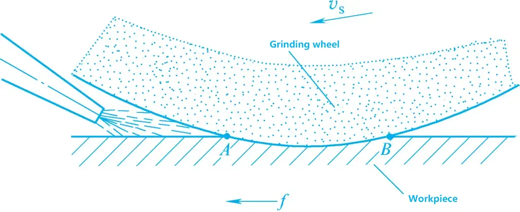
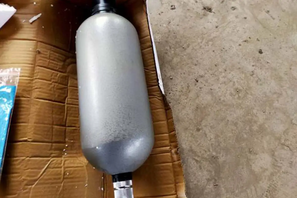
A more effective cooling method is the internal cooling method, as shown in Figure 2. The cutting fluid enters the center cavity of the grinding wheel and is ejected through the wheel pores under centrifugal force, directly entering the grinding zone to provide effective cooling.
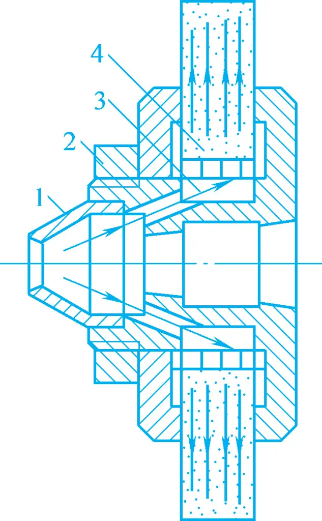
1—Conical cover
2—Cooling fluid through-hole
3—Grinding wheel center cavity
4—Thin-walled sleeve with radial small holes
During cutting and grinding, when the material structure of the machined surface layer changes in shape, volume, or metallographic structure relative to the base material, mutually balanced stresses will be generated at the interface between the machined surface layer and the base material after machining. These are called residual stresses in the surface layer, which can be either compressive or tensile.
The causes of residual stress are as follows:
Under the action of cutting force, the metal in the machined surface layer undergoes intense plastic elongation deformation, while the base metal layer is elastically elongated. After the cutting force is removed, the base metal tends to recover but is restricted by the plastically elongated surface layer metal, preventing it from returning to its original state, thus generating residual compressive stress in the surface layer.
The machined surface of the workpiece undergoes thermal expansion under the action of cutting heat, with the surface layer metal temperature being higher than the base material temperature, generating thermal compressive stress in the surface layer. When the surface layer temperature exceeds the elastic deformation limit of the material, thermal plastic deformation occurs (the material shortens under compressive stress).
After the cutting process ends and the surface temperature drops, the surface layer, having undergone thermal plastic shortening deformation, is restricted by the base material, resulting in residual tensile stress in the surface layer.
The high temperature generated during cutting can cause changes in the metallographic structure of the surface layer metal. Different metallographic structures have different densities, such as martensite density ρ ≈ 7.75g/cm³, austenite density ρ ≈ 7.96g/cm³, and pearlite density ρ ≈ 7.78g/cm³.
Taking the grinding of quenched steel as an example, the original structure of the quenched steel is martensite. After grinding, tempering may occur on the surface layer, transforming martensite into troostite or sorbite, which have densities close to pearlite. The density increases and the volume decreases, resulting in residual tensile stress on the surface layer. If the surface temperature exceeds Ac 3 and cooling is sufficient, the residual austenite in the surface layer transforms into martensite, causing volume expansion and residual compressive stress on the surface layer.
In summary, the generation of residual stress in the surface layer is ultimately due to the effects of cutting force and cutting heat. Under certain processing conditions, one of these effects may dominate. For example, in cutting processing, when the cutting heat is not high, the cold-state plastic deformation caused by the cutting force predominates in the surface layer, resulting in residual compressive stress in the surface layer.
During grinding, due to the generally higher grinding temperature, residual tensile stress is often generated, which is also the root cause of grinding cracks. The presence of cracks on the surface can accelerate the damage of parts. Therefore, it is necessary to strictly control the generation of grinding heat and improve cooling conditions during grinding to avoid the occurrence of grinding cracks.