How to Calculate Sheet Metal Weight: Essential Formulas
Ever wondered how to quickly calculate the weight of sheet metal? This article unveils a simple formula that takes the…
Imagine the perfect cut every time. Laser cutting quality isn’t just about precision; it’s about avoiding defects like overburn and dross. This article dives into the key metrics of cutting surface roughness, kerf width, and kerf taper. Discover how to achieve smooth, defect-free cuts and understand the factors influencing these crucial quality indicators. Learn what makes a laser-cut piece exceptional and how to measure it effectively.

Currently, there are no standards in China regarding the quality of laser cutting surfaces, and there is no unified standard internationally for evaluating the quality of laser cutting. There are many possible indicators for evaluating cutting quality, which can be broadly divided into two categories: One consists of cutting defects, which must be avoided during the cutting process.
If these defects are present, the cut product is deemed unacceptable. The other category includes quantifiable cutting quality indicators, which vary depending on the specific product being cut.
Overburn occurs when the laser power is too high or the cutting speed too slow, causing the melting range of the workpiece to exceed the scope that the high-pressure gas flow can blow away. The molten metal is not completely blown away, resulting in overburn and an irregularly shaped cutting surface, as shown in Figure 8-2.
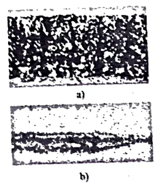
a) Profile of overburn cutting surface
b) Top view of the kerf
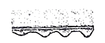
Dross refers to the phenomenon when the auxiliary gas flow fails to completely blow away the melted or vaporized material produced during cutting, resulting in slag adhering to the lower edge of the cutting surface, as shown in Figure 8-3. Strictly speaking, if what adheres to the lower edge is not entirely or partially slag but solidified metal, it should be referred to as nodules.
For simplicity’s sake, this document collectively refers to these as dross, all of which are considered a type of cutting defect.
The roughness of the cutting surface, denoted as Rz, is an important indicator of cutting quality. If a cutting surface profile is as shown in Figure 8-4a, the surface contour line at line AB in Figure 8-4a measured by a surface roughness meter is as shown in Figure 8-4b.
Rz is the average distance from the five highest points to the five lowest points on the contour line within the sampling length, representing the roughness of the cutting surface at line AB. This chapter will mainly analyze the process factors affecting roughness and the real-time detection and control of roughness.
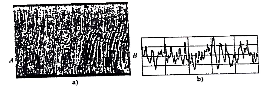
a) Profile of the cutting surface
b) Surface contour line at position AB
The kerf width mainly depends on the beam mode and the diameter of the focused spot; cutting parameters also have some impact.
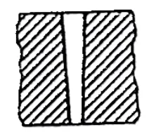
When the cutting parameters are improperly selected or the auxiliary gas pressure is insufficient, the kerf tends to be wider at the top and narrower at the bottom, showing a taper, as shown in Figure 8-5. However, this is not a significant issue for thin plate cutting.
In summary, the main indicators of high-quality laser cutting are defect-free cuts, low surface roughness values, and narrow kerf widths.
For laser cutting of materials thicker than 2mm, the distribution of cutting surface roughness is uneven and varies greatly along the thickness direction, with two prominent characteristics:
1) The cutting surface profile is divided into two distinct parts, as shown in Figure 8-6. The upper part is smooth and the cutting stripes are neat and dense, resulting in a smaller roughness value. The lower part has disordered cutting stripes and an uneven surface, resulting in a larger roughness value. The upper part has the characteristics of direct laser beam action, while the lower part has the characteristics of molten metal scouring.
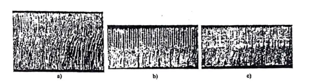
a) Continuous laser cutting, plate thickness 3mm, P=800W, v=30mm/s
b) Pulsed laser cutting, plate thickness 2mm, P=600W, f=150Hz, v=15mm/s
c) Pulsed laser cutting, plate thickness 2mm, P=600W, f=250Hz, v=15mm/s
2) The surface roughness in the upper area of the cutting surface is generally uniform and does not change with height, whereas the surface roughness in the lower area varies with height, increasing towards the lower edge. The maximum surface roughness value is reached at the bottom edge, as shown in Figure 8-7.
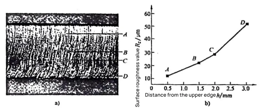
a) Profile of the cutting surface
b) Surface roughness value variation curve with height
Note: Plate thickness 3mm, P=800W, v=40mm/s.
From the above, it can be seen that the position near the lower edge, D, is where the surface roughness value is maximum, representing the weak link in the cutting surface quality. Therefore, when evaluating cutting surface quality, the roughness of the lower edge should be used as the benchmark. However, the true lower edge is just a line and its roughness is difficult to measure.
To address this, the roughness near the lower edge can be measured as a substitute. In this chapter, it is referred to as “near-edge roughness”. Unless otherwise noted, all evaluations, detections, and controls of cutting quality in this chapter are based on near-edge roughness.
Most of the literature published domestically and internationally, including the references cited in this chapter, uses the roughness at 1/3 from the bottom edge of the workpiece thickness as the benchmark.
While this is useful for describing trends in cutting surface quality or for comparisons, it is not suitable as a basis for acceptance or control, as it is not the maximum surface roughness value and does not truly represent the quality of the cutting surface that has practical application value.