I. Basic Process Knowledge
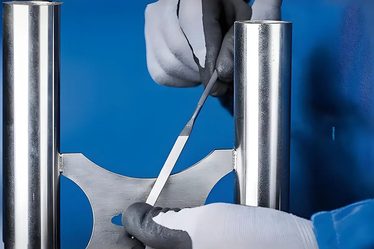
Filing is a machining method that uses a file to remove a layer of metal from the surface of a workpiece to meet the technical requirements of the drawing. Filing can achieve dimensional tolerance grades of IT8 to IT7 and surface roughness Ra of 1.6 to 0.8μm, therefore, it has relatively wide applications in practical work.
Filing operations can be used to process various internal and external surfaces, curved surfaces, and special shapes; it is commonly used in the manufacture of templates, molds, and machine assembly, adjustment, and maintenance.
1. Structure of a File
As shown in Figure 1, a file consists of the file face, file edge, file tang, file teeth, and file handle.

1—File Face
2—File Edge
3—File Teeth
4—File Handle
5—File Tang
(1) File Face
The file face is the main working surface of the file. It is slightly convex in the longitudinal direction to prevent concave deformation after heat treatment and to counteract the convex phenomenon produced on the workpiece due to the up and down swinging of the file during filing, ensuring that the workpiece can be filed flat.
(2) File Edge
The file edge refers to the two side faces of the file. One edge has teeth, while the other does not. The edge without teeth is called the safe edge or smooth edge.
(3) File Tang
The file tang refers to the tail end of the file, used for insertion into the file handle, making it easy to grip and transmit thrust during filing.
(4) File Teeth
File teeth are usually cut on a file-cutting machine, and their shape and filing principle are shown in Figure 2. During the filing process, chips are cut off from the workpiece through pressure on the workpiece and friction generated with the workpiece.
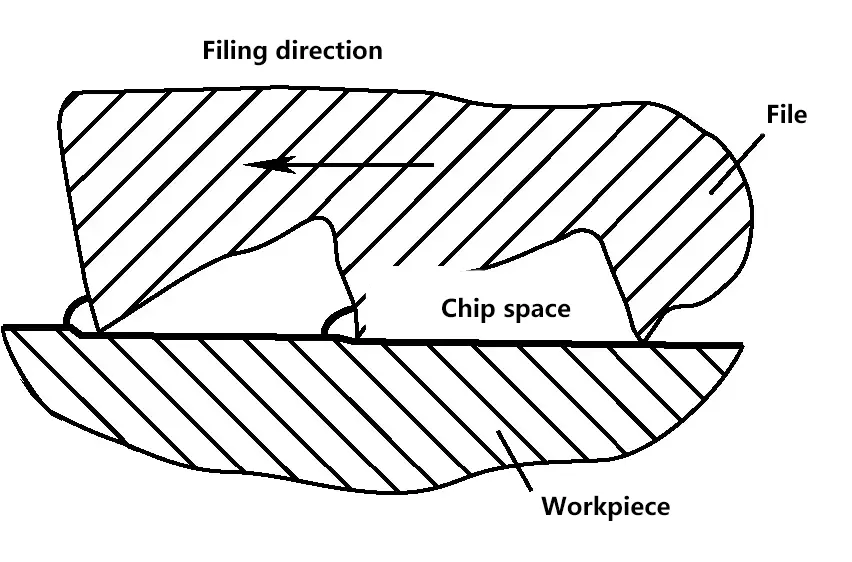
The file’s tooth pattern is often made into a double pattern. When filing, the file marks of each tooth intersect without overlapping, resulting in a smoother filed surface. The chips are broken during filing, making it less labor-intensive. The filings are less likely to clog, and the file teeth have higher strength, suitable for filing hard materials.
2. Types and Specifications of Files
(1) Types of Files
Files used by fitters can be divided into three categories according to their uses: general files, shaping files, and special-shaped files.
General files are divided into five types based on their cross-sectional shapes: flat files, square files, triangular files, half-round files, and round files. Among these, flat files are the most commonly used, as shown in Figure 3.

Special-shaped files are used for filing special surfaces of workpieces and include knife-edge files, diamond files, flat triangular files, oval files, and barrel files, as shown in Figure 4.

As shown in Figure 5, shaping files, also known as needle files or assorted files, are named for their grouped sets of small files with various cross-sectional shapes, mainly used for finishing small parts of workpieces.

(2) File Specifications
File specifications are divided into size specifications and tooth pattern coarseness specifications.
1) Size Specifications
Different file size specifications are represented by different parameters. Round files are specified by diameter; square files are specified by square dimensions; other files are specified by the length of the file body. Fitters commonly use files in sizes of 100mm, 125mm, 150mm, 200mm, 250mm, 300mm, 350mm, and 400mm.
2) Coarseness Specifications
Coarseness specifications are usually represented by the number of main file grooves per 10mm of axial length, divided into five grades.
Grade 1 tooth pattern is for coarse-toothed files; Grade 2 for medium-toothed files; Grade 3 for fine-toothed files; Grade 4 for double fine-toothed files; Grade 5 for superfine files.
3. File Selection
Before filing, it is necessary to select the correct file. Each type of file has a specific use, and if chosen incorrectly, it cannot fully demonstrate its effectiveness and may even prematurely lose its cutting ability. File selection mainly involves choosing the cross-sectional shape and the coarseness specification of the file.
(1) Selection of File Cross-sectional Shape
The cross-sectional shape and length of the file should be selected based on the shape and size of the surface to be filed on the workpiece. The file shape should adapt to the shape of the workpiece surface to be processed, as shown in Figure 6.
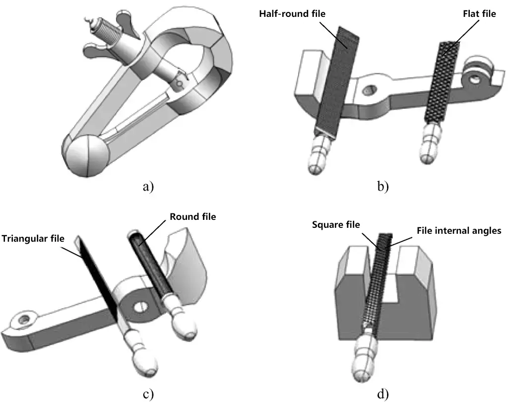
a) Hand Vice
b) Application of Flat File and Half-round File
c) Usage of Round File and Triangular File
d) Usage of Square File
(2) Selection of File Coarseness Specification
The selection of file coarseness specification depends on the nature of the workpiece material, the size of the machining allowance, and the requirements for processing accuracy and surface roughness. Coarse files, with larger tooth spacing that is less prone to clogging, are generally used for filing soft metals such as copper and aluminum, and for workpieces with large machining allowances, low precision requirements, and rough surface finishes. Fine files are used for filing steel, cast iron, and workpieces with small machining allowances, high precision requirements, and low surface roughness values. Superfine files are used for the final polishing of workpiece surfaces.
Table 1 provides reference information on the suitable machining allowances and achievable processing accuracy and surface roughness for files of various coarseness specifications, to assist in selecting the appropriate file coarseness specification.
Table 1 Selection of file coarseness specifications
| File cut number | File teeth | Applicable situations | |||
| Processing allowance/mm | Dimensional accuracy/mm | Roughness Ra/μm | Application | ||
| 1 | Coarse | 0.5~1 | 0.2~0.5 | 100~25 | Suitable for rough machining or non-ferrous metals |
| 2 | Medium | 0.2~0.5 | 0.05~0.2 | 25~6.3 | Suitable for processing after rough filing |
| 3 | Fine | 0.1~0.3 | 0.02~0.05 | 12.5~3.2 | Polishing surfaces or hard metals |
| 4 | Double fine | 0.1~0.2 | 0.01~0.02 | 6.3~1.6 | Fine machining |
| 5 | Oil finish | Below 0.1 | 0.01 | 1.6~0.8 | Surface finishing |
4. Flat filing methods and curved surface filing methods
(1) Flat filing methods
1) Straight filing method
As shown in Figure 7a, the straight filing method is a way of filing the workpiece in the same direction. It is the basic method of filing, characterized by straight and neat file marks, which can reduce the surface roughness value.
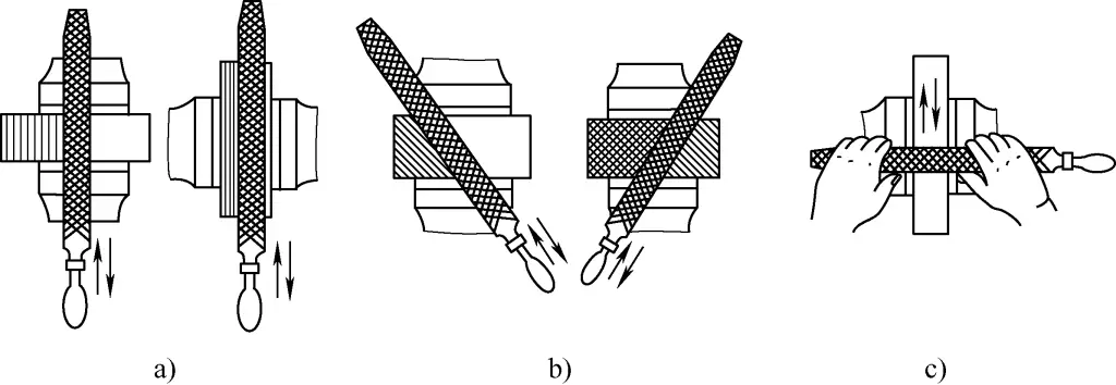
a) Straight filing method
b) Cross filing method
c) Push filing method
2) Cross filing method
As shown in Figure 7b, the cross filing method is filing the workpiece from two directions crosswise. Its characteristic is that it can show uneven traces on the filed surface, making it easier to file off the high spots. This method makes it easier to file an accurate flat surface.
3) Push filing method
As shown in Figure 7c, the push filing method involves holding the file body horizontally with both hands and steadily pushing it back and forth along the workpiece surface. Its characteristic is less cutting volume, reducing the surface roughness value, and is generally used for filing narrow and long surfaces.
During the filing process, it should be noted that regardless of the filing method, filing should be done evenly across the entire processing surface.
(2) Curved surface filing methods
Arc surface filing includes two types: outer arc surface filing and inner arc surface filing. Flat files are used for outer arc surfaces, while half-round files or round files are used for inner arc surfaces.
1) Outer arc surface filing
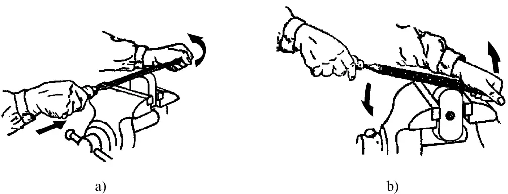
The file needs to complete two movements: forward movement and rotation of the file around the workpiece. There are two filing methods for outer arc surfaces:
① Segmented arc surface filing
Place the file horizontally against the arc surface, file off the edges in sequence to create a basic polygon approximating the arc, and finally use the straight filing method to file it into an arc, as shown in Figure 8a. This method is efficient and suitable for rough machining stages.
a) Segmented arc surface filing
b) Straight arc surface filing
② Straight arc surface filing
When filing, while pushing the file forward, press down on the file handle with the right hand and lift the file tip with the left hand, as shown in Figure 8b. This ensures that the filed arc surface has no edges and is smooth, suitable for the fine machining stage of arc surfaces.
2) Inner arc surface filing
As shown in Figure 9, the file needs to complete three movements simultaneously: forward movement; moving left or right (about half to one file width); and rotating around the file’s centerline (clockwise or counterclockwise about 90°).
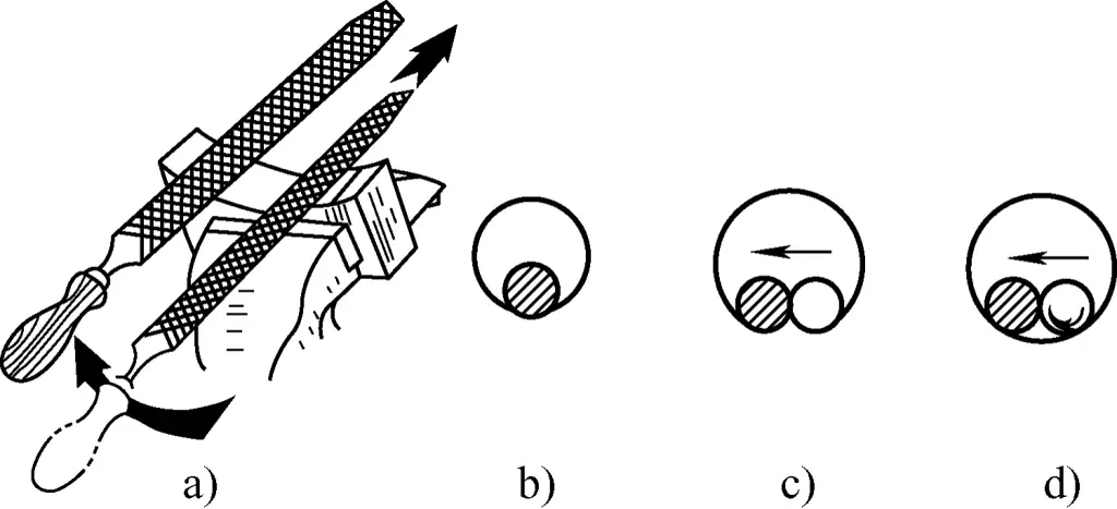
If there is only forward movement, the circular hole will not be round; if there is only forward movement and left or right movement, the arc surface shape will also be incorrect. Only by completing all three movements simultaneously can the inner arc surface be filed well, as this allows the file’s working surface to slide and file along the workpiece’s arc in an arc shape.
5. Filing quality inspection methods
(1) Flatness inspection method
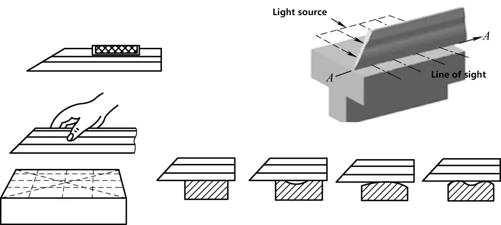
After flat filing, a knife-edge straightedge or steel ruler is often used with the light gap method to check its flatness. If the light passing through between the ruler and the workpiece surface is weak and uniform, it indicates that the surface is flat; if the light passing through is uneven in strength, it indicates that the surface is not level, with the strongest light area being the most concave part. Flatness should be checked in longitudinal, transverse, and diagonal directions, as shown in Figure 10.
(2) Perpendicularity inspection method
As shown in Figure 11, when using a try square to check the perpendicularity of the machined surface to the reference surface, the short edge of the try square should be gently pressed against the reference surface of the workpiece, with the long edge against the surface being checked. Use the light gap method to inspect, with requirements similar to checking flatness.

a) Correct measurement method
b) Incorrect measurement method
(3) Parallelism inspection method
There are several methods for checking parallelism during filing, but two methods are commonly used:
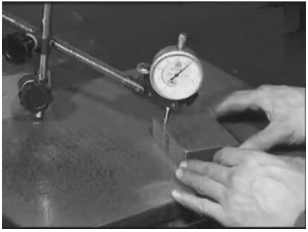
1) Using a dial indicator to check the parallelism of the machined surface. As shown in Figure 12, place the reference surface of the workpiece on a standard surface plate, move the workpiece, and read the maximum and minimum values from the dial indicator. The difference between the two is the parallelism error of the measured surface.
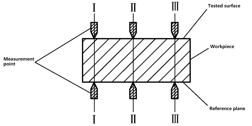
2) Using a vernier caliper or micrometer to measure parallelism. As shown in Figure 13, measurements should be taken at several positions to find the highest point (maximum value) and the lowest point (minimum value). The difference between the two is the parallelism error of the measured surface.
(4) Profile inspection method
As shown in Figure 14, when processing a bench vise, a radius gauge can be used to check the inner arc surface.

6. Filing safety precautions
- Do not use files without handles or with cracked handles for filing.
- Use a brush to remove file chips; blowing with the mouth is prohibited to prevent chips from flying into the eyes.
- Do not touch the file surface or the workpiece surface after filing with your hands to prevent slipping during refiling, which could cause accidents.
- Files should not be used as hammers or pry bars.
II. Basic operational skills
1. Installing and removing file handles
(1) Installing file handles
First, select an appropriate file handle based on the size of the file. Generally, large file handles are used for files 250mm and above, medium file handles for files between 150mm and 250mm, and small file handles for files below 150mm.
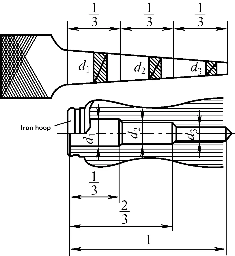
As shown in Figure 15, before installing the file handle, drill a hole in the handle. The shape and size of the stepped hole should match the file tang.
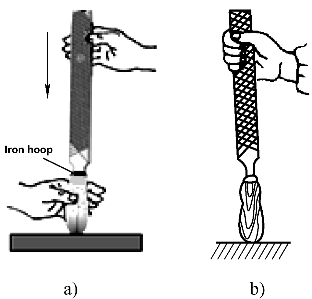
The process of installing the file handle is shown in Figure 16. Hold the handle with your left hand, insert the file tang into the handle hole with your right hand, and gently tap it in. Release your left hand, then use your right hand to tap the file vertically until it’s firmly seated, with the inserted length about 3/4 of the file tang.
a) Insertion
b) Tapping in
(2) Removing file handles
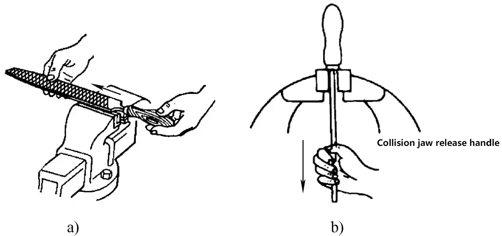
As shown in Figure 17, when removing a file handle on a bench vise, place the hole end of the file handle on the vise jaw and strike it lightly against the jaw. The inertia will separate the file from the handle. This method can also be used on a vise table.
a) File handle removal method one
b) File handle removal method two
2. Key points of filing operation
(1) Workpiece clamping during filing
When filing, the workpiece is generally clamped in the middle of the bench vise, with the exposed part above the vise jaw not too high to prevent workpiece vibration during filing, which can cause chatter marks. The workpiece should be clamped appropriately tight; if too loose, the position of the filed surface may change during filing, affecting surface quality; if too tight, some open parts may deform. When using a previously machined surface as the clamping surface, use vise jaw covers to avoid damaging the machined surface.
(2) File gripping method
Only by correctly gripping the file with both hands and coordinating them can one effectively control the horizontal movement of the file and effectively apply filing force to the surface being filed.
1) Right-hand file gripping method
Except for shaping files, the right-hand grip method for other files is basically the same, as shown in Figure 18.
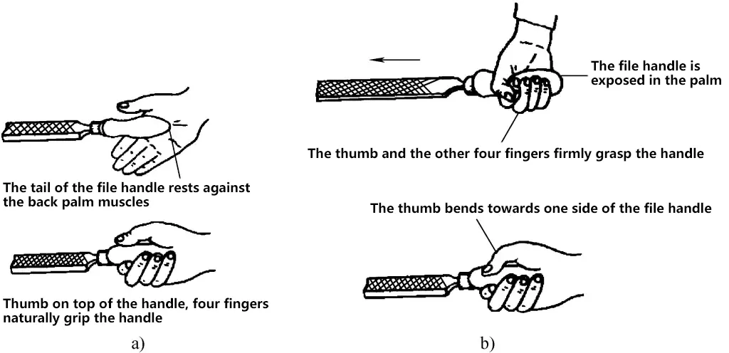
a) Correct right-hand file grip method
b) Incorrect file grip method
2) Left-hand file grip method
The correct method for gripping the file with the left hand is shown in Figure 19, where the grip method shown in Figure 19a is typically used for holding large flat files.
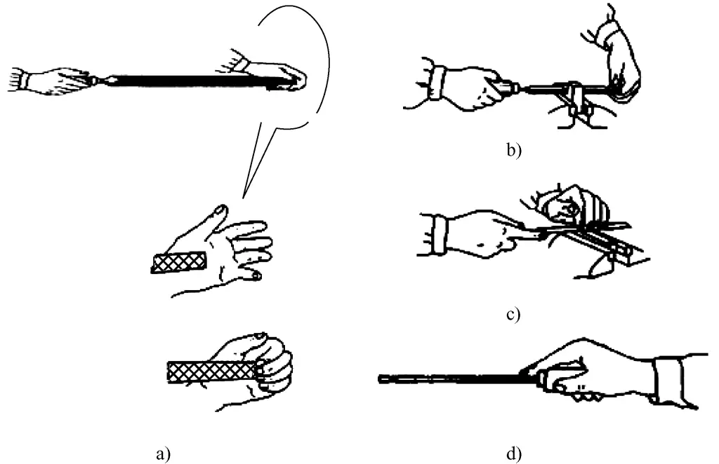
a) Basic file grip method
b) Grip method for medium-sized files
c) Grip method for small files
d) Grip method for shaping files
(3) Standing posture
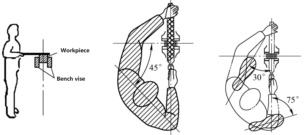
As shown in Figure 20, stand with both feet facing the bench vise, positioned to the left of the vise’s centerline. The body should form a 45° angle with the vise jaw edge. The distance from the vise is determined by keeping the upper and lower arms vertical, the file level, and the file tip able to rest on the workpiece.
Step out with the left foot, with the distance (from right toe to left heel) approximately equal to the file length. The left foot should form about a 30° angle with the vise centerline, and the right foot about a 75° angle.
(4) Body movements
1) As shown in Figure 21a, throughout the filing process, keep the right wrist slightly arched and the right shoulder lowered (right shoulder slightly lower than the left), known as “sinking the shoulder and dropping the hand”. This posture facilitates pushing the file horizontally. The incorrect posture is shown in Figure 21b.
Without affecting the movement of the right arm, keep the right arm as close to the body as possible (maintaining about a fist’s distance between the right upper arm and the body). This allows the upper body strength to be easily applied to the file during filing.
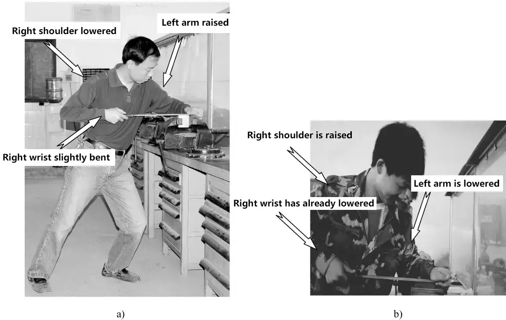
a) Correct body movements during filing
b) Incorrect body movements during filing
2) As shown in Figure 21a, throughout the filing process, the left arm should always be raised to apply pressure to the filing surface. The incorrect posture is shown in Figure 21b.
3) As shown in Figure 21a, maintain balance during filing, with the center of gravity on the left foot. Keep the right knee straight and both feet firmly planted. Use the flexing and extending of the left knee for reciprocating motion.
4) Continuous filing process. The continuous filing process is shown in Figure 22.

① The filing motion is a combination of body and arm movements. At the start of filing, lean the body forward about 10°, with the right elbow pulled back as far as possible.
② When the file has advanced one-third of the way, lean the body forward to about 15°, with the left knee slightly bent.
③ When the file has advanced another third, gradually lean the body to about 18°.
④ When the file has completed 2/3 of its full stroke, continue pushing forward to complete the full filing stroke (Note: The file handle should not touch the edge of the workpiece). Use the reaction force from pushing the file forward to return the body to a 10° lean position in the opposite direction of the forward push (Note: Keep both feet firmly planted when the body returns, without lifting or moving feet). Prepare for the second forward filing motion.
⑤ When returning the file, lift it slightly (no pressure is applied during the return stroke) and move it slightly to the side to judge the flatness of the surface from the file marks.
⑥ Throughout the filing process, the forward stroke of the file should be no less than 2/3 of the file’s full length, with a filing frequency of about 30-40 times/min.
(5) Application of filing force
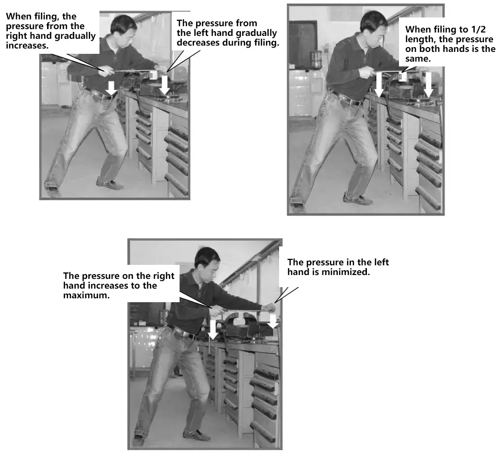
The key to ensuring a flat filing surface is balancing the filing force moment, i.e., maintaining a horizontal linear motion of the file during the forward stroke. Therefore, when pushing the file, the force applied by both hands should continuously change as the file advances. The left hand pressure should decrease from large to small, while the right hand pressure increases from small to large, ensuring that the force moments from both hands are equal relative to the workpiece center, as shown in Figure 23.
3. Filing process for individual parts
(1) Analyzing the part drawing
Through analysis of the part drawing, the following processing information should be understood:
1) The position and number of reference points.
2) The dimensional tolerances, geometric tolerances, and surface roughness requirements for the surfaces to be filed on the part.
(2) Inspecting the workpiece
Check the workpiece according to the information on the part drawing:
1) Check if the workpiece material matches the technical requirements on the part drawing.
2) Check for workpiece defects.
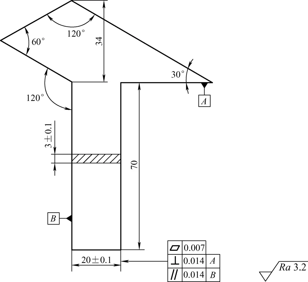
① Use a steel ruler or scribing block to check for bending, twisting, or warping of the workpiece, as well as flatness errors; use a try square to preliminarily check its perpendicularity and determine if it meets processing conditions (whether geometric tolerances can be guaranteed after processing).
As shown in Figure 24, for a thin plate right angle part, check the bending, twisting, or warping of the thin plate material before processing. Minor deformations can be corrected; if severely deformed, the workpiece should be replaced.
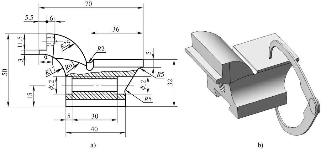
② Use calipers in combination with a steel ruler to measure the workpiece, especially local concave defects, to determine if the minimum size is larger than the dimensions marked on the part drawing, and assess the machining allowance. If the minimum size of the workpiece is smaller than the marked dimension, or if the machining allowance is too small to guarantee the dimensional and geometric tolerances after processing, it should be considered a defective workpiece.
Figure 25 shows the processing diagram for the movable jaw of a bench vise. Before processing, use calipers and steel rulers to check various dimensions and assess the machining allowance. Figure 25b shows the measurement of the height (32mm) between the platform and the base.
(3) Determining the processing plan
1) Determine the marking method.
2) Determine the filing processing sequence.
① For a single part, usually start by finishing the reference surface to ensure its geometric accuracy.
② For a single part, typically first ensure the perpendicularity of the processed surface to the reference, then its parallelism and dimensions, and finally refine its flatness. After fine finishing, ensure that the dimensional tolerances, geometric tolerances, and surface roughness all meet the requirements marked on the part drawing.
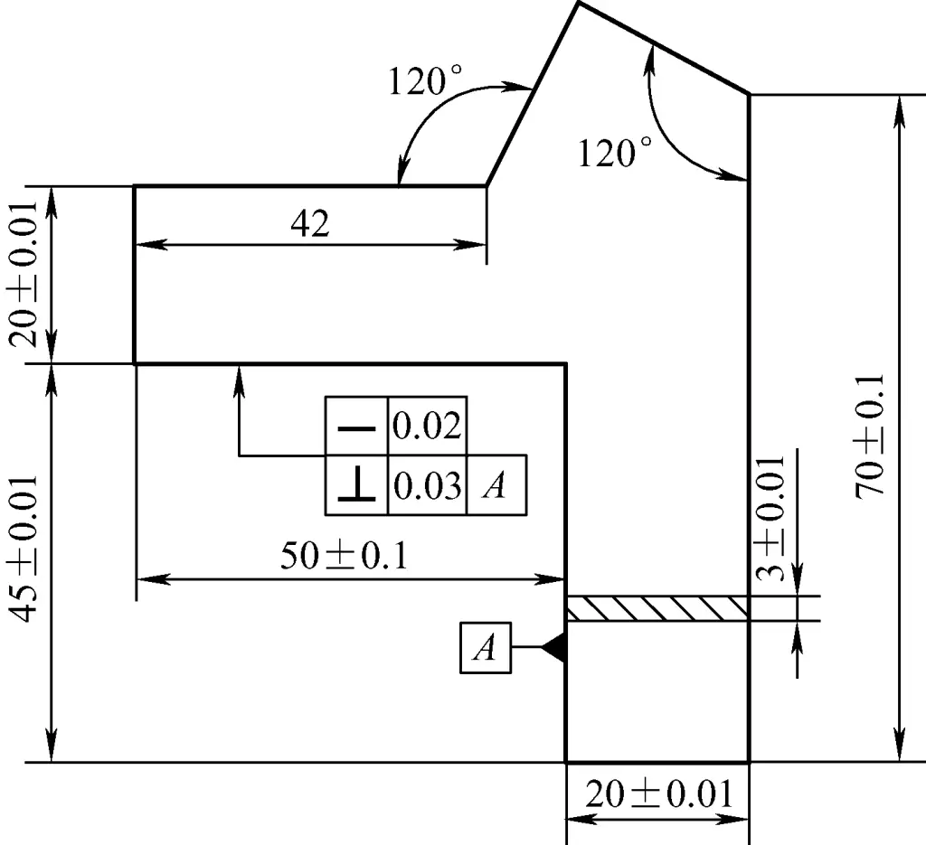
③ To prevent workpiece deformation during processing, consider processing internal shapes first, then external contours, especially for thin plate materials.
Figure 26 shows an angle measurement template made from 3mm thin plate material. To prevent workpiece deformation, process the inner right angle and inner 120° angle first, then process the outer 120° angle.
3) Determine the machining allowance. Usually, filed surfaces go through rough filing and fine filing (including fine finishing) processes, so reasonably allocating machining allowance can lead to more efficient processing results.
4) Determine the method for removing material. For workpieces with internal slots, the process of removing internal solid material is called material removal. As shown in Figure 27, the method of drilling holes followed by chiseling or sawing is commonly used for material removal (see drilling methods for details).
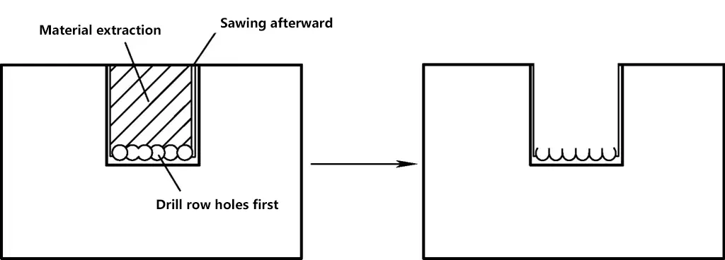
5) During the processing, pay attention to proper workpiece clamping methods to prevent deformation.
(4) Measurement issues during processing
During processing, ensuring dimensional accuracy and geometric accuracy of the part is crucial, and striving for measurement accuracy is a vital step. Based on the process of obtaining measurement results, measurements can be divided into direct measurement and indirect measurement.
1) Direct measurement
Any measurement that can directly and accurately obtain the part’s dimensions and geometric errors using measuring tools is called direct measurement. This includes external dimensions and geometric errors of parts. Direct measurements are relatively easy to obtain accurate results and are simpler, so they won’t be discussed further here.
2) Indirect measurement
Any measurement that cannot be directly measured with tools, or can be directly measured but cannot obtain accurate results directly, is called indirect measurement.
As shown in the workpiece in Figure 28, the depth dimension of 15+0.050 mm is difficult to measure accurately using a vernier caliper. Therefore, the dimension chain method can be used to calculate the upper and lower deviation values of dimension L. During filing, control dimension L and the 250+0.05 mm dimension to control the 15+0.050 mm dimension.
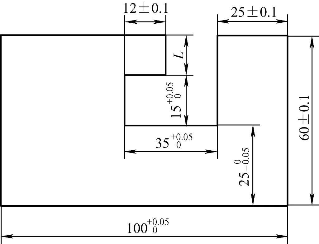
Figure 29 shows a simplified diagram of this dimension chain. The solution process is as follows:

Dimension L is the closing link formed after all other dimensions are determined. Following the arrows, (60±0.1) mm is an increasing link, while 250-0.05 mm and 15+0.050 mm are decreasing links. Thus, we have:
- Lmax=(60.1-24.95-15) mm =20.15mm
- Lmin=(59.9-25-15.05) mm =19.85mm
Therefore, during filing, measure dimension L and the 25mm dimension, and control the filing dimension range to 250-0.05 mm and (20±0.15) mm to ensure the filing accuracy requirement of 15+0.050 mm.

