I. Characteristics of Fitting Craftsmanship
Fitting refers to the trade that uses various hand tools and some mechanical equipment to complete the processing of certain parts, the assembly and debugging of components and machines, as well as the maintenance and repair of various mechanical equipment. The characteristics of fitting are that the direction of tool movement is not restricted, and it features simple tool usage, flexible, diverse, and convenient operation, and wide adaptability. Therefore, it can accomplish tasks in mechanical processing that are difficult to complete.
Fitting is a trade with relatively complex technical processes, detailed processing procedures, and high craftsmanship requirements. Although there are many advanced processing methods available today, many tasks still require fitting to complete. Fitting plays an important role in ensuring product quality. The main operating methods of fitting include marking, chiseling, sawing, filing, scraping, drilling, reaming, boring, tapping, and threading.
II. Marking
The essence of plane marking is a problem of plane geometry drawing. Plane marking involves using marking tools to draw the pattern onto the workpiece blank at a 1:1 scale according to the actual size. The steps for plane marking are as follows:
- Select the marking reference according to the drawing requirements.
- Prepare the workpiece before marking (cleaning, inspection, coloring, installing center plugs in the holes of the parts, etc.). Apply a thin and even layer of coating (i.e., coloring) to the marking area on the workpiece to make the drawn lines clearly visible. Different workpieces require different coatings. Generally, lime water is applied to cast and forged blanks, chalk can be used on small blanks, gentian violet (also known as “blue oil”) or copper sulfate solution is applied to steel semi-finished products, and gentian violet or ink is applied to aluminum, copper, and other non-ferrous metal semi-finished products.
- Draw the machining boundary lines (straight lines, circles, and connecting arcs).
- Punch sample holes along the drawn lines.
III. Sawing
The method of cutting materials with a handsaw or sawing grooves on a workpiece is called sawing.
1. Composition of the handsaw
The handsaw consists of a saw bow and a saw blade.
(1) Saw bow
There are two types of saw bows: fixed and adjustable, as shown in Figure 1.

(2) Saw blade
Saw blades are generally made of carbon tool steel and are quenched and tempered at low temperatures. According to the pitch of the saw teeth, saw blades can be divided into coarse-tooth, medium-tooth, and fine-tooth saw blades. Coarse-tooth saw blades are suitable for sawing soft materials and large cross-section parts, while fine-tooth saw blades are suitable for sawing hard materials and thin-walled parts.
2. Sawing methods
(1) Installation of the saw blade
When sawing, the saw cuts when pushed forward, so the saw teeth should face forward when installing the saw blade. The saw blade should not be too tight or too loose; too tight can cause the saw blade to break, and too loose can cause the saw cut to skew. Generally, the adjustment nut should be tightened with the strength of two fingers.
(2) Installation of the workpiece
The workpiece should not extend too far from the vise jaws to avoid vibration during sawing. The saw line should be parallel to the edge of the vise jaws and clamped on the left side of the vise for easy operation. The workpiece should be clamped tightly but not deformed or damaged on the machined surface.
(3) Holding the handsaw
Generally, hold the saw handle with the right hand and lightly support the front end of the saw bow with the left hand.
(4) Starting the saw
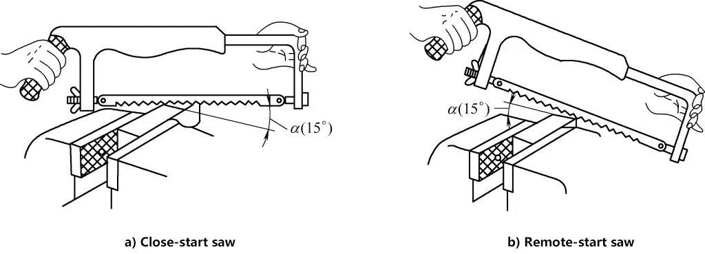
When starting the saw, the saw blade should be slightly inclined at an angle α (10°-15°) to the workpiece surface, not too large to prevent tooth breakage. To prevent the saw blade from sliding sideways, you can press the thumb against one side of the saw blade. When starting the saw, quickly push and pull the saw back and forth. Once a small saw cut is made, remove the left hand from the saw blade and lightly press the front end of the saw bow to continue sawing.
(5) Sawing
During sawing, the saw bow should move back and forth in a straight line without swaying to prevent the saw blade from breaking. When pushing the saw forward, apply even pressure with both hands for cutting; when returning, let the saw blade lightly slide over the machined surface without applying pressure.
The back-and-forth motion during sawing should not be too fast, about 30-40 times per minute. Ensure that 2/3 of the saw blade length is involved in the sawing work to prevent local wear and damage. During sawing, lubricants should be added for lubrication and cooling, such as machine oil for steel parts and water for aluminum parts.
3. Key points of sawing operation
(1) Holding the saw and sawing operation
The general method of holding the saw is to hold the saw handle firmly with the right hand and lightly support the front end of the saw bow with the left hand. The standing position during sawing is shown in Figure 2. The pushing and pressing forces during sawing are controlled by the right hand, while the left hand should not apply too much pressure and should mainly assist the right hand in keeping the saw bow straight. Apply pressure when pushing the saw forward and release pressure when returning, letting the saw blade lightly slide over the workpiece. The speed of the back-and-forth motion during sawing should be controlled at about 30 times per minute.
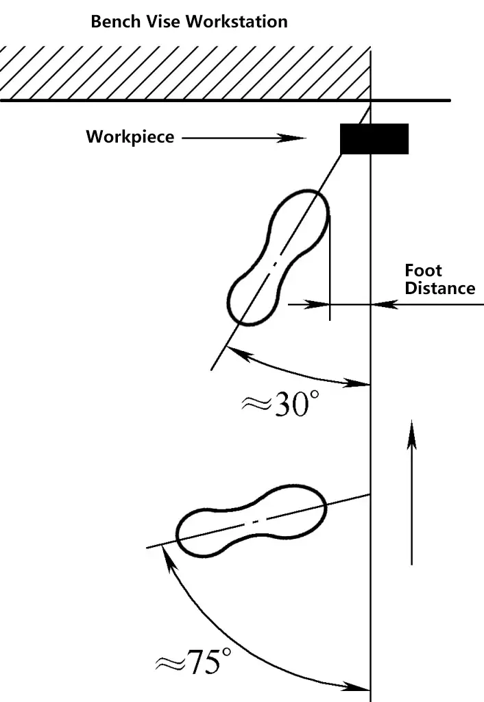
(2) Starting the saw: The process of the saw blade beginning to cut into the workpiece is called starting the saw.
There are two methods of starting the saw: near starting (Figure 3a) and far starting (Figure 3b). When starting the saw, use the left thumb nail to block the saw blade, with a starting angle of about 15°. The saw bow should have a short stroke and light pressure. The saw blade should be perpendicular to the workpiece surface. When the starting cut reaches a depth of 2-3mm, the starting process can end, and the saw bow should gradually be adjusted to a horizontal position for normal sawing.
IV. Filing
The operation of using a file to remove excess metal from the surface of a workpiece to achieve the required dimensions, shape, and surface roughness as per the drawing is called filing. Filing can process the internal and external surfaces, grooves, curved surfaces, and various complex surfaces of parts. The scope of filing includes planes, stepped surfaces, angled surfaces, curved surfaces, grooves, and various shaped holes.
1. Types of Files
A file consists of a file face, file edge, and file handle (with a handle attached), as shown in Figure 4. The specifications of a fitter’s file are indicated by the length of the working part and are divided into seven types: 100mm, 150mm, 200mm, 250mm, 300mm, 350mm, and 400mm. Depending on the size, files are further divided into fitter’s files and shaping files.

Fitter’s files include flat files, half-round files, square files, triangular files, and round files, with flat files being the most commonly used. Shaping files are smaller in size and usually come in a set of 10 files of various shapes, used for filing small workpieces and parts that are difficult to machine. Files are made of carbon tool steel T12, T13, T12A, and T13A, and are hardened after heat treatment, with a hardness of 62~67HRC.
(1) Files are classified into single-cut files and double-cut files based on the tooth pattern. Single-cut files have teeth in only one direction, forming a 70° angle with the file’s centerline, and are generally used for filing soft metals such as copper, tin, and lead. Double-cut files have teeth arranged in two intersecting directions; the first cut is called the bottom cut, and the second cut is called the top cut.
The bottom cut forms a 45° angle with the file’s centerline and has a wider tooth spacing; the top cut forms a 65° angle with the file’s centerline and has a narrower tooth spacing. Due to the different angles and spacings of the bottom and top cuts, the filing marks do not overlap, resulting in a smooth and flat surface.
(2) Files are classified by cross-sectional shape into flat files (for filing planes, external cylindrical surfaces, and convex arcs), square files (for filing planes and square holes), triangular files (for filing planes, square holes, and angles greater than 60°), round files (for filing round and internal arc surfaces), and half-round files (for filing planes, internal arc surfaces, and large round holes), as shown in Figure 5a. Figure 5b shows special files used for processing special surfaces of various parts.

(3) Files are classified by the number of teeth per 10mm length into:
- Coarse-tooth files: 4 to 12 teeth per 10mm length, with large tooth spacing, not easily clogged, suitable for rough machining or filing non-ferrous metals such as copper and aluminum.
- Medium-tooth files: 13 to 23 teeth per 10mm length, with moderate tooth spacing, suitable for processing after rough filing.
- Fine-tooth files: 30 to 40 teeth per 10mm length, suitable for filing smooth surfaces or hard metals.
- Dead-smooth files: 50 to 62 teeth per 10mm length, suitable for fine finishing to smooth surfaces.
2. Filing Steps
(1) File Holding Method
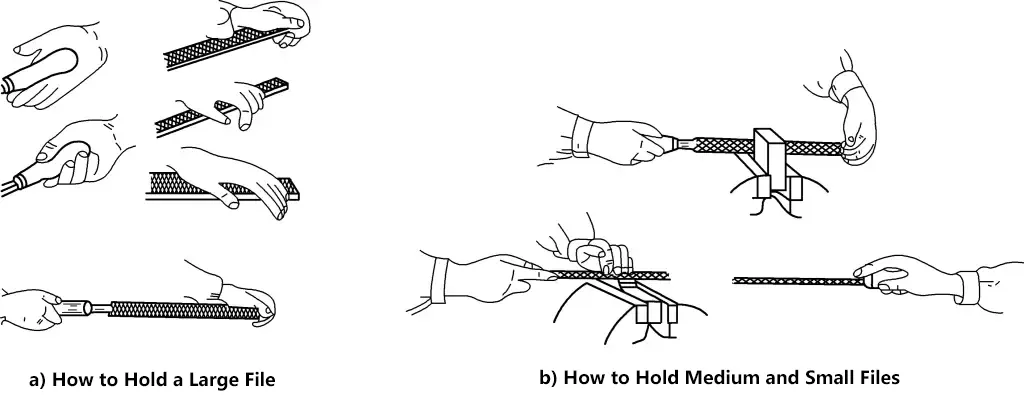
When using a large flat file, hold the file handle with your right hand and press the other end of the file with your left hand, keeping the file horizontal; when using a medium flat file, use the thumb and index finger of your left hand to pinch the front end of the file to guide it horizontally; for small files, hold them with your right hand.
(2) Applying Force
When initially pushing the file forward, at the starting position, apply more pressure with the left hand and less with the right hand. As you push forward, gradually change the pressure so that at the midpoint, both hands apply equal pressure. As you continue to file forward, gradually increase the pressure with the right hand and decrease the pressure with the left hand. This balances the torque between the hands, keeping the file moving horizontally. Otherwise, the file handle will tilt downward at the start, and the front end will tilt downward at the end, resulting in a surface that is low at both ends and raised in the middle.
3. Methods for Filing Planes
- Straight Filing: Filing perpendicular to the workpiece, used for filing flat or smooth surfaces.
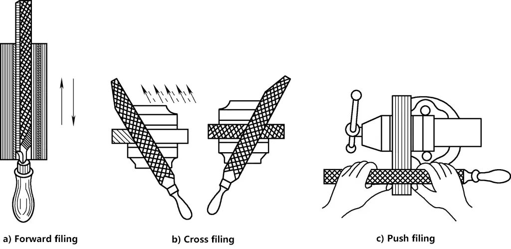
- Cross Filing: Filing at an angle of 30°~45° to the workpiece, alternating directions, mostly used for rough machining.
- Push Filing: Used when the material allowance is small or for smoothing, especially suitable for narrow surfaces or when straight filing is obstructed.
4. Methods for Filing Curved Surfaces
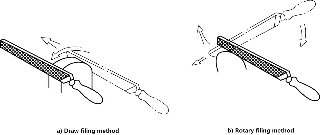
Use the rolling method, where the file’s movement follows a curved trajectory, rolling along the arc for filing.
5. Inspection of Filing Quality
(1) Use the light transmission method to check the straightness and perpendicularity of the filed surface. Use a steel ruler and a square ruler against the light; a thin, even line of light indicates a flat and straight surface.
(2) Use a steel ruler or caliper to check the dimensions of the workpiece.
6. Key Points of Filing Operation
(1) Holding the File
There are many types of files, with different specifications and sizes, and they are used in different situations. Therefore, the way of holding the file should also change accordingly. Figure 6a shows the method for holding a large file; Figure 6b shows the method for holding medium and small files.
(2) Filing Operation Posture
The filing operation posture is shown in Figure 7. The body weight is placed on the left foot, the right knee should be straight, and both feet should remain stable without moving, relying on the flexion and extension of the left knee to make a reciprocating motion. At the beginning, the body leans forward about 10°, and the right elbow is retracted as much as possible, as shown in Figure 7a.
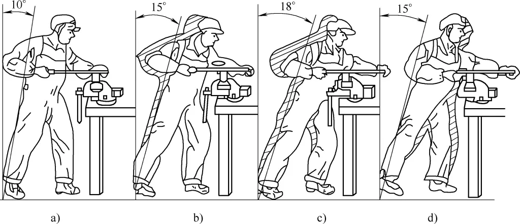
In the first 1/3 of the stroke, the body gradually leans forward to about 15°, and the left knee is slightly bent, as shown in Figure 7b. In the next 1/3 of the stroke, the right elbow pushes forward, and the body gradually leans forward to about 18°, as shown in Figure 7c.
In the last 1/3 of the stroke, the right wrist pushes the file forward, and the body naturally retreats to a position of about 15° while pushing the file forward, as shown in Figure 7d. After the filing stroke is completed, slightly lift the file, and the body posture returns to the starting position.
During the filing process, the force applied by both hands is constantly changing. At the beginning, the left hand applies more pressure and less pushing force, while the right hand applies less pressure and more pushing force. As the filing process continues, the pressure from the left hand gradually decreases, and the pressure from the right hand gradually increases. No pressure should be applied during the return stroke to reduce wear on the file teeth. The reciprocating motion speed of the file is generally 30-40 times/min, slower when pushing and faster during the return stroke.
(3) Flat Filing
There are three methods for flat filing: forward filing (Figure 8a), cross filing (Figure 8b), and push filing (Figure 8c). When filing a flat surface, the file should be used in a certain direction, and slightly moved during the return stroke to gradually file the entire surface flat.
(4) Curved Surface Filing
For external curved surfaces, a flat file is generally used. The commonly used filing methods are forward filing and rolling filing. Forward filing, as shown in Figure 9a, is filing across the arc direction, which can file the surface into a polygonal shape close to the arc (suitable for rough machining of curved surfaces). Rolling filing, as shown in Figure 9b, involves pressing down with the right hand and lifting with the left hand while filing forward, making the file rotate on the workpiece arc.
V. Hole Machining
Hole machining refers to drilling, reaming, countersinking, and boring on a drilling machine.
Key points of hole machining operation: Generally, the hole machining tool should perform two movements simultaneously, as shown in Figure 10. The main movement is the rotation of the tool around its axis (indicated by arrow 1); the feed movement is the linear motion of the tool along the axis towards the workpiece (indicated by arrow 2).
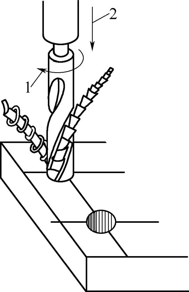
1—Main Movement
2—Feed Movement
1. Drilling
(1) Standard Twist Drill
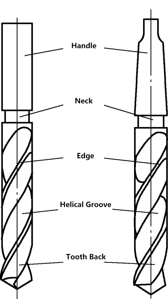
The standard twist drill, as shown in Figure 11, is the main tool for drilling. The twist drill is made of high-speed tool steel, and the working part is heat-treated and hardened to 62~65HRC. The twist drill consists of a shank, a neck, and a working part.
1) Drill Shank.
The drill shank is used for clamping and transmitting power. There are two types of shanks: straight shank and taper shank. The straight shank transmits less torque and is used for drills with a diameter of less than 13mm. The taper shank has good centering and transmits more torque, used for drills with a diameter greater than 13mm.
2) Neck.
The neck is the relief groove for grinding the working part and machining the drill shank. The diameter, material, and trademark of the drill are generally engraved on the neck.
3) Working Part.
It is divided into a guiding part and a cutting part.
As shown in Figure 11, the guiding part relies on two narrow helical ridges (cutting edges) that are 0.5~1mm higher than the back of the teeth to provide guidance. The diameter of the guiding part is larger at the front and smaller at the back, with a slight taper. The taper is 0.03~0.12mm/100mm, which can reduce friction between the drill bit and the hole wall. The guiding part has two symmetrical helical grooves formed by milling, grinding, or rolling, which are used to remove chips and transport cutting fluid.
(2) Workpiece Clamping
As shown in Figure 12, the method of clamping the workpiece during drilling is related to the production batch size of the workpiece and the processing requirements of the hole.
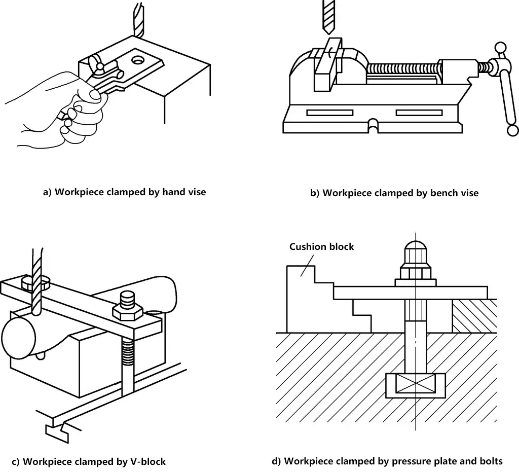
When the production batch size is large or the precision requirements are high, the workpiece is generally clamped using a drill jig; for single-piece small batch production or lower processing requirements, the workpiece is usually clamped on a general fixture or workbench after marking the center position of the hole. Common accessories include hand vises, V-blocks, flat-nose pliers, and pressure plates and bolts, etc. The selection of these tools is related to the shape of the workpiece and the size of the hole diameter.
(3) Drill Bit Clamping
The method of clamping the drill bit varies according to the shape of its shank. Taper shank drill bits can be directly installed into the taper hole of the drill press spindle, while smaller drill bits can be installed using a transition sleeve, as shown in Figure 13a. Straight shank drill bits are installed using a drill chuck, as shown in Figure 13b.
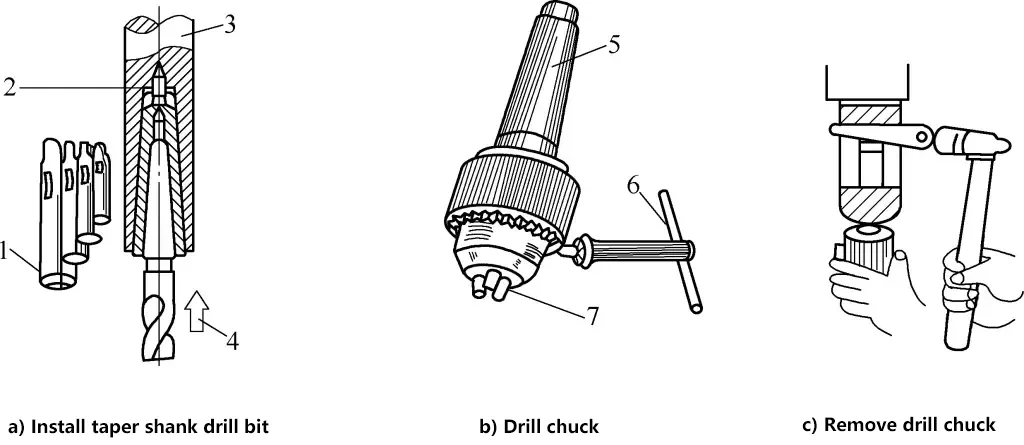
1—Transition Sleeve
2—Taper Hole
3—Drill Press Spindle
4—Push the drill bit upward during installation
5—Taper Shank
6—Tightening Wrench
7—Automatic Centering Jaws
The method for removing the drill chuck (or transition sleeve) is to insert a wedge iron into the flat hole on the side of the drill press spindle, hold the drill chuck with the left hand, and use a hammer to tap the wedge iron with the right hand to remove the drill chuck, as shown in Figure 13c.
(4) Drilling Method
Before drilling, use a center punch to make a center punch mark on the center line of the hole, align the drill tip with the center punch mark to make a small pit, and check whether the small pit is concentric with the drawn circle of the hole (called trial drilling). If there is a slight deviation, the workpiece can be moved to correct it. If the deviation is large, use a chisel or center punch to make several grooves in the opposite direction of the deviation, as shown in Figure 14.
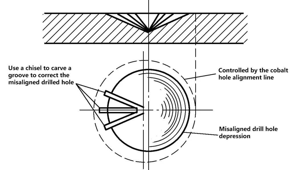
For smaller diameter holes, you can also use a shim to raise the workpiece slightly in the direction of the deviation before drilling. Only when the small pit drilled is complete and concentric with the drawn circle of the hole can formal drilling begin.
To prevent the drill bit from annealing during drilling, cutting fluid should be added. Use machine oil or emulsion for steel parts, water for aluminum parts, and kerosene for cast iron parts. When the hole is about to be drilled through, the force should be reduced.
2. Reaming
Reaming is the process of enlarging an already drilled hole using a reamer. Special reamers generally have 3~4 main cutting edges, no transverse edges, shallower helical grooves, smaller axial cutting force, and good guiding properties, as shown in Figure 15. Therefore, the reamer core is thick, has good rigidity, and is not easily deflected.

Reaming can achieve higher dimensional accuracy (dimensional tolerance grade can reach IT9~IT10) and smaller surface roughness values (Ra3.2~6.3μm). The accuracy of reaming is higher than that of drilling.
3. Counterboring
Counterboring refers to the process of using a counterbore to machine a certain shape of hole or surface on the surface of a hole. Counterbores are divided into cylindrical counterbores, conical counterbores, and end face counterbores.
4. Reaming
Reaming is a machining method that uses a reamer to remove a small amount of metal from the wall of a hole to improve the dimensional accuracy and surface quality of the hole. Reaming is a further finishing process after reaming and can be divided into rough reaming and finish reaming. When reaming, a machining allowance should be left, generally 0.1~0.2mm for rough reaming and 0.05~0.15mm for finish reaming.
Machinists often use hand reamers for reaming holes. Reaming holes achieves high dimensional accuracy (dimensional tolerance grade can reach IT6~IT8) and low surface roughness (Ra0.4~1.6μm). When drilling, enlarging, and reaming holes, appropriate cutting fluid should be selected based on the nature of the work and the material of the workpiece to reduce cutting temperature and improve processing quality. When reaming, use emulsified oil for steel parts and kerosene for cast iron parts.
(1) Reamer
A reamer is a finishing tool for holes. Reamers have 6 to 12 cutting edges and are divided into machine reamers and hand reamers. Machine reamers have a tapered shank, while hand reamers have a straight shank. Figure 16 shows a hand reamer. Reamers are generally made in sets of two, one being a rough reamer (with spiral chip flutes on its edge) and the other a finish reamer.
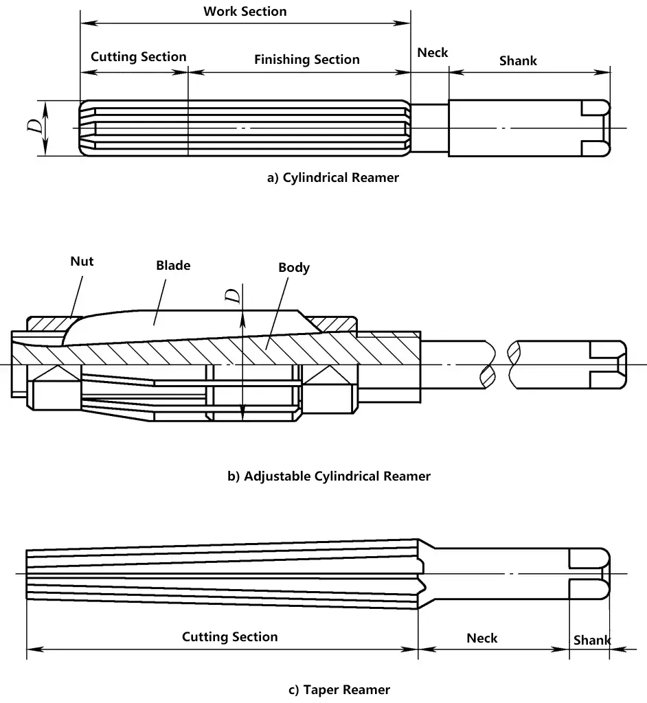
(2) Hand Reamer Reaming Method
Insert the hand reamer into the hole, hold the reamer handle with both hands, turn it clockwise and apply slight pressure to slowly feed the reamer into the hole. Ensure that the force applied by both hands is balanced so that the reamer remains perpendicular to the workpiece during reaming. When withdrawing the reamer, also turn it clockwise while pulling it out.
VI. Tapping and Threading
1. Tapping
Tapping is the process of using a tap to create internal threads.
(1) Structure of the Tap
A tap is a forming tool used to create small diameter internal threads, as shown in Figure 17. It consists of a cutting part, a calibration part, and a shank. The cutting part is ground with a taper angle to distribute the cutting load across several teeth. The calibration part has a complete tooth profile to calibrate the cut threads and guide the tap along the axial direction. The shank has a square end for easy installation and torque transmission.

The cutting and calibration parts of the tap generally have 3-4 chip flutes along the axial direction to accommodate chips and form cutting edges and rake angles γ o . The cutting part’s taper surface is ground with a relief angle α o . To reduce friction and extrusion of the workpiece material by the tap’s calibration part, both the outer and middle diameters have a back taper.
Taps are generally available in sets of two, and for pitches above 2.5mm, in sets of three.
A set of two taps includes a taper tap and a second tap. The taper tap has a longer cutting part and a smaller taper angle, with about six incomplete teeth. The second tap has a shorter cutting part and a larger taper angle, with 2-3 incomplete teeth. The first cut removes about 60% of the material, and the second cut removes about 40%, making it less likely for the tap to break inside the workpiece and reducing the risk of scrapping the workpiece.
A set of three taps includes a taper tap that cuts about 50%, a second tap that cuts 30%, and a third tap that cuts 20%, making it more efficient and less likely to break the tap.
(2) Determining the Pre-Tap Hole
Since the tap itself cannot drill holes and can only cut threads, a hole must be drilled with a drill bit before tapping. This hole is usually called the “pre-tap hole.” The diameter of the pre-tap hole d (drill bit diameter) is slightly larger than the minor diameter of the thread. It can be calculated using empirical formulas.
For tough materials (steel, copper, etc.) d2 = d – P
For brittle materials (cast iron, bronze, etc.) d2 = d – 1.1P
Where
- D – Basic size of the thread (mm);
- P – Pitch (mm).
If the hole is a blind hole, since the tap cannot reach the bottom, the drilling depth should be greater than the thread length. The depth can be calculated using the formula: Hole depth = Thread length + 0.7D.
(3) Tapping Method
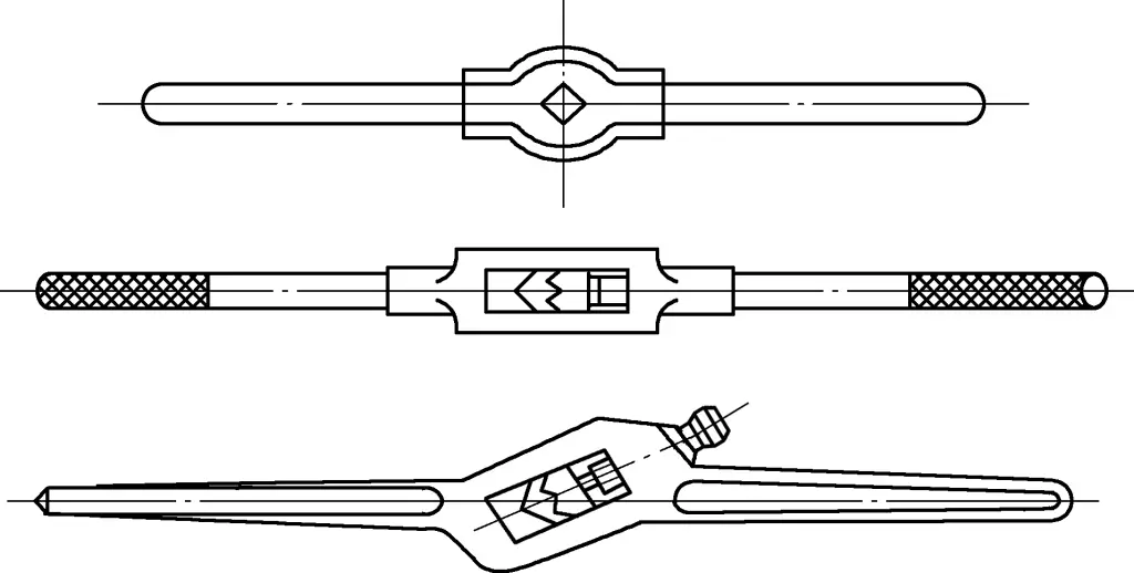
1) Insert the tap into the tap wrench, then place the tap into the pre-tap hole. A hand tap wrench is a tool for turning the tap, as shown in Figure 18. Common tap wrenches include fixed and adjustable types to hold taps of various sizes.
2) Turn the tap wrench with both hands, as shown in Figure 19, and apply axial pressure. When the tap cuts into the workpiece by 1-2 teeth, check with a square to ensure the tap is not tilted. If the tap is tilted, correct it before continuing. Once the tap is perpendicular to the end face of the pre-tap hole, stop applying axial pressure.

Apply even force with both hands. To prevent chip clogging, frequently reverse the tap by 1/2 to 1/4 turn to break the chips. After the taper tap is finished, switch to the second tap and use the same method to create the required internal threads. To reduce surface roughness and resistance, apply lubricant during tapping. Use machine oil for steel, water for aluminum, and kerosene for gray cast iron.
2. Threading
Threading is the process of using a die to create external threads on a round rod.
(1) Die and Die Holder
A die is a tool for creating external threads, as shown in Figure 20. It resembles a round nut but has several chip holes drilled into it, forming cutting edges. The tapered sections at both ends of the die are the cutting parts. These are ground to form Archimedean spiral surfaces with a certain relief angle. The middle section is the calibration part, which also serves as the guide during threading. When the cutting part at one end wears out, the die can be reversed for use.
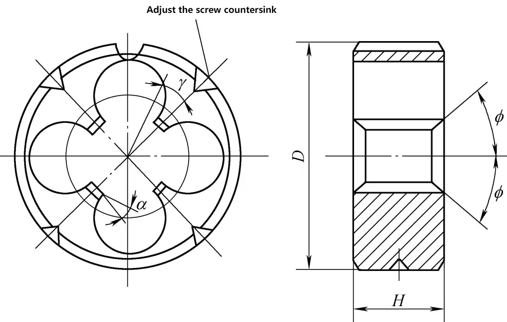
The accuracy of threading with a die is relatively low. It can be used to process threads with a dimensional tolerance band of 8h and a surface roughness value of Ra3.2~6.3μm. Dies are generally made of alloy tool steel 9SiCr or high-speed tool steel W18Cr4V.
A die holder is needed for manual threading, as shown in Figure 21.

(2) Threading Method
1) Determine the diameter of the rod for threading
The diameter of the screw rod can be directly looked up in a table or calculated using the empirical formula d=D-0.13P. For threads with low precision requirements, the rod diameter is approximately equal to the thread outer diameter minus 0.2P.
2) Chamfer the rod at a 60° angle at the threading position to facilitate positioning.
3) Install the die into the die holder and tighten the fixing screw.
4) Place the die on the chamfered end of the rod, as shown in Figure 22, and keep the die perpendicular to the rod. Hold the middle part of the die holder with your right hand, apply appropriate pressure, and turn the handle of the die holder clockwise with your left hand. When the die cuts into the rod for 2-3 threads, check if the die is skewed. If skewed, correct it before continuing. Once the die is correctly positioned, no additional pressure is needed for further threading.
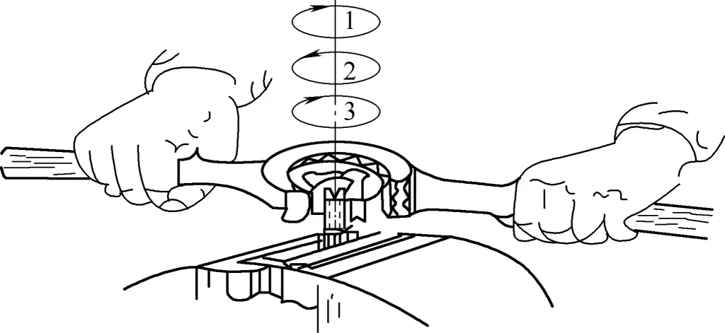
Like tapping, threading should frequently reverse to break the chips. Cutting fluid should be used during threading to ensure the surface roughness requirements of the thread.
3. Causes of Defects in Tapping and Threading
The causes include inappropriate selection of the hole diameter and rod diameter, and the tool not being perpendicular to the workpiece, resulting in skewed threads.
VII. Inspection Tools and Their Use
Inspection tools include knife-edge straight rulers, squares, and vernier universal protractors. Knife-edge straight rulers and squares can inspect the straightness, flatness, and perpendicularity of workpieces. The following introduces the method of using a knife-edge straight ruler to inspect the flatness of a workpiece.
1. Place the knife-edge straight ruler vertically against the workpiece surface and check successively in the longitudinal, transverse, and diagonal directions, as shown in Figure 23.
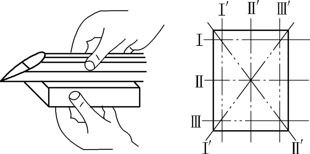
2. During inspection, if the light passing through between the knife-edge straight ruler and the workpiece surface is weak and uniform, the flatness of the part is qualified. If the light varies in intensity, it indicates that the workpiece surface is uneven. A feeler gauge can be inserted at the contact points between the knife-edge straight ruler and the workpiece to determine the flatness error based on the thickness of the feeler gauge, as shown in Figure 24.


