The automated stamping production line consists of the main machine and peripheral equipment, capable of achieving high-speed, automated, and flexible stamping processes. The main machine refers to various presses and necessary other machining tools that complete the stamping operations, while peripheral equipment refers to various automated devices, detection devices, control systems, etc., required to complete various auxiliary tasks in automatic production.
The degree of automation of the production line, the combination mode of the press, the type and function of the automation devices, and the control system should be determined based on factors such as the shape and size of the product, stamping process, production scale, and production conditions. The design, manufacture, and use of automated stamping production lines should take into account both technical advancement and economic rationality.
The blanks used on the automated stamping production line are divided into two main categories: coil and sheet materials, which should correspond to different types and functions of automation devices. For example, large automated stamping production lines for automotive body parts typically use sheet material as blanks after cutting.
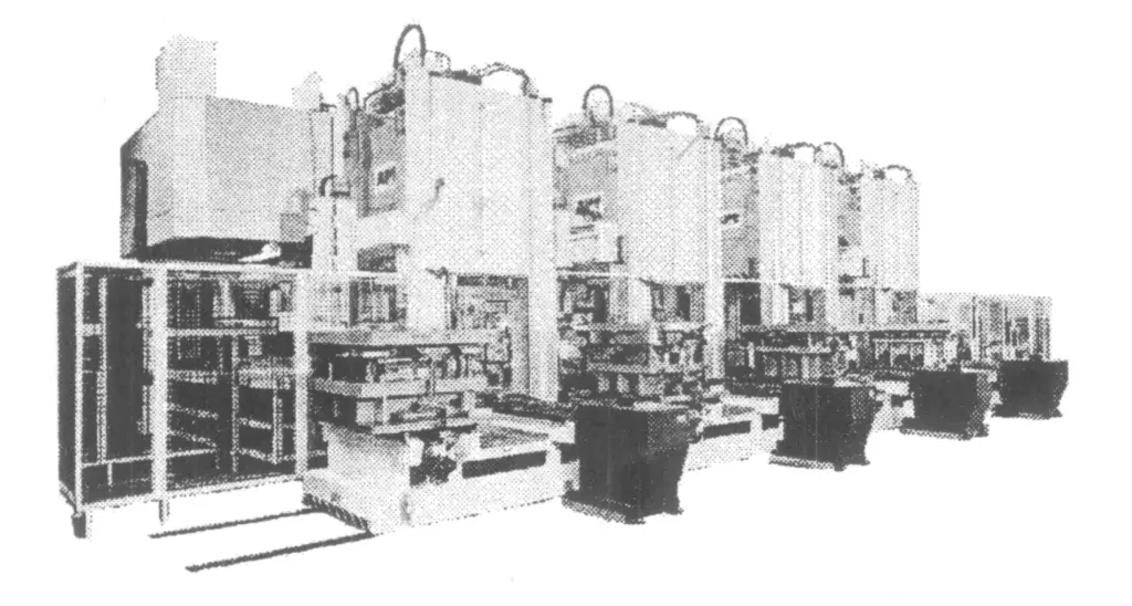
Commonly used automation devices include: destacking feeding devices, cleaning and oiling machines, centering feeders, loading and unloading robots (or manipulators), belt conveyors, shuttle carts, rapid mold changing devices, end-of-line equipment, etc. This type of stamping production line often adopts a serial workshop layout (see Figure 1), with presses and inter-process conveyors arranged in a straight line.

1—Automatic Feeding Device
2—Press
3—Conveying Device
4—Output mechanism
High-speed presses often use rolled material as blanks. Common automation devices include: uncoilers, leveling machines, cleaning and oiling machines, pneumatic feeders, end equipment, etc. Relevant technical parameters should be determined based on the blank material, shape, size of the parts, and other technical requirements.
According to the characteristics of the connection between processes, automated stamping production lines can be divided into rigid connection lines and flexible connection lines. On a rigid connection line (see Figure 2a), the conveying devices between equipment are rigidly connected, there are no semi-finished product reserves between processes, and strict synchronization of each equipment is required. The disadvantage is that when a part fails, the entire production line needs to be stopped.
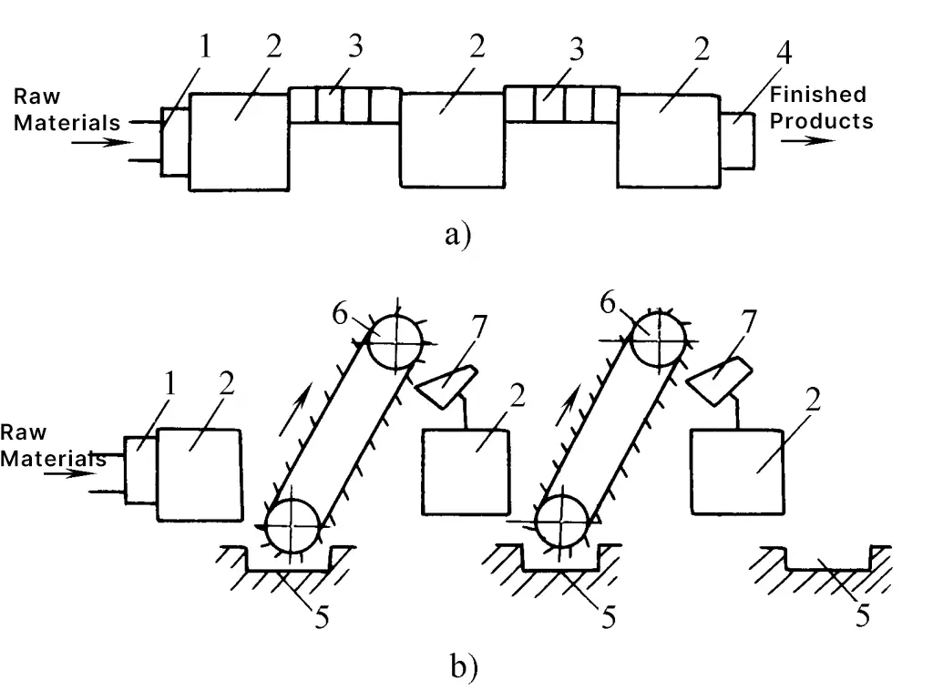
a) Rigid connection line
b) Flexible connection line
1—Automatic feeding device
2—Press
3—Conveying device
4—Output mechanism
5—Storage device
6—Elevator
7—Hopper
On the flexible contact line (see Figure 2b), storage devices and hoppers are placed between equipment to store a portion of the semi-finished products, thus absolute coordination between equipment is not necessary. When an individual device fails, it is allowed to stop for a short time without needing to stop the entire line. The downside is that the production pace of the production line must be determined by the equipment with the lowest production rate, resulting in lower equipment utilization.
I. Large-scale automated stamping production line
The large-scale automated stamping production line is mainly used for stamping production of large parts such as automotive body panels, usually consisting of several large presses arranged in series, with production efficiency more than doubling compared to manual lines. Common types of automation devices include stamping manipulators, robots, claw-type conveying systems, swinging crossbar conveying systems, and rapid crossbar conveying systems.
The first domestically produced large-scale automated stamping production line with international advanced level was put into use in September 1995 at Chongqing Changan Automobile Company, designed and manufactured in cooperation between Jinan Second Machine Tool Factory and American SI Robotics Company, based on the transformation of an existing manual operation press production line.
The automation system consists of 1 set of destacking feeding devices, 5 sets of loading manipulators, 5 sets of unloading manipulators, 4 sets of shuttle transfer devices, 10 operating stations, and 5 sets of control electrical cabinets.
In 1997, the Robotics Engineering Department of the Shenyang Institute of Automation, Chinese Academy of Sciences, developed an automated stamping production line for Jetta sedan body panels for FAW-Volkswagen, consisting of 6 presses, 6 sets of loading manipulators, 6 sets of unloading manipulators, 1 flipping transfer device, 4 shuttle transfer devices, and 1 magnetic stratification device.
1. Stamping manipulators, robots
Stamping manipulators and robots can simulate manual actions to complete automatic loading and unloading, featuring good production flexibility and high production efficiency. They can meet the needs of flexible production of multiple varieties and medium to large batches. They can either form a single-machine automated stamping unit with a single press or an automated stamping production line with multiple presses, making them widely used automated stamping conveyance devices.
Stamping robots and manipulators usually use vacuum suction cups to grab workpieces, allowing for rapid overall replacement and disassembly, adapting to the production needs of stamped parts of different shapes and sizes, and effectively avoiding scratches and abrasions on the surface of the workpieces. During movement, the vacuum suction cups must not interfere with the press, molds, etc.
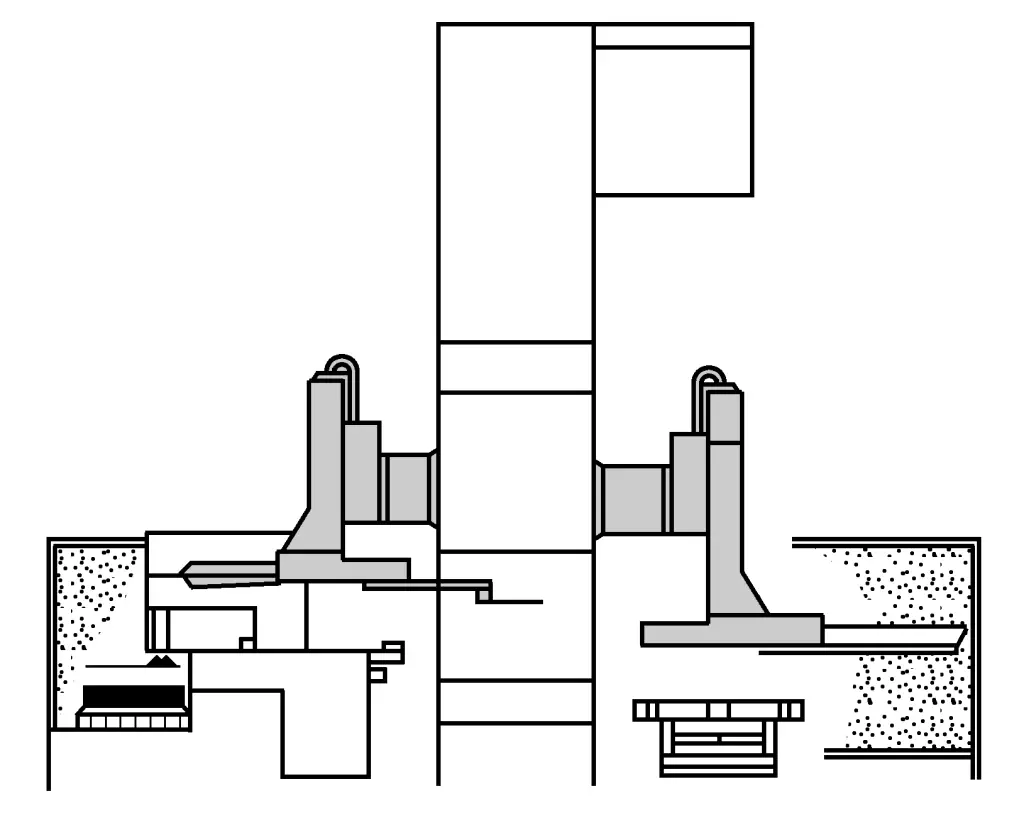
The stamping manipulator is mounted on the front or back of the press column or upper beam, as shown in figure 3. According to their function, they can be divided into loading and unloading manipulators, both of which have similar mechanical structures and operating principles, respectively completing the actions of transferring the sheet metal from the pickup station to inside the mold, and removing the formed workpiece from the mold and transferring it to the pickup station of the next press.
Based on the driving method of the vacuum suction cups, stamping manipulators are divided into types such as linear, swing arm, and composite. They can be designed and manufactured according to specific site conditions and technical requirements. Figure 4 shows two types of loading and unloading manipulators developed by Sweden’s AP&T company, with the CD type being linear and the FA type being swing arm, capable of handling a maximum weight of 100kg.
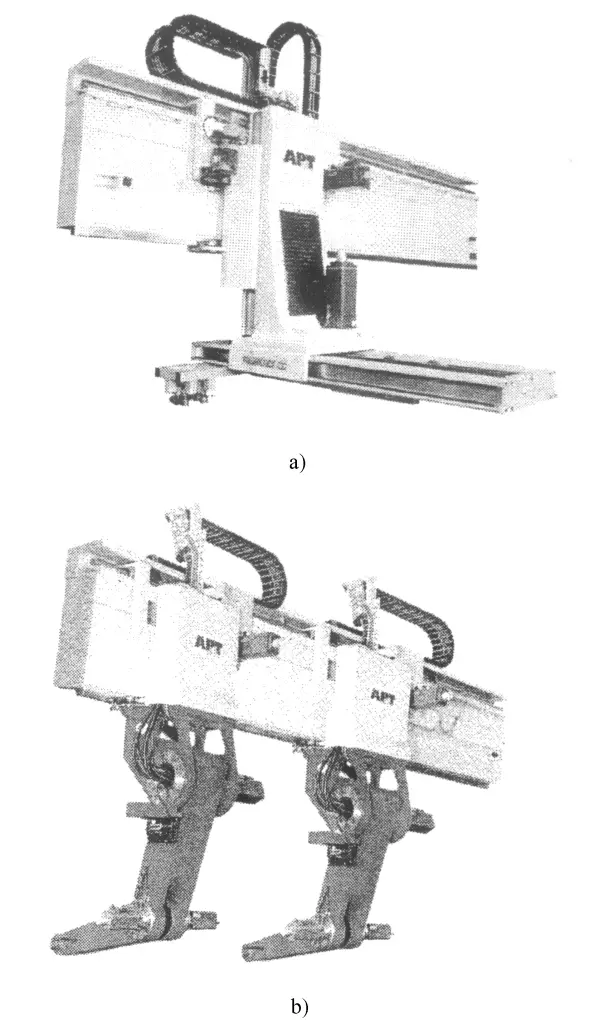
a) CD type
b) FA type (dual manipulator)
The characteristic of stamping robots is their high flexibility, with no mechanical connection to the press, which facilitates standardized production and easy installation and adjustment. The downside is slightly lower production efficiency and unsuitability for long transport distances. Stamping robots typically use AC servo motors for driving, with flexible adjustment of speed, travel, and other parameters, and can achieve multi-axis linkage to perform various complex spatial trajectories.
Before working, the stamping robot should be programmed for its actions and tasks to coordinate with the press, achieving continuous trajectory control. The main programming methods include offline programming, online teaching, and a combination of offline planning and online teaching.
Famous companies producing robots internationally include ABB, KUKA, etc. KUKA robots support various standard industrial control buses, including: Interbus, Profibus, Devicenet, Canbus, Control-net, EtherNet, Remote I/O, etc. By installing Soft PLC software, the robot can directly control the entire production line, and even the entire workshop. The robot is equipped with a portable teaching device, which can achieve flexible and rapid action programming.
2. Rapid crossbar conveying system
In 2004, Germany’s Müller Wanjia Dun Corporation successfully developed a rapid crossbar-style automated conveying system (SpeedBAR) for use in tandem press production lines. This is an automated conveying mechanism that lies between conventional robotic arms and multi-station press crossbar conveying systems, featuring flexibility, simplicity, speed, and efficiency. It can effectively ensure high flexibility of products and high efficiency of production, reducing equipment investment and production costs.
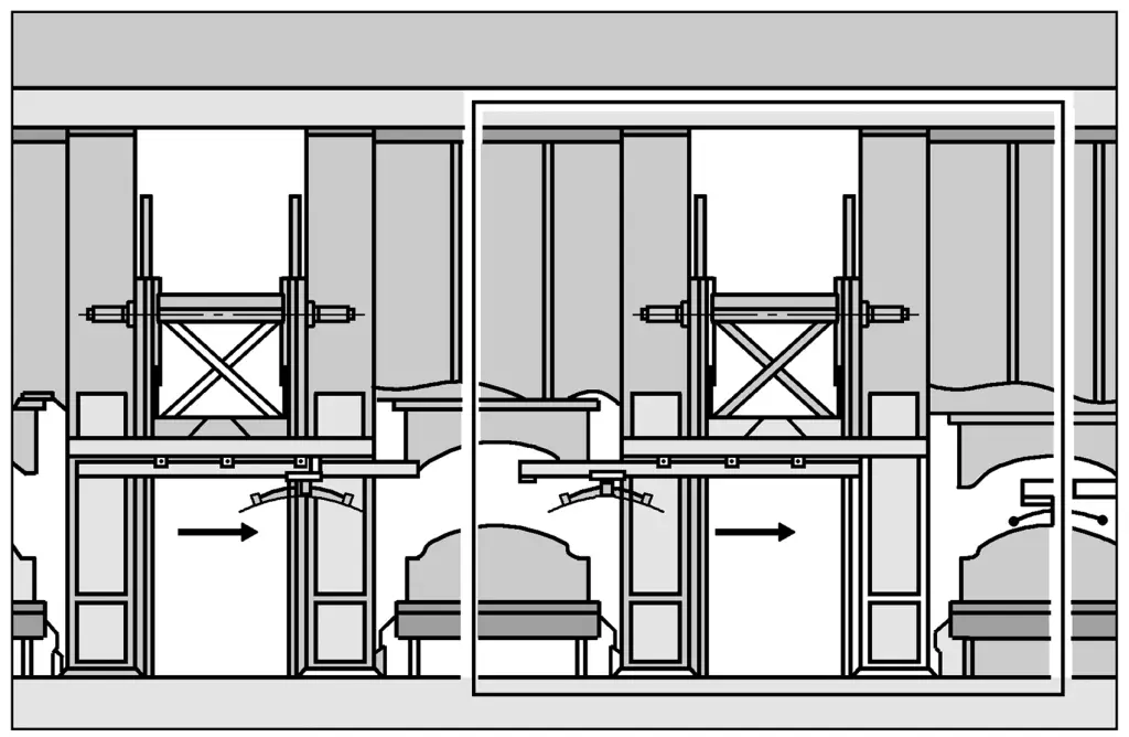
As shown in Figures 5 and 6, the rapid crossbar conveying system consists of several modularized transmission units fixed between the columns of the press, driven by servo motors, equipped with two telescopic guide rails along the direction of motion. By installing suction cup end pickers on the telescopic guide rails, parts can be picked up from one press and directly delivered to the next press without the need for intermediate transmission stations.
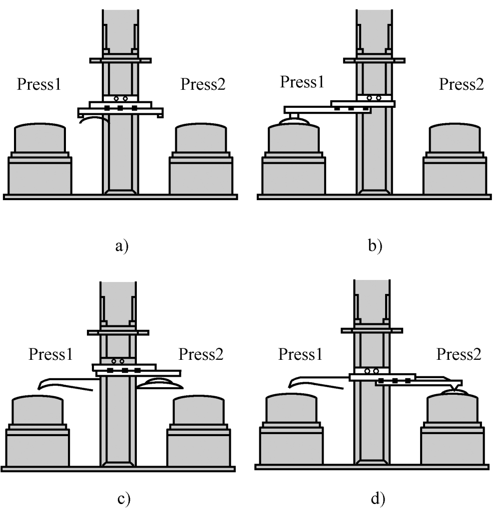
a) Starting position
b) Picking up
c) Conveying
d) Placing
The main technical features are as follows:
(1) Only one set of monolithic linear conveyors connects the two presses, with no intermediate transition stations, reducing the number of automation devices.
(2) The mechanical structure of the conveyor is highly rigid, the motion process is smooth and reliable, which can significantly increase the conveying speed and improve the production rhythm.
(3) No need for shuttle carts, which shortens the center distance between presses and reduces the footprint of the stamping production line.
(4) The end effector is mounted on a crossbar guided by rails on both sides according to the shape of the workpiece, and its effective area can cover the entire worktable of the front and rear presses.
(5) The built-in multi-degree of freedom adjustment device on the crossbar allows for adjustments up to 5 degrees of freedom, enabling arbitrary repositioning of the workpiece between two stations (see Figure 7). The functions of each CNC axis are as follows:
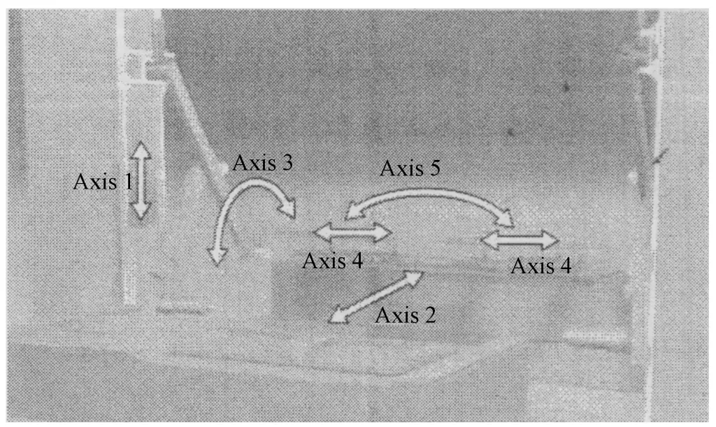
- Axis 1 (Axia1): Workpiece lifting, lowering;
- Axis 2 (Axia2): Workpiece advance, return;
- Axis 3 (Axia3): Workpiece rotation;
- 4-axis (Axia4): Lateral movement of the workpiece;
- 5-axis (Axia5): Workpiece tilting.
In addition to SpeedBAR, Miller Wanjia Dun’s automatic conveying system also includes Swingarm, Swivelarm, etc.
3. Destacking feeding device
The function of the destacking feeding device is to correctly separate the sheets from the stack according to the given production beat and sequentially transport them to the pickup station of the first press feeding device.
The device usually consists of a pallet, lifting device, magnetic separation and dual material detection device, suction lifting device, magnetic belt conveying device, cleaning and oiling device, sheet conveying device, centering positioning device, etc.
4. Shuttle conveying device
When technically retrofitting an active stamping production line, it is usually not possible to move the installation position of the press. To meet the requirements of long-distance transportation of workpieces between two presses and to improve the production efficiency of the production line, a shuttle conveying device should be set up according to the on-site conditions. For production lines starting with a double-action press, a workpiece flipping mechanism should also be attached between the first and second presses.
5. Electrical control system
The automated stamping production line is a complex system composed of multiple links and multiple devices. The control systems for setting, adjusting, interlocking, and protecting various devices in the production line are very complex. If any link such as the press, mold, materials, robot itself, transmission device, or pneumatic system has a problem or does not meet the requirements of automated production, it will directly affect the smooth operation of the entire production line. The monitoring system can detect abnormal factors during the stamping process and make reasonable judgments and handling.
The main machine of the production line and the surrounding equipment are interconnected through control interfaces to transmit control information, motion information, and fault information, achieving linkage and interlocking between workpiece conveyance and the movement of the press slider.
Traditional control systems use centralized control methods. With the development of technologies such as field buses, distributed I/O, and network digital communication, the distributed I/O control method based on field buses has been widely adopted.
Distributed control methods have advantages such as fast response times and large data transmission capacities. Component signals are processed nearby, and actuators and sensors are directly connected to the automation system, with signals transmitted to the processor via a data bus. This reduces intermediate links and improves response times.
Remote fault diagnosis and system maintenance using an Internet-based remote fault diagnosis system can effectively shorten fault handling time and reduce maintenance costs, and its application is becoming increasingly widespread. Through network technology, information transfer between different devices can be achieved and connected to the factory’s production management network.
II. High-speed press automated stamping unit
In the production field of small electronic components such as IC lead frames and connectors, high-speed presses are the main processing equipment. Under conditions of a nominal pressure of 100kN and a nominal pressure stroke of 8mm, the slider stroke frequency has reached up to 4000 times/min. Blanks are usually in coil form, and the automated stamping device consists of an uncoiler, leveler, cam-driven feeder and collector, and a detection control system, forming a unified whole with the main machine.
For more information on the high-speed press main machine, please refer to Volume III of this manual. Since the slider stroke frequency of the high-speed press is much higher than that of ordinary presses, the performance and reliability of peripheral equipment are of great significance to ensure safe, reliable, and stable production processes.
The feeding rhythm of the automatic feeding mechanism should be strictly synchronized with the press. When the slider moves downward to start stamping on the lower mold, the feeding mechanism should have completed the feeding action. After stamping ends, the slider drives the upper mold to return, and feeding can only begin after the upper mold has completely exited from the material.
For molds equipped with guide pins, the feeding mechanism must also have a clamp relaxation function, so that the material is in a floating state before the upper mold punches into the material, with the guide pins providing precise positioning. Before the guide pins exit the material, it should return to a clamped state.
Main types include: roller feeding devices with irregular roller overrunning clutches, with a maximum feeding rhythm of about 800 times/min and feeding accuracy of ±0.05mm; roller feeding devices with worm cam and roller gear indexing mechanisms, with a maximum feeding rhythm of 2000 times/min and feeding accuracy of ±0.02mm; pendulum roller and clamp-type feeding devices; pneumatic feeding devices, etc.
III. Small and Medium-sized Press Automation Stamping Unit
Equipping a general-purpose small and medium-sized press with an automatic feeding device can form a single-machine automated stamping unit, achieving single or multiple process automation and continuous stamping, improving production efficiency and the flexibility of the production process.
Figure 8 shows an automated stamping unit for small and medium-sized presses developed by Sweden’s AP&T company, used for producing household electric oven panel parts, with a variety of products and large production volumes.
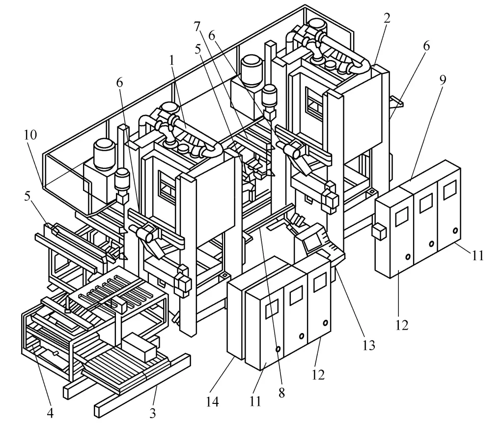
1, 2—Hydraulic Press
3—Stacking Platform
4—Pallet Unloading Machine
5, 7—Mold Changing Guide Rails
6—Loading and Unloading Robot
8—Transmission Transfer Table
9—Workpiece output conveyor belt
10—Maintenance platform
11, 12, 14—Electrical cabinet
13—Central control console
The production line consists of two 4000kN hydraulic presses, four loading and unloading robotic arms, one palletizing loader, and a rapid mold change system, capable of performing various processes such as blanking, deep drawing, and forming, with a production rate of 5 to 8 cycles/min. The blank specifications range from a maximum of 1200mm x 1000mm to a minimum of 300mm x 300mm. The action process is as follows.
First, the stack pallet is sent to the stacking platform, the de-stacking arm with a vacuum suction cup moves downward, grabs the top sheet metal, and a dual material detection device automatically checks if the sheet metal is unique. After confirmation, the sheet metal is sent to the transfer platform for cleaning, lubrication, positioning, and loaded onto the first hydraulic press by the loading robot with a vacuum suction cup.
After the stamping is completed, the unloading robot installed on the other side of the press takes the formed parts out of the mold, places them on the transfer table, and the second hydraulic press and its loading and unloading robots complete the second stamping process. The stamped parts are then conveyed out of the machine via a conveyor belt.
Figure 9 shows an automatic thrust washer stamping line, suitable for the stamping production of various types of thrust washers, with a production capacity of 8.2 million pieces/year. This production line can automatically complete the entire process of thrust washer stamping production, including: raw material cleaning, oil brushing, stamping (cutting, bending, forming), stamped parts queuing, automatic boxing, etc.
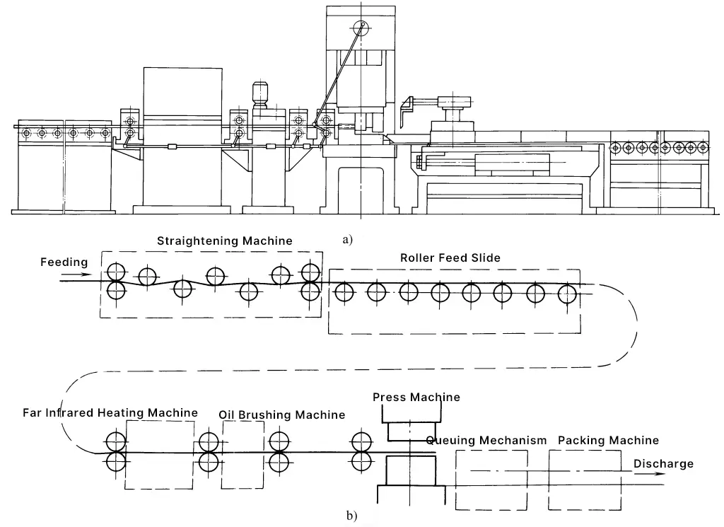
a) Automatic line outline diagram
b) Automatic line flowchart
The entire line consists of a straightening machine, roller-type feed slide, far-infrared heating machine, oil brushing machine, press, queuing mechanism, boxing machine, and control desk, etc. It is suitable for many types of transmission mechanisms for medium and small press automation stamping units, which should be designed and manufactured according to specific connection requirements. Table 1 lists several commonly used conveying mechanisms.
Table 1 Conveying Mechanisms of Stamping Automatic Line
| Type | Structural Features | Working Features |
| Gravity, inertial force conveyors | 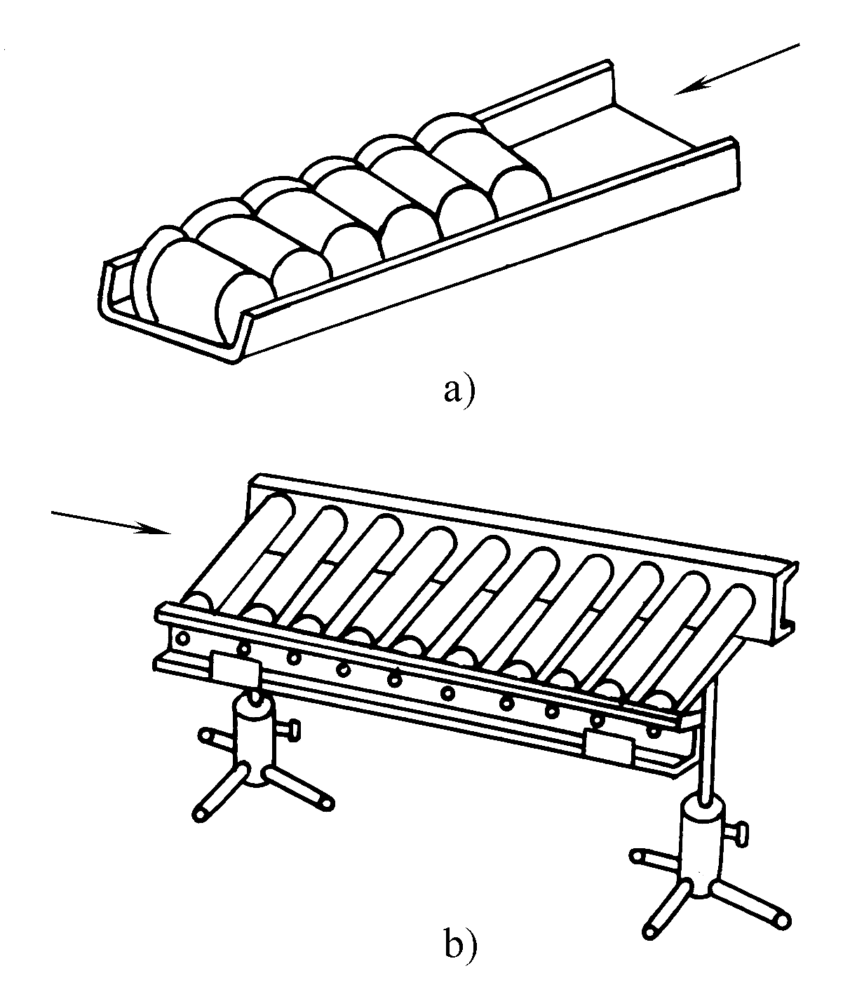 a) Flow trough b) Roller path | Utilizes the gravity of the parts themselves or the inertial force acting on the parts after processing to achieve the conveyance of the parts |
| Belt and chain conveyors |  | Continuously convey parts through mechanical transmission. During processing, parts must be removed from the conveyor, thus additional loading and unloading mechanisms are required. |
| Scraper type elevator | 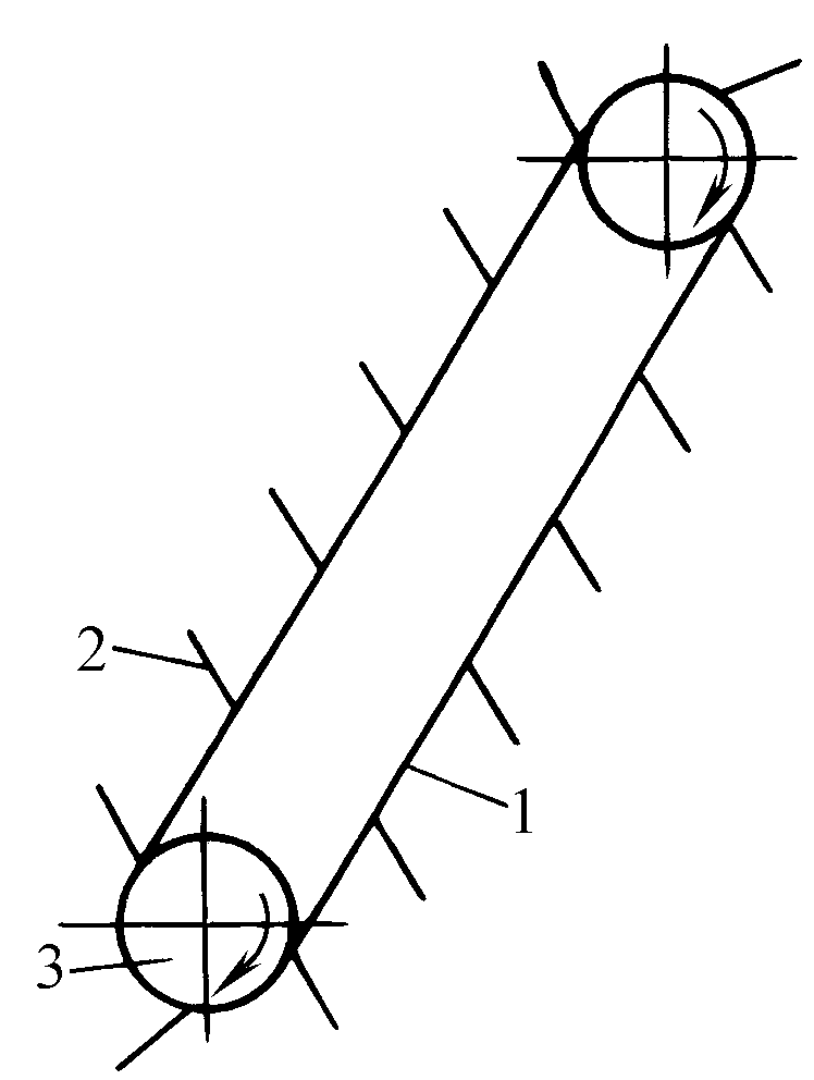 1—Conveyor belt 2—Scraper 3—Guide wheel | Utilizes a slide to directly slide parts onto the conveyor belt to be carried away by the scraper. Low manufacturing cost, wide range of applications. |
| Bucket type elevator | 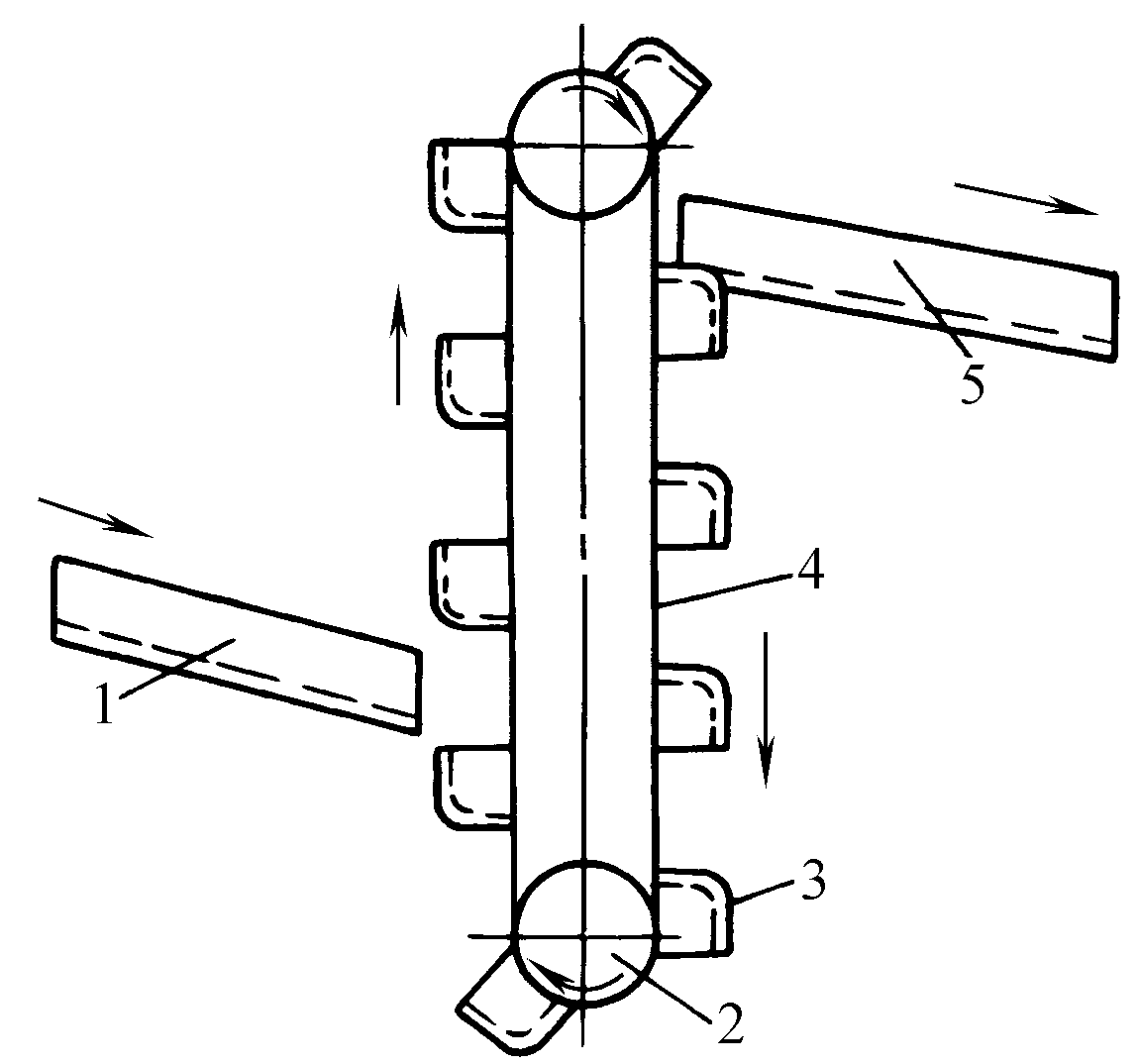 1—Slide 2—Drive wheel 3—Bucket 4—Belt 5—Receiving plate | Generally used for vertical lifting, can be inclined to 65°~75° when needed, the working speed of the belt is about 0.2~0.4m/s |
| Chain type elevator | 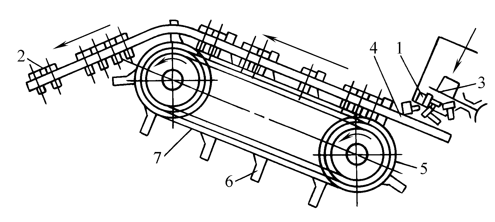 1—Hopper 1—Hopper 2—Blank 3—Spiral cam 4—Guide groove 5—Sprocket 6—Selector 7—Chain | The cam 3 stirs so that the tail of the blank falls into the inclined guide groove, while the head rests on the shoulder of the groove, being moved by the selector on the chain, commonly used for rod-type parts with heads |
| Shuttle conveyor | 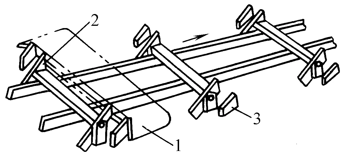 1—Workpiece 1—Workpiece 2—Feed claw 3—Fixed claw | The push plate equipped with feed claws reciprocates linearly to push the workpiece, and the workpiece that has been fed is blocked by the fixed claw 3 (backstop) and does not return |
| Vacuum suction cup flipper | 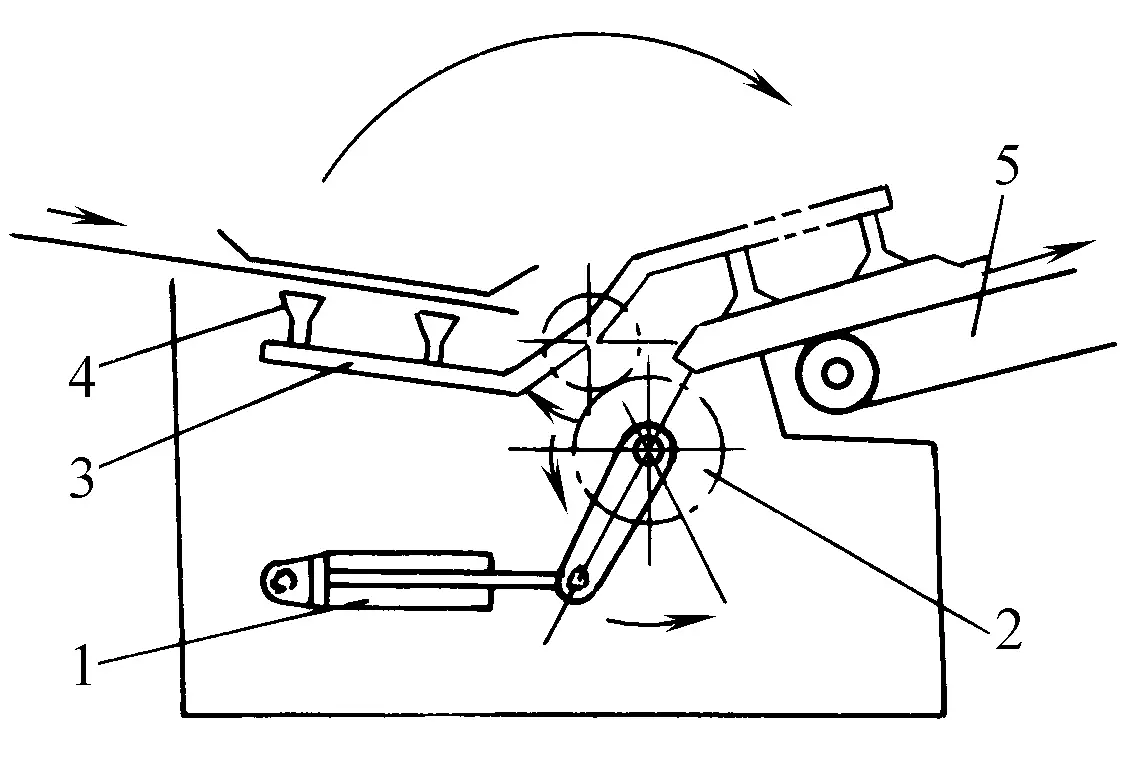 1—Cylinder 2—Gear 3—Flip plate 4—Vacuum suction cup 5—Conveyor belt | Use the flipper to flip the workpiece 180°, then the conveyor and feeder send it to the next press |
| Plate flipper | 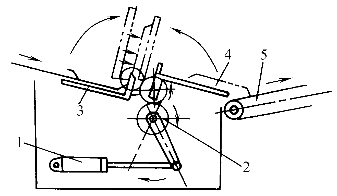 1—Cylinder 2—Gear 3—Flip Plate 4—Vacuum Suction Cup 5—Conveyor Belt | Use the flipper to turn the workpiece 180°, then send it to the next press via the conveyor and feeder. |
Figure 10 shows the BF type sheet metal destacking and feeding device manufactured by AP&T of Sweden, with sheet specifications of 180mm×300mm~
2500mm×3500mm, the maximum weight of a single blank is 50kg.
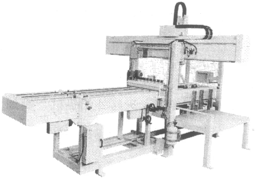
Figure 11 shows the pneumatic feeder produced by Herrblitz Modular System of Italy. The device uses compressed air for step feeding and can be integrated with uncoilers, levelers, and other equipment to form an automated coil material stamping feeding system, featuring good versatility and strong applicability.
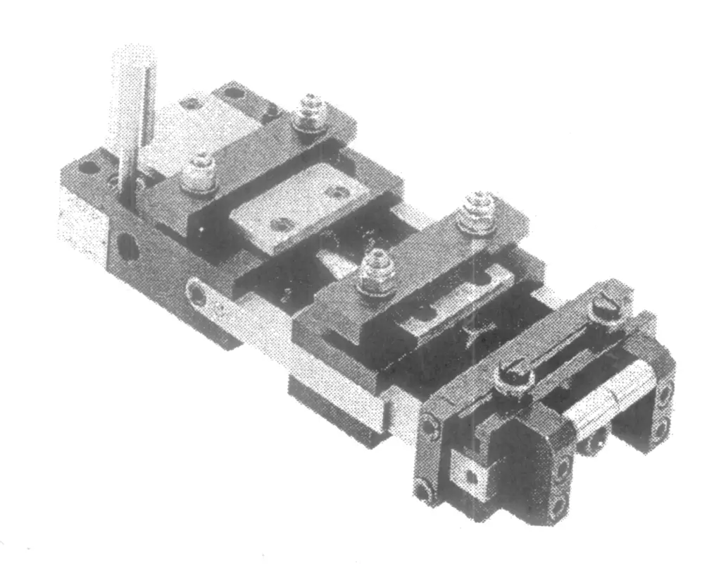
Depending on the type of feeding, pneumatic feeders are divided into push-type and pull-type. The difference is that in push-type feeders, the strip material is in a compressed state during feeding, suitable for occasions with good strip rigidity; while in pull-type feeders, the strip material is in a tensile state during feeding, suitable for feeding materials with poor rigidity and non-metals. The working cycle of pneumatic feeders is generally not high, only suitable for medium and low-speed automated stamping systems.
Figure 12 shows the LF series uncoiling, leveling, and feeding integrated machine manufactured by AIDA Engineering Technology Co., Ltd. of Japan, suitable for automated feeding with a production cycle of up to 120 times/min, featuring a compact structure and space-saving characteristics. Figure 13 shows a multi-station press production line composed of uncoiling, leveling, and feeding systems (product of Müller Weingarten AG, Germany).
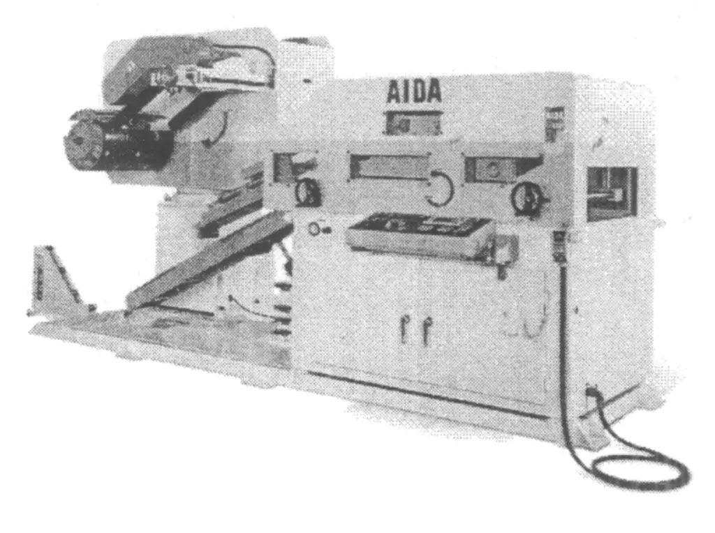
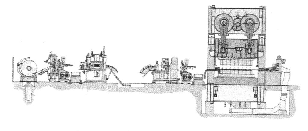
Figure 14 shows an automated stamping production line consisting of 4 medium-sized hydraulic presses, CD type loading and unloading robotic arms, and a rapid mold changing system (product of Sweden’s AP&T company).
IV. Stamping Flexible Manufacturing System FMS
With the increasingly fierce competition in the manufacturing market, the product renewal cycle is getting shorter, and the proportion of multi-variety, small-batch production in stamping is increasing, thereby strongly promoting technological progress in the field of stamping flexible manufacturing systems FMS (Flexible Manufacturing System).
The stamping flexible manufacturing system is an automated stamping processing system composed of a group of CNC forging machines, auxiliary machines, an automatic material storage and transportation system, and an information control system, managed by a computer to operate automatically. This system can process a set of stamping parts with different sequences and processing beats.
The process flow can be adjusted according to the different workpieces, can timely balance the use of resources, and thus this type of system can automatically adapt to changes in workpieces and production scale within the technical performance range of the equipment, achieving good economic benefits in single-piece small-batch, multi-variety production.
1. Basic Types
(1) Single Machine Stamping Flexible Processing
Using CNC press machines and CNC loading and unloading devices, or equipping ordinary presses with CNC automatic feeding devices, can automatically complete the flexible processing of various stamping parts. The CNC automatic feeding mechanism shown in Figure 15 is driven by two stepper motors, which drive the precision ball screw transmission, allowing the worktable to move freely in the x-y coordinate plane, suitable for stamping holes arranged in any pattern on various flat workpieces.
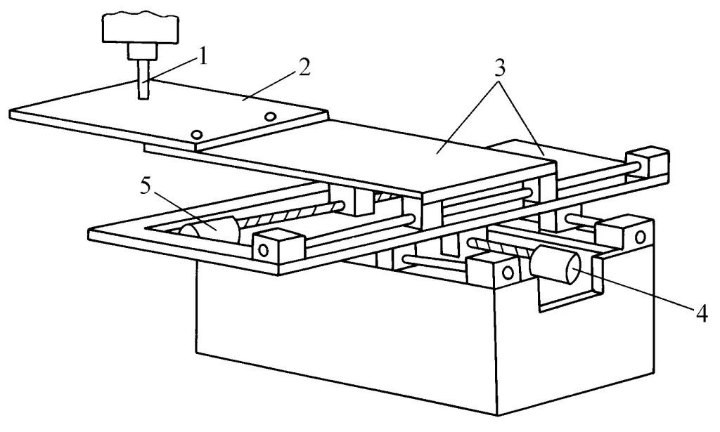
1—Punch
2—Blank
3—Slide
4—x-direction stepper motor
5—y-direction stepper motor
(2) Stamping Flexible Manufacturing Cell FMC
The Stamping Flexible Manufacturing Cell FMC (Flexible Manufacturing Cell) consists of a single CNC stamping machine, automatic loading and unloading devices, a sheet metal warehouse, and a computer control system, capable of automatically completing the entire stamping process. Figure 16 shows the stamping flexible manufacturing cell mainly composed of a CNC die rotating head press.
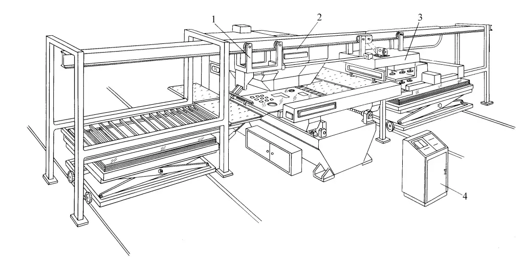
1—Clamp-type unloading device
2—CNC turret punch press
3—Suction cup type feeding device
4—Controller
(3) Flexible Manufacturing System for Stamping FMS
The flexible manufacturing system for stamping consists of three main parts: multiple CNC stamping machines forming an automated stamping system, a sheet metal transport and storage system, and a computer management control system. It can automatically complete the entire process of design and manufacturing technology, raw material transport, stamping processing, and workpiece output, characterized by high productivity, short auxiliary time for changing product types, and adaptability to various types of stamping processing.
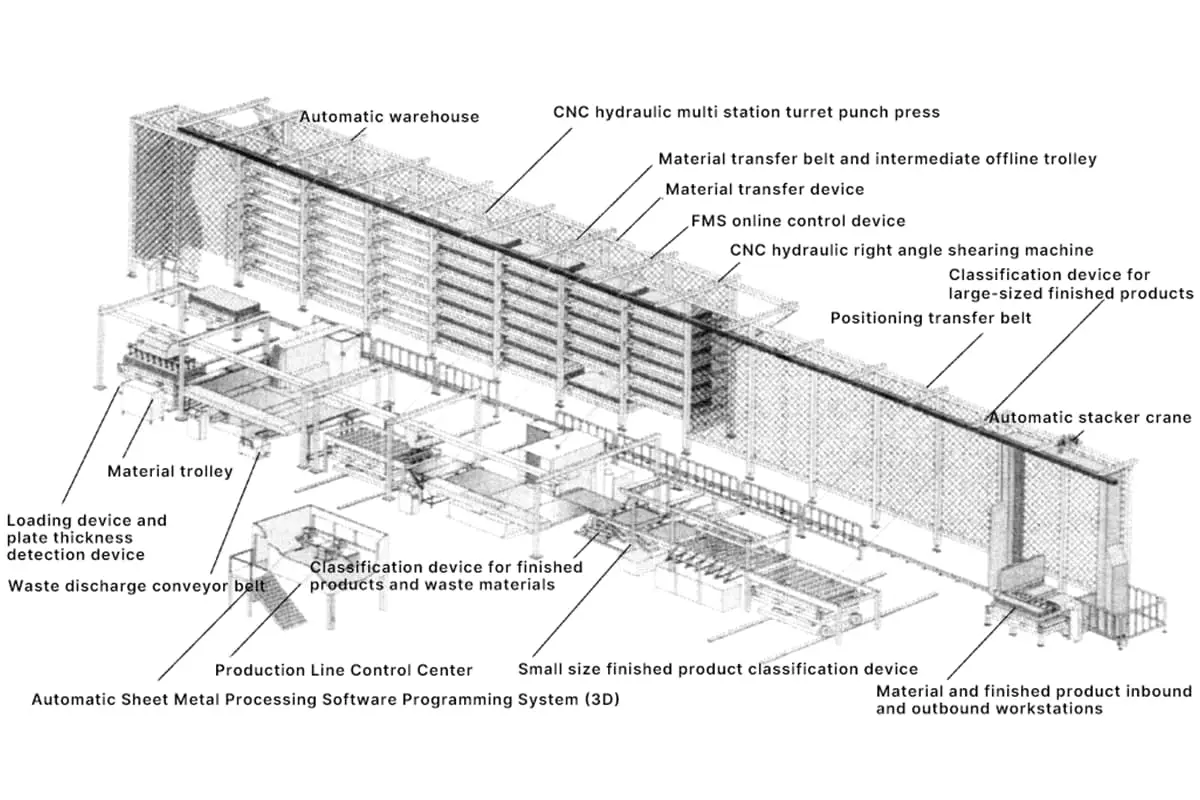
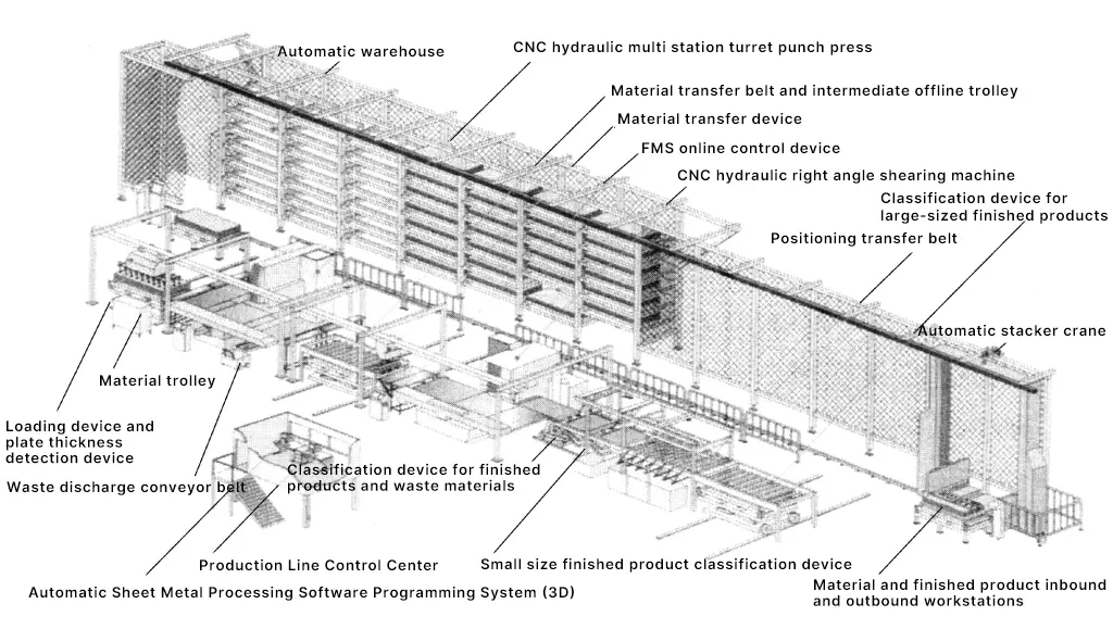
Figure 17 shows the layout diagram of the flexible manufacturing system for stamping. Figure 18 shows the FMS fully automatic stamping flexible manufacturing production line designed and manufactured by Murata Machinery Co., Ltd. of Japan, integrating CNC punch presses, right-angle shearing machines, automatic dispensing devices, and a comprehensive three-dimensional warehouse, capable of performing punching, shearing, and bending of sheet metal, achieving multi-variety, small-batch stamping production.
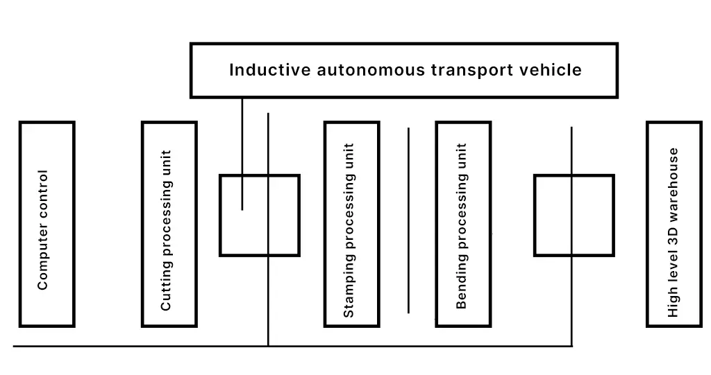
The CI-type flexible manufacturing system manufactured by Jinan Jiemai CNC Company consists of a PS31250 type CNC punch and shear compound machine, a sheet metal three-dimensional warehouse, a suction cup type feeder, a stacking and sorting device, and a control system, with blank sizes of 1250mm x 5000mm and a productivity of 8 sheets/h. The APSS-type flexible manufacturing system manufactured by Jiangsu Jin Fangyuan Company consists of a punch and shear compound machine, a positioning table, and an automatic loading robotic arm.
2. Main Equipment
(1) CNC Punching Equipment
The numerically controlled transformation of punching equipment is the foundation for realizing flexible punching processing systems. Commonly used CNC punching equipment in flexible punching processing systems includes CNC presses, CNC turret head presses, CNC right-angle shearing machines, CNC bending machines, CNC pipe bending machines, CNC laser cutting machines, CNC plasma cutting machines, CNC ultra-high pressure water jet cutting machines, etc.
(2) Automated System for Sheet Metal Transport and Storage
Basic forms of sheet metal transport devices include: stacking cranes, rail carts, rail-less carts, roller conveyors, etc. The main storage devices for sheet metal are automated sheet metal warehouses, which include high-bay automated warehouses and small box-type sheet frames.
High-bay automated warehouses are large to medium-sized warehouses, consisting of racks, stacker cranes, transport vehicles, pallets, and a computer control system. Under computer control, the stacker crane can accurately stop at the predetermined storage slot, and the pallet is the basic unit for accessing sheet metal.
During storage, the pallet with sheet metal is grabbed by a robotic arm and placed on the transport vehicle. After the transport vehicle enters the warehouse aisle, the stacker crane retrieves the pallet from the storage slot and hands it over to the transport vehicle, which then delivers the pallet to the automatic feeding device next to the processing machine.
Small box-type sheet frames are peripheral equipment of FMC, typically having 6 to 7 storage slots. Depending on processing needs, different sizes of sheet metal are stored in the frame. The storage and retrieval process is also computer-controlled.
(3) Rapid Mold Change System
The mold automatic warehouse is equipped with automatic mold identification and retrieval functions, and together with a mobile workbench and rapid clamping devices, forms a rapid mold change system. The mold clamping device uses electrical and hydraulic control, and the clamping process should be quick and reliable, with work parameters automatically adjustable.
(4) Computer Management Control System
The computer management control system of the stamping flexible processing system is divided into the following 3 levels.
The first level is the design management level, consisting of sheet metal planning and management and CAD/CAM. The sheet metal planning and management system controls inventory and mold information. It provides the DNC (Direct Numerical Control) system with the sequence of material feeding, inventory of sheet metal, and a list of molds.
The task of the CAD/CAM system is to automatically complete the design of individual pieces or nesting. During the design process, processes are established and process data is provided. The workpiece diagram after design is displayed on the screen for modification and inspection, and the relevant design information is sent to the DNC system as a basis for production.
The second level is the control level, namely the DNC system. After receiving the processing information provided by the previous level, this system begins system design. System design includes arranging business files, controlling business files to take effect in priority order, and controlling subordinate systems.
The third level is the execution work level, namely the parts below the DNC in the diagram, which are the executing mechanisms during the processing process, including CNC machine tools and peripheral equipment, such as CNC presses, CNC shearing machines, CNC automatic warehouses, etc.
V. Molds on the Automated Stamping Production Line
The design and manufacture of molds used on automated stamping production lines must follow the principle of no interference to ensure that the molds do not interfere with the feeding mechanism. Compared to traditional manual stamping molds and automatic punching molds, the molds used on automated stamping production lines differ greatly in structure, performance, and function, specifically reflected in the following aspects.
1. Molds used on automated stamping lines should be equipped with auxiliary positioning devices to ensure that the workpieces are correctly positioned in the mold.
2. To avoid the guide posts of the mold obstructing the loading and unloading of workpieces, the guide posts should be installed on the upper mold as much as possible.
Sensors should be installed inside the mold and connected to the electrical control system to detect whether the workpiece is correctly placed in the mold or whether the scrap has been smoothly removed.
During multi-station stamping, the molds at each station should maintain the same feed height as much as possible.
A reliable scrap removal device should be installed to ensure that scrap can be automatically and smoothly ejected from the mold.
The workpiece remains inside the lower mold, and under the action of the ejector device, it leaves the mold surface by about 5mm.
A centralized lubrication system and electrical junction box should be installed.
The mold should have multiple installation methods to accommodate different requirements for mechanical clamping and hydraulic rapid clamping.

