1. Crack
(1) Cracks caused by overburning on the surface These cracks are mostly distributed on the corner edges of the connecting rod forgings, especially in areas subjected to tensile stress during forging. The characteristics are that the cracks are short and thick, irregularly densely distributed on the surface of the forging, and extend inward along the grain boundaries; the inside of the cracks is filled with oxides, severe decarburization on both sides, coarse grains, and the presence of Widmanstätten structure.
(2) Cracks caused by too low temperature during final forging or sizing These cracks are mostly distributed in areas of the forging that are subjected to tensile stress during die forging or at the boundaries of metal flow. They are characterized by being deep, long, and relatively dense.
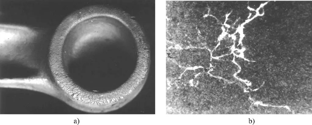
(3) Cracking (see Figure 6-32) The characteristic is that the cracks are relatively shallow and net-like distributed on the surface of the forging. The main reasons for their formation are as follows:

a) Cracking at the small end of the connecting rod b) Copper in steel
1) Copper, tin segregation in the raw material, or excessive content of copper, tin. Because copper and tin have low melting points, they melt during forging heating, causing localized plasticity to decrease and cracks to form.
2) Excessive sulfur content in the fuel, especially when using gas or natural gas as fuel, due to incomplete desulfurization, sulfur penetrates the surface layer of the billet along the grain boundaries during heating, forming sulfide inclusions at the grain boundaries, weakening the connection between grains, leading to cracking during die forging.
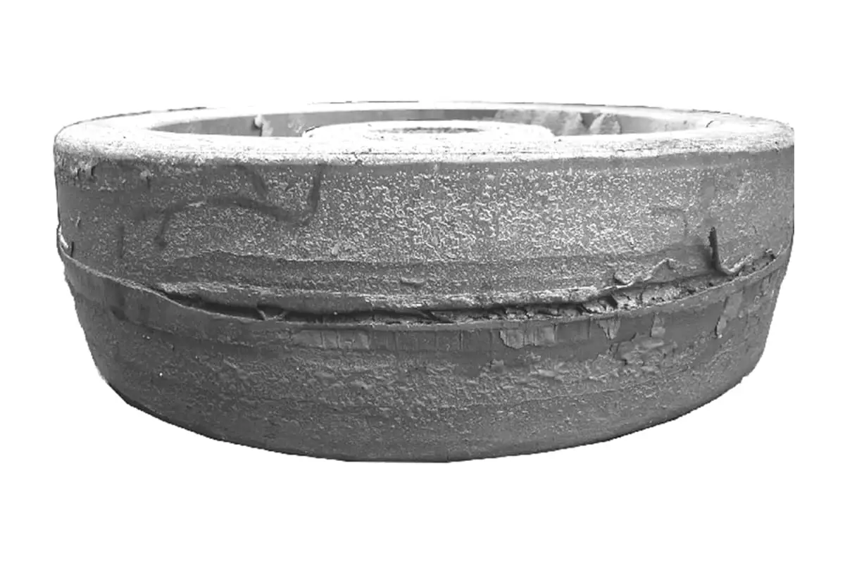
(4) Longitudinal cracks along the parting line (see Figure 6-33) These cracks are caused by non-metallic inclusions. Due to non-metallic impurities such as sulfur and phosphorus in steel, as well as defects such as shrinkage and porosity that were not welded during billet making or forging, they are squeezed into the flash during die forging, and cracks appear at the parting line during trimming.

1) Billets with severe defects, defects are squeezed to the flash, appearing as cracks along the cut surface of the flash, or the forging is split into two halves along the parting line of the forging die (see Figure 6-34). Due to the presence of shrinkage or porosity in the steel ingot, which is elongated during drawing or roll forging, the edges of the shrinkage or porosity squeezed out during die forging are pressed into the flash, and these defects are revealed after trimming the flash.

a) Billet defects b) Defects squeezed to the flash
2) The reason for the formation of cracks during the forging process is the different surface roughness of the upper and lower bridges of the flash groove, which causes different resistance when the metal flows into the flash groove, resulting in easy generation of shear stress within the parting surface,
causing the parting surface to delaminate and crack.
3) Severe misalignment during die forging, causing the parting surface to tear during the trimming process (see Figure 6-35).

The parting surface is torn during the process
2. Scale forged into the forging
In addition to changing the cross-section and length dimensions of the billet and distributing metal, the upsetting step in hammer die forging also serves to remove scale. If the upsetting step is not operated according to process requirements, and the scale is not completely removed, it will be pressed into the forging during final forging. After the scale falls off the forging, pits are formed on the surface, leaving black scale on the machined surface. Traces left after pickling and knocking off the scale of the forging can be as deep as 3mm.
If this defect exceeds the machining allowance, it may cause the forging to be scrapped. Therefore, it is important to carefully remove the scale to avoid the occurrence of this defect.
The main reasons for this quality defect are as follows:
1) Forging defects such as indentations caused by uncleaned oxide scale in the die grooves during forging. Especially at the front and back ends of the die grooves, a slight negligence can lead to dead angles in blowing.
2) Severe oxidation during billet heating, where the oxide scale cannot be completely peeled off during pre-forging, causing indentations on the forging due to parts of the oxide scale sticking to the billet. To fundamentally solve this, it is necessary to strictly control the heating quality. If this oxide scale is forged onto the forging, it will form pits and cavities on the surface, or reduce the size of the working cross-section of the part.
3) Die jumping during the forging process, causing secondary introduction of oxide scale into the final forging die and resulting in indentations on the forging. Therefore, it is essential to clean the oxide scale from the die grooves after die jumping before continuing with forging.
4) Slag formation at the bottom of the furnace, where the oxide scale adheres strongly to the metal, making it impossible to shake off during die forging and not cleanable during pickling. Even if this type of oxide scale can be removed from the forging, the dimensions of the forging often shrink.
3. Denting
The characteristic of this type of scrap is mechanical damage. Mechanical damage occurs to the forging when it is removed from the forging die grooves or during the handling of hot forgings; or during trimming, when unrelated objects (such as perforated thin sheets) fall onto the trimming die causing mechanical damage to the forging. If the depth exceeds the machining allowance, the forging is scrapped.
4. Damaged forging
The forging is damaged by impact before it is securely placed in the lower die groove or while moving within the die groove. The reasons for this type of scrap are as follows:
1) The operator did not correctly place the blank in the final forging die or on the trimming die, or the forging was impacted when it jumped out of the die groove.
2) The forging hammer has overlapping impact phenomena, i.e., stepping on the pedal once causes the hammer to strike multiple times, and processing is also carried out on faulty forging dies and trimming dies.
3) During trimming, if the forging is not placed inside the die, it will also damage the forging. The damage to the forging is mainly caused by the operator’s carelessness, and the only way to prevent damage to the forging is to operate carefully.
5. Incorrect streamline
Normally, the streamline distribution of a forging is consistent with the shape of the forging, as shown in Figure 6-36.
However, if the pre-forging die groove is designed unreasonably, the worker operates improperly, or due to die wear, improper billet upsetting methods, or misplacement of the billet in the die groove, it can cause uneven metal flow, potentially resulting in disordered and turbulent streamlines.
Disordered streamlines can lead to varying degrees of decline in various mechanical performance indicators. Therefore, for important forgings, there are requirements for streamline distribution.

Eddy currents, through-flow, and rib penetration defects are caused by the same reasons as folding, all due to unreasonable metal distribution on the billet cross-section or the billet volume exceeding the forging by a lot, causing severe uneven metal flow during the filling of the die groove. Looking at the shapes of forgings that are prone to these three defects, most occur in forgings with “L”, “Π”, or “T” shaped cross-sections.
Although these three defects are caused by uneven metal flow, the degree of unevenness varies, leading to different consequences; lighter cases form eddy currents (see Figure 6-37), more severe cases form through-flow (see Figure 6-38), and the most severe cases cause rib penetration cracks.
Eddy currents and through-flow often accompany coarse grain phenomena, which is due to the severe flowing metal tending to aggregate and recrystallize. Experimental results show that eddy currents and through-flow have little impact on part strength, but have a significant impact on plasticity, and the most severe impact on fatigue performance and corrosion resistance.


6. Forging deformation
Deformation refers to the deviation of the forging’s centerline and plane from the correct shape on the forging diagram. This defect can occur during die forging, punching trimming, transportation, or heat treatment. The deformation produced in these cases can be remedied by correction methods. There are correction processes in the subsequent processes of the forging, such as correction in the forging die, on a hydraulic press, by embossing, or manually.
(1) Deformation caused by demolding can be illustrated by comparing it to the process of removing a casting from a mold. The demolding of a casting can be achieved by destroying the sand mold, whereas the demolding of a forging must be done similarly to how a wooden pattern is removed from a sand mold during casting, by extracting the forged piece from the mold cavity.
Therefore, to facilitate the demolding of forgings, it is necessary to apply the principle of “sand removal dimension” — the taper for sand removal, to all mold walls that are perpendicular to the direction of forging pressure, creating a certain angle of slope, known as the forging draft angle (typically between 5° and 12°).
Otherwise, the soft forged piece, squeezed into the mold cavity, can only be forcibly pulled out with pliers, which would deform the already forged piece.
Some forging dies are poorly designed, requiring the use of a sharp tool to pry out the forged pieces, inevitably causing deformation. A better approach is to pay attention to the die taper and to minimize the depth of the mold cavity (the vertical space above and below the parting surface) relative to its width, and ideally less than its length, to allow the forged piece to jump out automatically or be removed with minimal effort.
(2) Deformation caused by punching or trimming Due to inaccurate trimming punches or poor die design, complex trimming profiles with thin cross-sections can warp, and long forgings often become bent due to trimming deformation.
(3) Deformation caused by post-forging cooling or heat treatment Uneven cooling after forging or improper heating and cooling methods during heat treatment can cause deformation. Common deformations include bending of long-axis forgings, which can be corrected by straightening.
For medium and low carbon steel and low alloy structural steel forgings, if the bending is less than 10mm, it can be corrected cold; large deformations in forged steel or various alloy tool steels, medium carbon alloy structural steel forgings should be corrected hot, or annealed after straightening to relieve stress.

