Bench Worker’s Handbook: Tools and Techniques
Have you ever wondered what tools and techniques skilled bench workers use to craft precision parts? From workbenches to grinding…
Production equipment is the tool for assembly fitters’ work. Knowing how to use and maintain it can ensure effective utilization and extend its service life, while also preventing personal injury and equipment accidents.
This chapter starts with the operating procedures of common equipment used by assembly fitters. It first introduces the operation and use of drill presses, power tools, grinding machines, cranes, and other tools and equipment. These are fundamental content that should be mastered proficiently. Then it introduces the structure, use, and maintenance of common equipment for assembly fitters, which requires trainees to master in practice. With the continuous development of science and technology, the advancement and automation level of equipment will greatly improve, and the standards for equipment maintenance will also change.
Training Objective: Master the operating procedures for common equipment used by assembly fitters.
1) It is strictly forbidden to wear gloves when drilling. Sleeves should be tied tightly, and female workers should wear work caps. Operators should not hold cotton yarn or other textile or woven materials in their hands to prevent accidents caused by chips or drill bits accidentally hooking onto them.
2) Do not use hands or rags to remove chips during drilling, and do not blow them away with your mouth. A brush must be used to remove chips. For strip-shaped chips, use a hook to break them or cut them off promptly, and try to remove them when the machine is stopped.
3) During operation, the operator’s head should not be too close to the rotating spindle to avoid danger. When stopping, let the spindle stop naturally, do not brake with your hand, and do not use reverse rotation to brake.
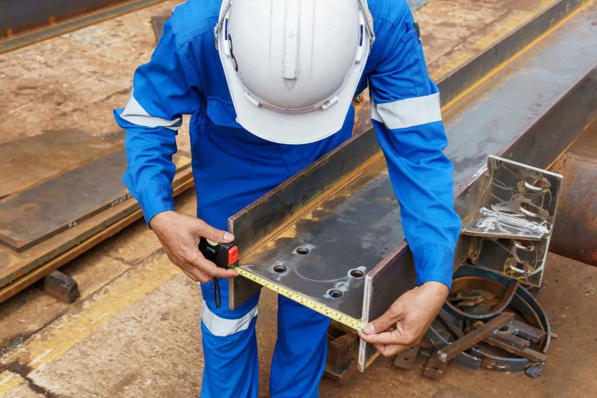
4) When drilling, the workpiece must be firmly clamped, especially when drilling large diameter holes in smaller workpieces. The clamping must be secure.
5) The drill bit should be sharp, and the feed force should be appropriate when drilling. Especially when drilling through-holes, reduce the feed force when the hole is about to be drilled through to prevent accidents such as the workpiece being thrown out due to a sudden increase in feed.
6) It is strictly forbidden to install or remove workpieces while the machine is running. Inspecting workpieces and changing spindle speeds should be done when the machine is stopped.
7) The power must be disconnected when cleaning the drill press or adding lubricating oil.
8) Adjusting the feed rate must be done when the machine is stopped. For automatic feeding, adjust the feed rate according to the drill bit diameter and workpiece material type, and fix the travel limit block.
9) The operator is strictly prohibited from leaving while the drill press is working, especially when using powered feed, to prevent equipment accidents caused by exceeding the travel limit.
10) When removing the drill bit transition taper sleeve, use a standard wedge. It is strictly forbidden to use hammers, iron rods, or other improper tools to pry, to prevent damage to the spindle.
11) When using a radial drill press, the drill bit must be kept away from the workpiece and worktable when the arm is lowered. The operator should be focused and operate carefully to prevent equipment malfunctions or sliding that could lead to operational errors and damage to the equipment. Never raise or lower the spindle box while drilling.
12) When the drilling diameter approaches the maximum limit of the radial drill press, the workpiece should be clamped close to the column side and should be worked on in a clamped state.
1) When drilling holes in thin plates or smaller workpieces with a diameter exceeding 8mm, a bench vise or small machine vise must be used to hold the workpiece. Do not directly hold the workpiece by hand for drilling (Figure 1a).
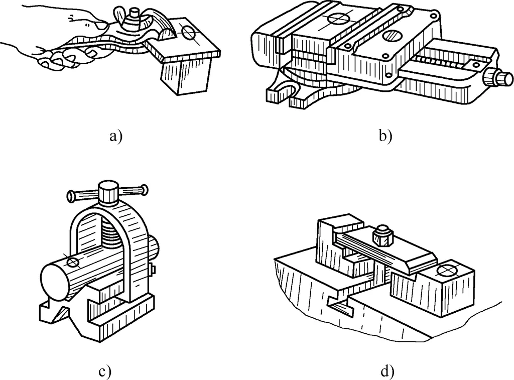
2) When drilling holes in longer workpieces, although they can be held by hand, it is better to add fixed screws on the drill press worktable to support the workpiece, which is safer and more reliable.
3) When drilling holes in flat workpieces, generally clamp the workpiece in a machine vise (Figure 1b). When clamping, ensure that the workpiece surface is perpendicular to the drill bit. If the drilling diameter is relatively large, the machine vise should be fixed to the drill press worktable with bolts and pressure plates. When using a machine vise to clamp workpieces for through-hole drilling, place a spacer under the workpiece to leave space for the drilling area to avoid damaging the machine vise.
4) When drilling holes in cylindrical workpieces, place the workpiece on a V-block (Figure 1c) to prevent the workpiece from rotating. When clamping, ensure that the drill bit centerline coincides with the symmetrical plane of the two inclined surfaces of the V-block to ensure that the center line of the drilled hole passes through the axis of the workpiece.
5) For large holes or workpieces that are inconvenient to clamp with a machine vise, use pressure plates, bolts, and spacers to fix them to the drill press worktable (Figure 1d). Pay attention to the following:
① The spacers should be as close to the workpiece as possible to reduce the bending deformation of the pressure plate.
② The spacers should be slightly higher than the clamped surface of the workpiece, but not lower than it. Otherwise, when the workpiece is clamped, the pressure point between the pressure plate and the workpiece will be at the edge of the workpiece. When only one pressure plate is used to clamp the workpiece, the workpiece will lift. When the spacer is slightly higher, even if the pressure plate bends slightly, it can still ensure that the pressure point is not at the edge of the workpiece, preventing the workpiece from lifting.
③ The bolts should be as close to the workpiece as possible, which can provide greater clamping force on the workpiece and avoid movement of the workpiece during the clamping process.
④ If the clamping surface of the workpiece has been precision machined, copper foil or similar material should be used as a cushion to prevent indentations from the pressure plate. It is strictly forbidden to use fabric or other textile or woven materials as cushions on machined surfaces to prevent accidents caused by chips hooking onto them.
Straight shank drill bits are held by drill chucks, with a clamping length of no less than 15mm, otherwise, the drill bit may become misaligned or fall out due to torsional forces during drilling. Taper shank drill bits are directly connected to the drill press spindle sleeve using the Morse taper on the shank. When connecting, the drill bit taper shank and spindle taper hole must be cleaned, and the flat tail of the taper shank should be aligned with the waist-shaped hole on the spindle. Use accelerated impact force to install in one go.
When the drill bit taper shank is smaller than the spindle taper hole, a transition sleeve can be used for connection. Ensure that the drill bit is firmly connected to the drill press spindle and that the radial runout (used for geometric tolerances) is minimal during rotation.
Before drilling, the center punch mark for the hole should not be too small, otherwise the drill bit’s chisel edge cannot initially fall into the conical hole of the center punch mark when starting to drill, and the drill bit will deviate from the center during drilling.
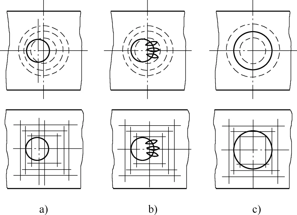
When starting to drill, first align the drill bit with the center of the hole to create a shallow conical pit, visually check the concentricity of the initial shallow conical pit with the scribed circle, and continuously make corrections. If the hole position is significantly offset, you can correct the center punch mark in the opposite direction or use a chisel to create several grooves in the shallow conical pit to reduce the cutting resistance in this area, allowing the drill bit to shift and achieve the correction purpose (Figure 2).
The correction process must be completed before the diameter of the initial conical pit becomes smaller than the drill bit diameter. This is an important step to ensure the accuracy of the hole position. If the diameter of the initial conical pit has already reached the hole diameter and the hole position is still offset, it will be difficult to correct at this point, leading to increased hole position error and affecting assembly accuracy.
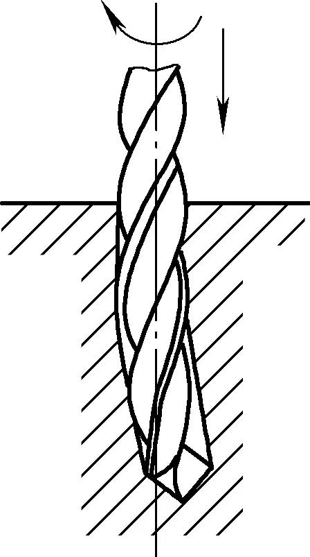
When using manual feed, the feed force should not be too large, otherwise it will cause the drill bit to bend and deform (especially prominent when drilling long, thin holes), leading to a skewed drill hole axis (Figure 3). A skewed drill hole axis will directly affect the shape, position accuracy, and assembly quality of the hole. It can also be dangerous, potentially causing drill bit breakage or workpiece ejection.
1) Choose the appropriate hand-held electric drill based on different hole diameters, and pay attention to protective grounding or protective zero connection.
2) Before using the hand-held electric drill, run it without load to check if the sound of the transmission parts and rotation direction are normal. When using the hand-held electric drill, apply force evenly and concentrate on controlling the pressure. The pressure should be appropriate, and maintain the drill bit axis perpendicular to the machining surface. Reduce pressure when about to drill through to prevent excessive force. When the drill bit suddenly encounters resistance, be careful of wrist injury due to the reaction force. Similar caution should be taken when restarting after the drill bit has stopped rotating in the hole.
3) Do not overload the hand-held electric drill. When the drill bit diameter is close to or equal to the maximum working capacity of the hand-held electric drill, the applied force should be appropriately reduced to prevent overload damage to the drill.
4) Do not use the hand-held electric drill as a substitute for an electric wrench to tighten bolts. Due to the high speed of hand-held electric drills, when a bolt is suddenly stopped after tightening, the reaction force can easily cause wrist injury.
5) Electric drills should be regularly cleaned of dust and oil, and ensure proper ventilation. Electric drills must not be used in flammable or explosive conditions, nor stored in damp environments or those with corrosive gases. Do not drag or throw electric drills carelessly to prevent damage.
6) New electric drills or those stored for a long time should have their insulation resistance tested before use. The resistance value must exceed 0.5MΩ; otherwise, they should undergo drying treatment.
1) It is forbidden to connect handheld power tool power cords without authorization. When electric tools are needed, an electrician should connect the wires and check if the metal casing is electrified. There should be a safety ground, preferably with a safety protection socket.
2) It is forbidden to use electric tools with damaged power cords. During use, care should be taken to protect the power cord. Dragging is prohibited, and heavy objects or wheels should be prevented from crushing the power cord, which could damage the insulation and cause electric shock or short circuit accidents.
3) It is forbidden to use electric tools without insulation protection measures. Especially when operating in relatively damp environments, it is important to wear insulating shoes, insulating gloves, and work on an insulating rubber mat or dry wooden board to prevent electric shock.
4) It is forbidden to use electric tools with shared neutral and ground wires. When the power cord is pulled or the neutral wire has poor contact, the metal surface of the electric tool will generate voltage, causing electric shock accidents.
The grinder is common equipment in the fitter’s workplace, consisting of an electric motor, grinder base, tool rest, and protective cover. It is mainly used for sharpening chisels, drill bits, scrapers, and other cutting tools, or for removing burrs, sharp edges, and hard surface layers from workpieces or materials.
Grinders are also equipment prone to safety accidents. The grinding wheel is brittle and rotates at high speeds. Therefore, when using a grinder, it is necessary to strictly follow the operating procedures to prevent safety accidents.
1) When using a grinder, before starting, carefully check for any foreign objects between the grinding wheel and the protective cover, and whether the grinding wheel has any impact marks or damage. Only start the grinder after confirming there are no issues. After starting the grinder, wait until the wheel rotates steadily before grinding. If the wheel wobbles noticeably, stop the machine immediately for adjustment.
2) The distance between the grinder’s tool rest and the grinding wheel should be maintained within 3mm to prevent workpieces from getting caught and causing accidents. If the gap is too large, it should be adjusted before use. When grinding workpieces or cutting tools, do not apply excessive force.
3) Do not grind soft metals like aluminum, copper, or wood on the grinder. Do not use the grinding wheel when it is worn beyond its limit.
4) When grinding, the operator should stand at the side or diagonal side of the grinder to avoid injury from wheel fragments in case of breakage.
5) Do not use substandard grinding wheels. When replacing grinding wheels, refer to the safety operation procedures for grinders. It is forbidden to use cracked or damaged grinding wheels.
6) When installing the grinding wheel, the clamping plates should not directly contact the wheel. Paper washers should be placed between the clamping plates and the wheel. The assembly should be circular and rotate smoothly.
7) Protective goggles must be worn when using a grinder.
1) Do not use handheld grinders without safety guards or proper grounding. Before use, carefully check the grinding wheel for impact damage and cracks, ensure the metal casing is not electrified, and verify the power cord is intact. If damaged, repair before use. Always perform a no-load test run before using a handheld grinder, and only use it after confirming the correct rotation direction.
2) When using a handheld grinder, full concentration is required. Before starting the grinder, firmly grip the grinder body. Avoid placing the wheel close to the ground or workpiece to prevent the grinder from rolling along the surface due to reaction force when started, which could cause the wheel to fly off and result in an accident.
Do not randomly place a rotating handheld grinder on the ground or workpiece. It must be placed in a designated safe place only after the wheel has completely stopped. When not in use temporarily, the power must be turned off.
3) Do not use the side of the grinding wheel to grind workpieces. When using a handheld grinder, use the face of the wheel, hold the grinder firmly, and slowly contact the workpiece. Impacts or sudden pressure are prohibited. It’s best if no one stands around during operation. The operator should not face the grinding wheel directly and must wear protective goggles and other necessary protective equipment.
4) Do not use grinding wheels with signs of damage. Handheld grinders without manual switches must not be used. Due to the high rotation speed and low strength of handheld grinder wheels, they are prone to breakage. When installing the grinding wheel, ensure proper fit and tighten the nut appropriately with a wrench.
5) Store handheld grinders in a dry place. Avoid storing them in damp areas or places where they might come into contact with water to prevent damage to internal insulation.
During the assembly process, fitters should use lifting equipment for heavier parts or components to reduce the operator’s physical strain, improve work efficiency, and ensure production safety.
Jacks are suitable for lifting heavy objects to limited heights and for moving heavy objects. Commonly used types include screw jacks, rack and pinion jacks, and hydraulic jacks. The following procedures should be followed when using jacks:
1) It is forbidden to use manual hoists with defective hooks, chains, brakes, or other potential hazards. When lifting workpieces or heavy objects with a manual hoist, the frame supporting the hoist must be secure and reliable.
2) It is forbidden to overload manual hoists or force them to lift heavy objects. Choose the appropriate manual hoist based on the size and weight of the object to be lifted.
3) It is forbidden to suspend heavy objects in mid-air for extended periods. People are prohibited from passing under or lingering beneath suspended loads. When lifting objects, they must be securely fastened. Ropes should be used within their allowable load range. When ropes pass over relatively sharp edges, soft material should be used as padding to prevent excessive wear and breakage of the rope. When using two or more hoists to lift the same object simultaneously, a designated person must coordinate. Lifting or lowering should be done slowly.
4) When lifting heavy objects, it is strictly forbidden to rush the lifting. First check if the binding is secure and if the center of gravity is properly positioned. Then lift 0.5m and proceed with lifting only after inspection confirms it is safe.
5) When installing equipment, it should be lifted reasonably. Choose the length and thickness of ropes according to the equipment’s weight. First lift about 0.5m to test the center of gravity of the heavy object, then proceed with lifting after confirmation. Improper lifting is strictly prohibited to avoid equipment deformation and affecting precision.
6) It is forbidden to use wire ropes that exceed the wear standard. Wire ropes with broken wires exceeding regulations or damaged joints are also prohibited from use.
7) Wire ropes in use are prohibited from contacting live metal (including electric wires, welding machine cables, etc.) to avoid burning or reducing the strength of the wire rope due to heat.
8) It is forbidden to lift objects beyond the capacity of the wire rope. The diameter of the wire rope must be reasonably chosen according to the weight of the object being lifted.
9) When using a winch, place it on a flat surface free of obstacles. Use secure ground anchors or pile anchors to hold it in place. The fixing must be reliable to prevent the frame from moving or tilting under force.
10) When using a winch, the running rope should be horizontally guided towards the guide pulley, not directly to a high position.
11) When using a winch, one end of the running rope should be pulled out from the top of the drum core and tightened by an experienced person. The rope should generally wrap around the drum core 4 to 6 turns.
12) During lifting operations, the horizontal angle between the sling and the object should preferably be above 45°. If the horizontal angle is too small, the height of the sling can be lowered, but the horizontal force on the sling or equipment will increase. Excessive force can easily cause machine deformation and damage when the strength is weak.
Training Objective: To be able to correctly use common fitter’s equipment and perform maintenance and care.
A drilling machine is a common hole-processing machine tool. By installing drill bits, reamers, counterbores, reamers, boring tools, taps, and other tools on the drilling machine, operations such as drilling, reaming, counterboring, reaming, boring, and thread tapping can be performed. Drilling machines are one of the most commonly used machine tools for assembly fitters.
Drilling machines can be classified into three types based on their structure and application range: bench drilling machines (abbreviated as bench drills), upright drilling machines (abbreviated as upright drills), and radial drilling machines (abbreviated as radial drills).
A bench drill is a small drilling machine that can be used on a workbench, with a maximum drilling diameter generally up to 12mm. The lowest spindle speed of a bench drill is relatively high, generally not lower than 400r/min, so it is not suitable for counterboring, reaming, and thread tapping. Bench drills usually use V-belt transmission, with a five-step tapered pulley to change speeds.
The spindle feed of a bench drill is only manual, and it usually has devices to control drilling depth, such as graduated dials, graduated rulers, or fixed-travel devices. After drilling, the spindle can automatically return to its original position under the action of a spiral spring.
1) Structure of a Bench Drilling Machine
The Z512 bench drill is a simple structure commonly used by assembly fitters, as shown in Figure 4.
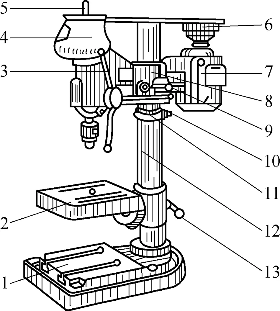
1—Base
2—Worktable
3—Feed handle
4—Cover
5—Spindle
6—Pulley
7—Motor
8—Body
9—Handle
10—Screw
11—Safety ring
12—Column
13—Worktable locking handle
The motor 7 drives the spindle 5 through the pulley 6 and V-belt to achieve several different rotation speeds. The body 8 is fitted on the column 12 for up and down movement and can be rotated to any position around the column center. After adjusting to the appropriate position, it can be locked with handle 9. If the body needs to be lowered, first adjust the safety ring 11 to the appropriate position and lock it with screw 10, then slightly loosen the handle to let the body fall onto the safety ring by its own weight, and then lock handle 9.
When the worktable locking handle 13 is loosened, the worktable 2 can also move up and down on the column 12 or rotate to any position around the column center. When drilling holes in small workpieces, the workpiece can be placed on the worktable; for larger or taller workpieces, the worktable can be rotated away and fixed, and the workpiece can be placed directly on the drill base 1 for drilling.
2) Operation of a Bench Drilling Machine
① Adjustment of spindle speed.
Choose an appropriate speed based on the drill bit diameter and the material being processed. Speed adjustment is achieved through a set of tapered pulleys inside the upper cover 4 of the bench drill. When adjusting, the spindle should be stopped. Open the cover, manually rotate the pulley, first hang the V-belt on the smaller pulley, then on the larger pulley, gradually hanging the V-belt on the appropriate pulley until the desired speed is achieved.
② Adjustment of the worktable’s up-down and left-right position.
Hold the worktable with your left hand, loosen the worktable locking handle 13 with your right hand, swing the worktable 2 to move it down or up to the desired position, then lock the worktable locking handle 13 again.
③ Adjustment of the spindle feed position.
Spindle feed is achieved by rotating the feed handle 3. The spindle extension should not be too long, so before drilling, first test-raise and lower the spindle to check if the workpiece placement height is appropriate (adjust using the worktable elevation).
3) Correct Use and Maintenance of Bench Drilling Machines
① When drilling, the workpiece should be clamped with a pressure plate (except when drilling small holes in larger workpieces, which can be held by hand). When the through-hole is about to be drilled through, reduce the feed force to prevent accidents such as drill bit sticking or workpiece flying out.
② During drilling, tools, measuring instruments, and other items should not be placed on the worktable surface. When drilling through-holes, ensure that the drill bit can pass through the relief hole (or T-slot) on the worktable surface, or place a spacer block under the workpiece to avoid damaging the worktable surface.
③ The worktable surface should be kept clean regularly. After use, the exposed sliding surfaces of the bench drill and the worktable surface must be wiped clean, and lubricating oil should be added to all sliding surfaces and oil holes.
Upright drilling machines have maximum drilling diameters of ϕ25mm, ϕ35mm, ϕ40mm, and ϕ50mm, among other specifications. Upright drilling machines can achieve automatic feed. Both spindle speed and automatic feed rate have a wide range of adjustments, making them suitable for drilling, reaming, counterboring, reaming, and thread tapping of various medium-sized workpieces. Due to its higher power and more complete mechanism, it can achieve higher efficiency and processing accuracy.
1) Structure and Performance of Z535 Upright Drilling Machine
The Z535 upright drilling machine is a type of drilling machine commonly used by assembly fitters, as shown in Figure 5a.
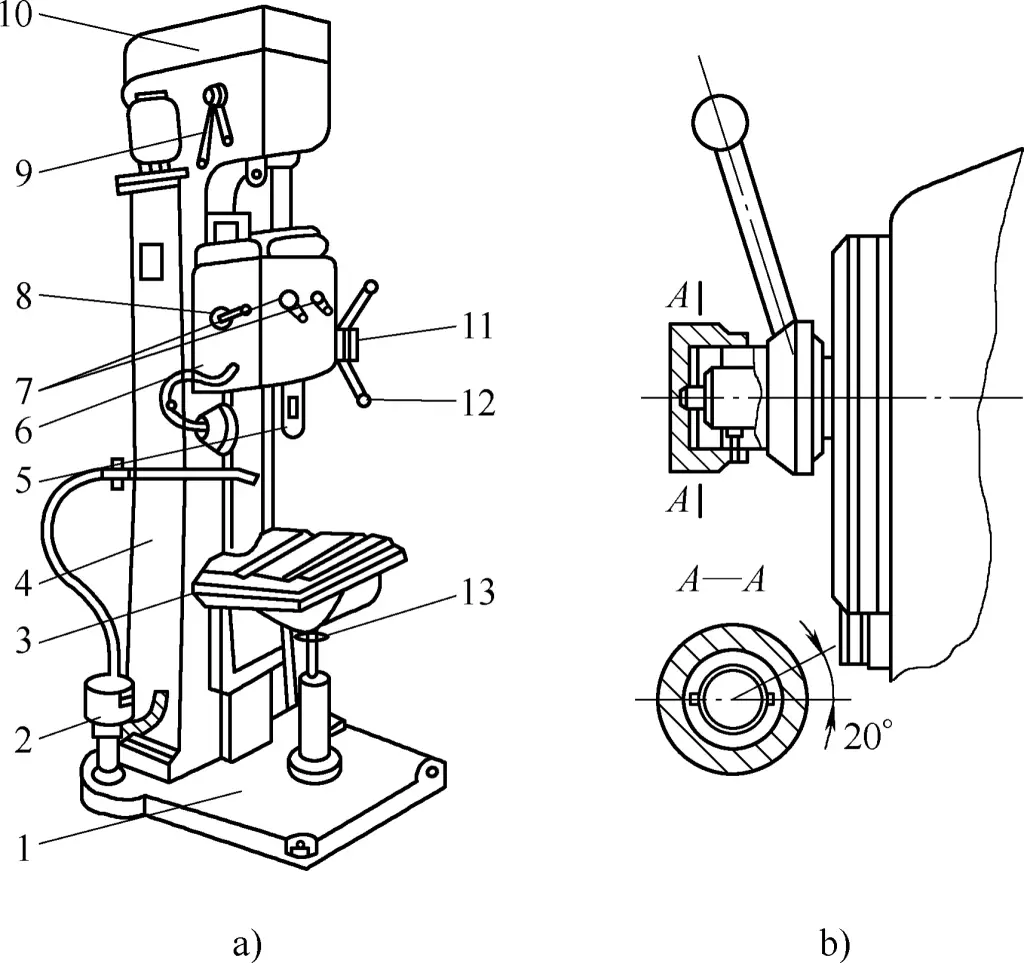
1—Base
2—Hydraulic pump
3—Worktable
4—Column
5—Spindle
6—Feed box
7—Feed handle
8—Forward/reverse handle
9—Speed change handle
10—Spindle box
11—End cover
12—Operating handle
13—Worktable elevation handle
The bed 4 is fixed on the base 1. The spindle box 10 is fixed on top of the bed. The feed box 6 is installed on the vertical guide rail of the bed and can move up and down along it. For ease of operation, a counterweight balancing the spindle’s self-weight is installed inside the bed. The worktable 3 is installed on the lower part of the bed’s vertical guide rail and can also move up and down along it to accommodate workpieces of different heights.
The Z535 vertical drilling machine is also equipped with a cooling device. The cutting fluid is stored in the cavity of the base and is discharged by the hydraulic pump 2 when in use.
The main performance and specifications of the Z535 vertical drilling machine are as follows:
Maximum drilling diameter ϕ35mm
Spindle hole taper Morse No. 4
Spindle travel 225mm
Spindle speed 68~1000 r/min
Feed rate 0.11~1.6mm/r
Worktable travel 325mm
Motor power 4.5kW
2) Operation of vertical drilling machine
① Adjustment of spindle speed.
Determine the spindle speed based on the drill bit diameter and workpiece material. Speed change is achieved through the speed change lever 9. The forward/reverse lever 8 is used to control the forward rotation, reverse rotation, or stopping of the spindle 5.
② Adjustment of the worktable lifting device.
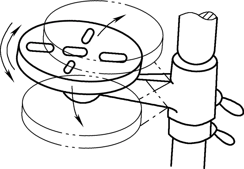
According to the height of the drilling position on the workpiece, adjust the worktable up and down along the vertical guide rail on the bed using the worktable lifting handle 13 installed under the worktable. There is also a type with a cylindrical bed where the worktable is cylindrical and can rotate around its axis while also rotating around the bed, as shown in Figure 6, making it easier to align the drilling position of the workpiece.
③ Adjustment of spindle feed.
The spindle feed has two types: automatic feed and manual feed.
For automatic feed, first set the two feed handles 7 to the desired position to determine the required feed rate, then pull the end cap 11 outward and rotate it 20° clockwise relative to the handle, as shown in Figure 5b, to put it in the automatic feed position. When the spindle rotates, automatic feed can be achieved. For manual feed, rotate the end cap 20° counterclockwise relative to the handle and push it back to its original position, at which point the automatic feed device disengages.
For manual feed, rotate the end cap 20° counterclockwise relative to the handle and push it back to its original position, at which point the automatic feed device disengages. Turn the operating handle 12 counterclockwise for feeding and clockwise for retracting.
When tapping threads, the handle must be placed in the manual feed position. First, use manual feed to make the tap cut in. After the tap has cut in 2-3 turns, you can stop using manual feed and apply axial pressure, relying on the thread of the tap itself to drive the spindle feed. After tapping is complete, you can reverse the spindle to retract the tap.
3) Rules for using vertical drilling machines
4) Maintenance of vertical drilling machines
Proper maintenance of machine equipment plays a very important role in reducing equipment failures and extending the service life of machines. Machine maintenance implements a “three-level maintenance system,” namely daily maintenance, first-level maintenance, and second-level maintenance.
Radial drilling machines, also known as radial drills, are suitable for processing larger workpieces and multi-hole workpieces. When processing multi-hole workpieces on a vertical drilling machine, the workpiece needs to be moved and aligned for each hole, which is very laborious for large workpieces and makes it difficult to accurately align the drill center with the hole center on the workpiece. In this case, using a radial drilling machine with a movable spindle is more convenient for processing.
The composition of the Z35 radial drilling machine is shown in Figure 7. When the workpiece is not large, it can be clamped on the worktable 5 for processing; if the workpiece is very large and cannot fit on the worktable 5, the worktable 5 can be removed, and the workpiece can be placed directly on the base 6 for processing.
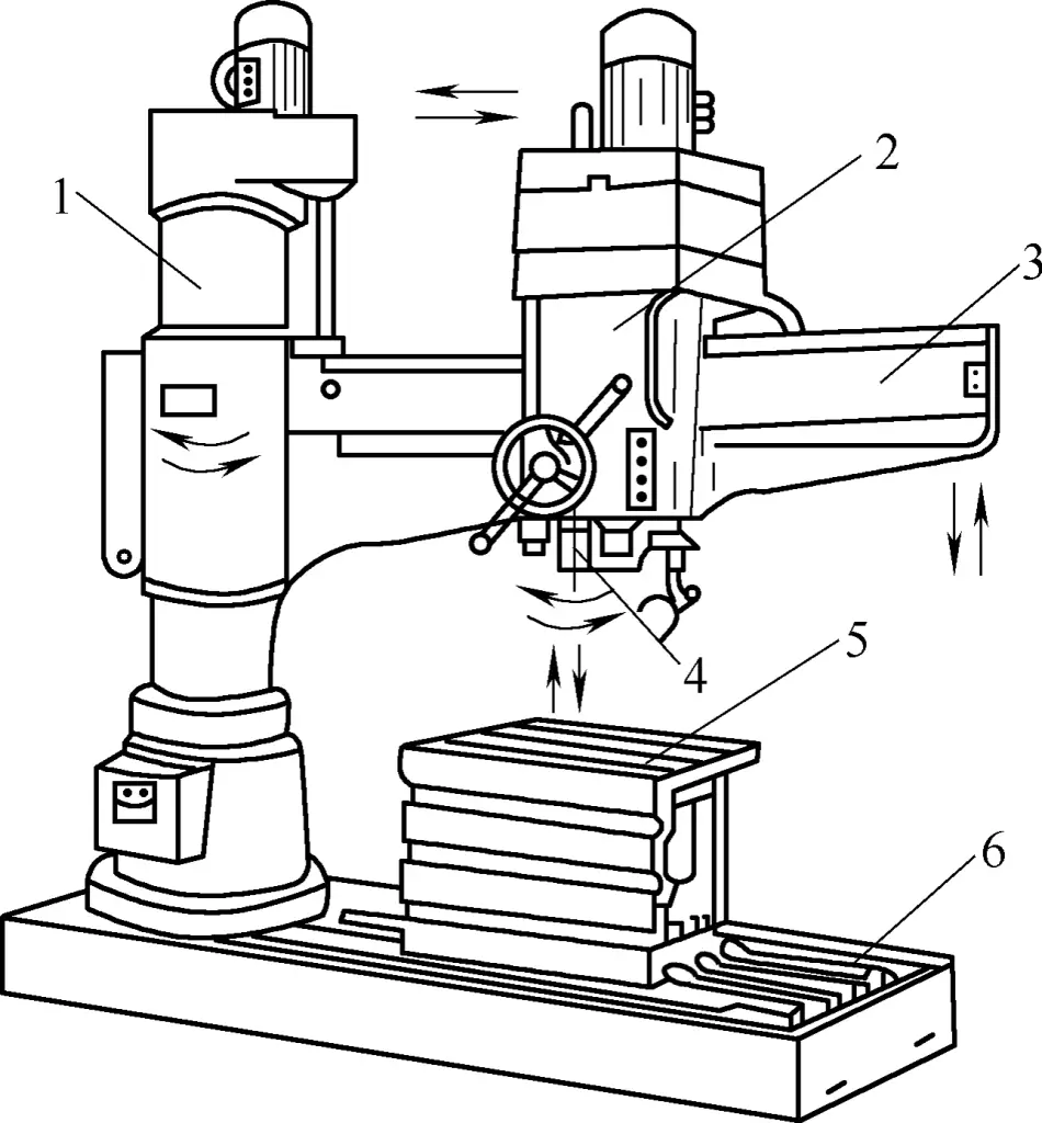
1—Column
2—Spindle box
3—Arm
4—Spindle
5—Worktable
6—Base
The spindle box 2 is mounted on the arm 3, which can rotate around the vertical column 1, and can move back and forth along the horizontal guide rail on the arm. Through these two movements, the spindle 4 can be adjusted to any position within the machine’s processing range. Therefore, radial drilling machines can perform hole processing over a very large range.
Radial drilling machines have a wide range of spindle speed and feed rate adjustments, allowing for high production efficiency and processing accuracy. When processing multi-hole workpieces on a radial drilling machine, the workpiece can remain stationary, and only the position of the arm and the spindle box on the arm need to be adjusted to conveniently align with the hole centers. In addition, the arm can also be raised and lowered along the column to adjust the height of the spindle box to suit the height of the workpiece processing area.
Currently, there are many specifications of radial drilling machines produced in China, among which the Z35 radial drilling machine is widely used in the assembly manufacturing industry, as shown in Figure 7.
The main performance and specifications of the Z35 radial drilling machine are as follows:
Maximum drilling diameter ϕ50mm
Spindle hole taper Morse No. 5
Maximum travel of spindle inside the headstock 350mm
Maximum travel of spindle along the arm guide rail 1050mm
Number of spindle speed levels 18
Spindle speed range 34~2000r/min
Number of feed rate levels 18
Feed rate range 0.3~1.2mm/r
Maximum travel of arm along the column 680mm
Main motor power 4~5kW
Press-fitting assembly is a common type of interference fit in assembly workshops. It is also a more economical and efficient assembly method compared to hot and cold fitting, and is an operational skill that assembly fitters should master. Most press-fitting assemblies are supplemented with key structures.
Press-fitting assembly often requires large pressing forces, so hydraulically controlled hydraulic press-fitting machines are generally used. This is because hydraulic systems are easy to adjust pressure, provide high force, allow for low fitting speeds, are easy to operate, safe to work with, and allow for monitoring of pressure magnitude and changes during the pressing process through system pressure gauges, achieving safe control of the press-fitting process.
Due to different usage scenarios, hydraulic press-fitting machines have their outstanding advantages for different workpieces and structures. Hydraulic press-fitting machines have small structural dimensions, are easy to operate and control, have a wide range of applications, and can be divided into vertical and horizontal types.
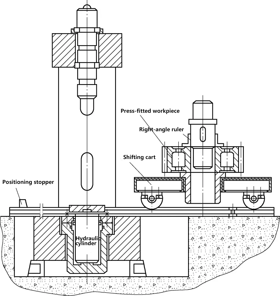
Figure 8 shows a frame-structured vertical hydraulic press-fitting machine, with its hydraulic system and control parts not shown. The hydraulic system of the press-fitting machine is very simple, with few system components due to its simple action. Since press-fitting machines generally require high working pressures (32MPa), variable displacement piston pumps are mostly used. Variable pumps can adjust output flow according to the press-fitting speed.
The system has a relief valve to protect the hydraulic pump and ensure system safety, filters to maintain system cleanliness, and other hydraulic components such as pressure gauges, check valves, oil pressure valves, stop valves, and control slide valves.
More fully-featured press-fitting machines are equipped with pressure curve recording and plotting devices during press-fitting. For example, horizontal train wheel axle press-fitting machines have strict requirements for pressure changes during the press-fitting process of train wheel axles. Therefore, the actual state of pressure changes needs to be reflected and recorded during the press-fitting process, with the pressure change process depicted in curve form as a basis for judging whether it meets the requirements, and then archived for storage.
Vertical and horizontal press-fitting machines differ in form, thus exhibiting their respective advantages and disadvantages in use.
There are two structural forms of vertical press-fitting machines. One is the top-mounted hydraulic cylinder, where the main hydraulic cylinder is set on the upper beam of the press-fitting machine, but the hydraulic cylinder must be a piston structure, otherwise it would rely on a piston-type secondary hydraulic cylinder to control the return of the hydraulic cylinder. The other is the bottom-mounted hydraulic cylinder, as shown in Figure 8, where the hydraulic cylinder is set inside the lower beam (machine base) of the press-fitting machine, and can use a plunger-type hydraulic cylinder, with the plunger returning by the self-weight of the plunger and connected components.
The frame also comes in frame and column types. Because the frame structure mostly uses welded connections, even if bolt pre-tightening structures are used, the contact surface between the side frame and the upper and lower beams is very large, so the frame itself has good rigidity and can adapt to large tonnage press-fitting. The column structure (often two-column) is simple and convenient for processing and scheduling, suitable for smaller tonnage press-fitting.
The biggest advantages of vertical press-fitting machines are: compact structure, small footprint, good workpiece centering during press-fitting, convenient vertical press-fitting operation, less likely to have skewing, jamming and other adverse phenomena, and the bottom-mounted plunger hydraulic cylinder is simpler in structure, lower in cost, smoother in return, and more reliable and reasonable in operation compared to the piston hydraulic cylinder.
Its disadvantages are: due to the upper beam, the hoisting operation of workpieces during the press-fitting process is inconvenient. However, if a moving cart is set up, loading and unloading of workpieces can be done outside the press-fitting machine, overcoming the structural disadvantage. The moving cart can be freely pushed on the guide rail, with positioning stops at the front end to ensure that the press-fitting workpiece is coaxial with the hydraulic cylinder press-fitting center, making operation very convenient.
Another issue is the bottom-mounted hydraulic cylinder structure. Although the press-fitting machine has a lower center of gravity and is more stable, during the press-fitting process, when the hydraulic cylinder plunger pushes upward, the workpiece being pressed also moves upward. Because the structure and dimensions of the press-fitted component are large and have significant self-weight, it appears unstable and less safe. Due to the wider frame, it takes up part of the press-fitting operation position, creating inconvenience and blind spots for press-fitting observation.
Horizontal press-fitting machines are the opposite of vertical ones. They require a larger installation area, with workpieces placed horizontally. Affected by self-weight, centering and adjustment are more difficult. Due to unstable centering and positioning, problems are more likely to occur during the press-fitting process and operation.
The plunger hydraulic cylinder stroke is not as large as that of vertical machines, and return is difficult. Horizontal press-fitting machines are mostly column structures, reducing horizontal dimensions, which is beneficial for operators to observe and approach the workpiece. Its outstanding advantage is the spacious environment, convenient for loading, unloading, and operation of workpieces, clear observation, stable workpiece placement, and no risk of falling.
The following points should be noted in the use and maintenance of press-fitting machines:
Cleaning during the machine assembly process is important for improving product assembly quality and extending product life. This is particularly important for bearings, precision components, seals, and parts with special cleaning requirements.
The cleaning process includes cleaning solutions, cleaning methods, and process parameters, which need to be determined based on factors such as workpiece cleaning requirements, production batch size, workpiece material, nature and adhesion status of surface grease, dirt, and mechanical impurities. At the same time, the selected cleaning solution should be compatible with the cleaning method. It should also be noted that the workpiece should have a certain intermediate rust prevention ability after cleaning.
The characteristics and applicable ranges of common cleaning methods are shown in Table 1.
Table 1 Characteristics and applicable ranges of common cleaning methods
| Cleaning method | Cleaning solution | Characteristics | Applicable range |
| Wiping | Gasoline, kerosene, light diesel oil, ethanol and chemical cleaning solutions | Simple operation, simple cleaning equipment, low productivity | Single-piece, small batch production of small and medium-sized workpieces and local cleaning of large pieces |
| Immersion cleaning | Suitable for various commonly used cleaning solutions | Simple operation; longer cleaning time, generally 2-20 minutes. Usually adopts multi-step cleaning | For larger batches of workpieces with more complex shapes. Cleaning of lightly adhered oil stains |
| Spray cleaning | Gasoline, kerosene, light diesel oil, chemical cleaning solutions, trichloroethylene and alkaline solution | Good cleaning effect, high productivity high, better working conditions, more complex equipment | For medium and large batch production workpieces, not suitable for complex shapes. Cleaning of severely adhered dirt and semi-solid oil stains |
| Vapor phase cleaning | Trichloroethylene vapor | Good cleaning effect, more complex equipment, high labor protection requirements | Small and medium-sized workpieces. Good for cleaning moderately adhered oil stains, effective in removing dirt |
| Ultrasonic cleaning | Gasoline, kerosene, light diesel oil, chemical cleaning solutions and trichloroethylene | Good cleaning effect, high productivity; more complex equipment maintenance and management | For small and medium-sized workpieces with high cleaning requirements, often used for final cleaning of workpieces |
| Combined immersion and spray cleaning | Gasoline, kerosene, light diesel oil, chemical cleaning solutions, trichloroethylene and alkaline solution | Good cleaning effect, high productivity; large floor space for cleaning equipment, more complex maintenance and management | For batch production, complex shapes, and workpieces with high cleaning requirements. Cleaning of oil stains and semi-solid oil stains |
| Combined vapor-immersion, vapor-spray, or vapor-immersion-spray cleaning | Trichloroethylene solution and trichloroethylene vapor | Same as above, but slightly lower productivity | Suitable for vapor phase cleaning, small-sized workpieces with high cleaning requirements. Can clean oil stains, especially the vapor-immersion combined spray type, which can clean severely adhered dirt, with good dirt removal effect |
1) Petroleum solvents
Petroleum solvents are easy to store and formulate rust preventives, and are a traditional cleaning solution. When using these cleaning solutions, fire prevention and ventilation safety measures must be considered.
Commonly used petroleum solvents mainly include gasoline, kerosene, and light diesel oil. For special requirements, similar organic solvents such as ethanol and acetone can be used.
Industrial gasoline and straight-run gasoline are mainly used for cleaning grease, dirt, and generally adhered mechanical impurities, suitable for steel and non-ferrous metal workpieces; aviation gasoline is used for cleaning high-quality workpieces.
The application of lamp kerosene and light diesel oil is similar to gasoline, but their cleaning ability is not as good as gasoline. They dry more slowly after cleaning but are safer than gasoline.
To prevent workpiece rusting, a small amount (such as 1% to 3% by mass) of displacement-type rust preventive oil or rust inhibitor additives can be added to petroleum solvents. Displacement-type rust preventive oils include 201, FY-3, 661, etc. Rust-preventive gasoline can also be self-formulated; the formula for rust-preventive gasoline is shown in Table 2.
This rust-preventive gasoline has strong cleaning ability, can clean hand sweat, inorganic salts, grease, etc., and provides intermediate rust protection for steel, copper alloys, and other workpieces. At the same time, operators should apply “liquid gloves” to their hands to prevent hand sweat from rusting workpieces and to avoid irritation of hands by gasoline, kerosene, diesel, etc.
Table 2 Rust-preventive gasoline formula
| Component | Mass fraction (%) |
| Petroleum sodium sulfate | 1 |
| Span-80 | 1 |
| Lauryl alcohol acylamide | 1 |
| 1% benzotriazole alcohol solution | 1 |
| Distilled water | 2 |
| No. 200 gasoline | 94 |
Petroleum solvents are generally used at room temperature. If heating is required, the oil temperature for lamp kerosene should not exceed 40°C, and for solvent kerosene should not exceed 65°C, and direct heating of the container with flames is not allowed. For mechanical oil, turbine oil, and transformer oil, the oil temperature should not exceed 120°C.
2) Alkaline solutions
When preparing alkaline solutions, a small amount of surfactant cleaning agent can be added to enhance cleaning ability. When cleaning with alkaline solutions, note: thick oil stains should be wiped off first; workpieces of different material properties should not be cleaned together; after cleaning, workpieces should be rinsed or washed clean with water and dried. Common alkaline solution formulas, process parameters, and applicability are shown in Table 3.
Table 3 Common alkaline solution formulas, process parameters, and applicability
| Composition/(g/L) | Main process parameters | Applicability |
| Sodium hydroxide 50-55 Sodium phosphate 25-30 Sodium carbonate 25-30 Sodium silicate 10-15 | Cleaning temperature 90-95°C Immersion or spray cleaning Cleaning time 10min | Steel workpieces, with severely adhered oil stains or small amounts of insoluble oil stains and impurities |
| Sodium hydroxide 70-100 Sodium carbonate 20-30 Sodium phosphate 20-30 | Cleaning temperature 90-95°C Immersion or spray cleaning Cleaning time 7-10min | Nickel-chromium alloy steel workpieces |
| Sodium hydroxide 5-10 Sodium phosphate 50-70 Sodium carbonate 20-30 | Cleaning temperature 80-90°C Immersion or spray cleaning Cleaning time 5-8min | Steel and copper alloy workpieces |
| Sodium hydroxide 5-10 Sodium phosphate ≈50 Sodium silicate ≈30 | Cleaning temperature 60-70°C Immersion or spray cleaning Cleaning time ≈5min | Aluminum and aluminum alloy workpieces |
3) Chemical cleaning solutions
Chemical cleaning solutions contain surfactants, also known as emulsifier cleaning solutions, which have good cleaning ability for grease and water-soluble dirt. These cleaning solutions are easy to prepare, stable and durable, non-toxic, non-flammable, safe to use, low-cost, and some chemical cleaning solutions also have certain intermediate rust prevention capabilities, making them very suitable for intermediate process cleaning during assembly. There are many formulas for chemical cleaning solutions; common chemical cleaning solution formulas, process parameters, and applicability are shown in Table 4.
Table 4 Common chemical cleaning solution formulas, process parameters, and applicability
| Composition and mass fraction (%) | Main process parameters | Applicability |
| 105 cleaning agent 0.5 6501 cleaning agent 0.5 Water remainder | Cleaning temperature 85°C Spray pressure 0.15MPa Cleaning time 1min | Steel workpieces. Mainly for cleaning oil stains and mechanical impurities primarily composed of machine oil |
| 664 cleaning agent 2-3 Water remainder | Cleaning temperature 75°C Immerse and wash, move up and down Washing time 3~4min | Steel workpieces. Not suitable for washing non-ferrous metal workpieces such as copper and zinc. Mainly for cleaning stearic acid, paraffin, vaseline, etc. |
| 6501 cleaning agent 0.2 6503 cleaning agent 0.2 Triethanolamine oleate 0.2 Water remainder | Cleaning temperature 35~45℃ Ultrasonic cleaning (working frequency 17~21kHz) Cleaning time 4~8min | Precision machined steel workpieces. Cleaning mineral oil and grinding paste residues containing chromium oxide, etc. |
| 6503 cleaning agent 0.5 TX-10 cleaning agent 0.3 Polyethylene glycol (relative molecular mass about 400) 0.2 Dibutyl phthalate 0.2 Trisodium phosphate 1.5~2.5 Water remainder | Cleaning temperature 35~45℃ Ultrasonic cleaning (working frequency 17~21kHz) Cleaning time 4min | Precision machined steel workpieces. Mainly for cleaning Grease |
| 664 cleaning agent 0.5 Pingping Jia cleaning agent 0.3 Triethanolamine 1.0 Oleic acid 0.5 Polyethylene glycol (relative molecular mass about 400) 0.2 Water remainder | Cleaning temperature 75~80℃ Immerse and wash, move up and down Cleaning time 1min | Precision machined steel workpieces. Very strong ability to clean grease |
4) Trichloroethylene
Trichloroethylene has advantages such as high degreasing efficiency, good cleaning effect, and non-flammability. With the addition of appropriate stabilizers, it can clean non-ferrous metal workpieces such as aluminum and magnesium alloys. However, its cleaning equipment is relatively complex, requiring a good ventilation system and cleaning liquid recovery system. Attention should also be paid to the corrosion prevention of workpieces and cleaning tanks.
Trichloroethylene is a strong solvent with a low boiling point, easy to vaporize and condense. It has a high vapor density and is not easily diffused, making it suitable for vapor cleaning. It can also be used for immersion cleaning, spray cleaning, or a combination of the three cleaning methods. When used for ultrasonic cleaning, it is particularly suitable for cleaning instrument parts, optical elements, and electronic components with high quality requirements.
In addition, there is ultrasonic cleaning. The mechanism of ultrasonic cleaning is to introduce ultrasonic vibrations into the cleaning liquid, causing a large number of cavitation bubbles to appear in the cleaning liquid, which gradually grow and then suddenly collapse.
When the bubbles collapse, they produce microwaves from the center outward, with pressures that can reach hundreds or even thousands of atmospheres, promoting the removal of oil stains adhered to the workpiece. At the same time, the strong oscillation of cavitation bubbles enhances and accelerates the emulsification and solubilization of the cleaning liquid on the oil stains, improving the cleaning ability.
The selection of cleaning methods and corresponding cleaning equipment and liquids should be based on specific conditions such as factory production scale, batch size, workpiece structure dimensions, shape characteristics, cleanliness requirements, material, and pre-cleaning conditions.
For large batch production with high production efficiency, cleaning equipment that matches it should be selected, with conveyor belt-style continuous operation, continuous input and output, and even the use of advanced automatic control technology, such as the cleaning machine shown in Figure 9.
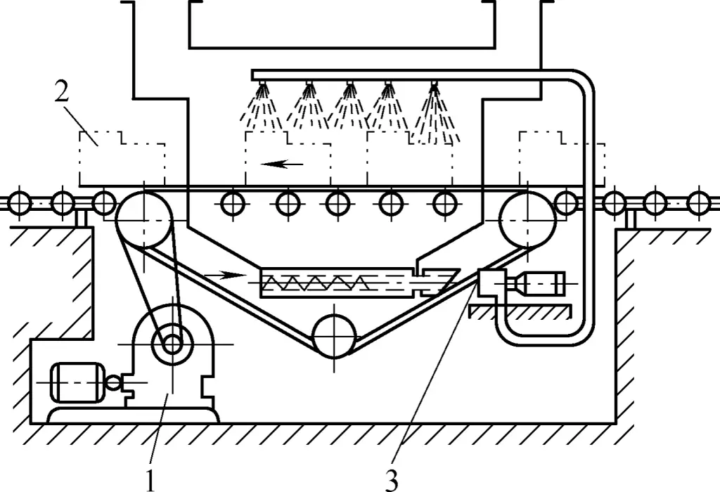
1—Electric motor
2—Workpiece
3—Circulation pump
It can also be equipped with some robotic arms and automatic adjustment and counting, cleaning liquid recovery and treatment, automatic inspection feedback, and other control systems. For larger workpieces and small batches, turntable or fixed cleaning chambers can be used, selecting different angles from different positions to spray cleaning liquid on the workpiece using cleaning nozzles.
During the cleaning process, the workpiece can be rotated as needed. After spray cleaning, stop spraying and use compressed air to blow clean and dry. The structure of the compressed air nozzle is shown in Figure 10; the cleaning nozzle is shown in Figure 11.
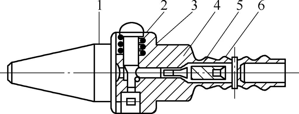
1—Nozzle
2—Switch
3—Spring
4—Push rod
5—Conical valve
6—Body
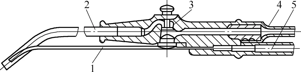
1—Detergent spray tube
2—Compressed air spray tube
3—Switch
4—Compressed air pipe
5—Detergent pipe
For small workpieces with severe oil stain adhesion, immersion or spray cleaning should be done first. To improve cleaning quality and shorten cleaning time, several different cleaning liquids are often used, with separate tanks for sequential cleaning, each tank focusing on different aspects of oil stain removal.
For workpieces with larger dimensions and mass, local cleaning is often used. The workpiece can be partially immersed in an ultrasonic cleaning tank for cleaning; special structural designs can also be made according to the shape of large workpieces or the requirements of local cleaning areas to achieve local cleaning.
For workpieces with very complex shapes or holes and grooves of varying sizes, ultrasonic cleaning with different vibration frequencies can be used. Cleaning operations should maintain a clean environment and strictly follow the process specifications, which is very important for achieving safe production.
1) Parts should be cleaned thoroughly before assembly. Before assembly, residual molding sand, chips, rust, etc. on the parts must be thoroughly removed. Places that easily retain debris such as holes and grooves should be cleaned particularly carefully, and burrs and sharp edges should be removed. Some parts, such as the interior of housings, need to be painted after cleaning.
If cleaning is not thorough, it will affect the assembly quality and service life of the machinery. For example, sliding guides may accelerate wear due to residual sand particles and chips between mating surfaces, and even serious accidents such as guide “seizure” may occur.
2) Pay attention to cleaning chips generated during the assembly process. During assembly, some parts require supplementary processing, such as drilling, reaming of locating pin holes, and tapping threads. The chips produced must be removed. When necessary, supplementary processing should be done away from the assembly site to prevent chips from falling onto mating surfaces.
3) Do not damage the original precision when cleaning important mating surfaces. Rust and dried paint on machined surfaces can be removed with files, scrapers, and sandpaper. For important mating surfaces, extra care must be taken during cleaning to avoid damaging their original precision.
4) Do not damage parts during the cleaning process. Care should be taken not to damage parts during cleaning. If there are slight dents or burrs, they can be repaired with a grinding stone or scraper and then cleaned again.
5) Do not use gasoline to clean rubber parts. For rubber parts such as sealing rings, it is strictly forbidden to clean them with gasoline to prevent deformation. Cleaning liquid or alcohol should be used for cleaning.
6) Do not use cotton yarn to clean rolling bearings. When cleaning rolling bearings, tools such as brushes should be used, not cotton yarn, to prevent cotton fibers from entering the bearing and affecting the assembly quality.
7) Prevent secondary contamination of cleaned parts. For parts that have already been cleaned, do not wipe them casually during assembly, as this can easily dirty the parts and cause secondary contamination.
After cleaning, the parts should be allowed to dry of oil drops before assembly to prevent oil contamination from affecting the cleanliness quality of the assembly. If cleaned parts are not immediately assembled, measures should be taken to prevent extended exposure, which could lead to dust contaminating the parts.
8) Do not neglect to add lubricating oil and make necessary adjustments before assembly. Mating surfaces generally need to be lubricated with oil before assembly, otherwise phenomena such as scratching of mating surfaces may occur during assembly. For moving connection mating surfaces, failure to lubricate can easily cause resistance in movement, accelerated wear, or even surface fuzzing due to lack of lubrication.
Burrs resulting from machining on parts and dents caused by collisions during process transfer are often easily overlooked, thereby affecting assembly precision. Therefore, attention should be paid to rectifying these defects on parts during assembly.