I. Basic Process Knowledge
1. Principle of Grinding and Forms of Cutting
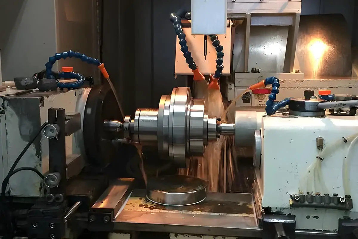
Grinding is an operation where abrasive powder or abrasive is embedded or coated on the surface of a grinding tool or workpiece for micro-cutting processing, as shown in Figure 1.
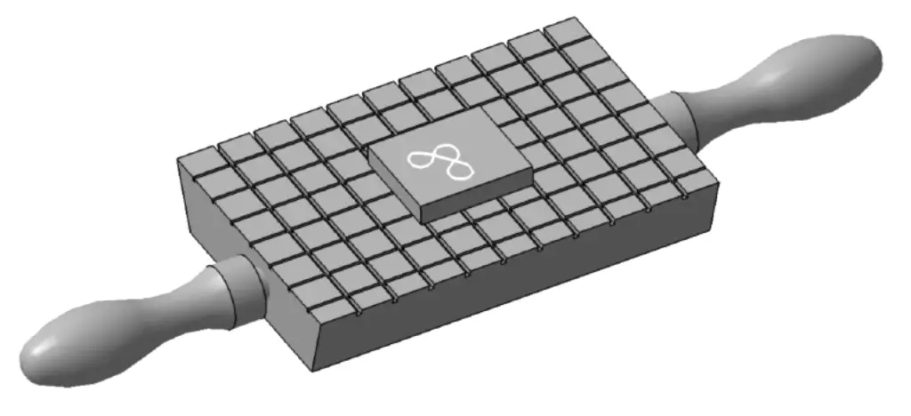
As a special form of processing, abrasive particles act as numerous tiny cutting tools for physical cutting of the workpiece. When using chemical abrasives (such as abrasives formulated from chromium oxide and stearic acid), it can also polish the processed materials.
The principle of polishing during the grinding process involves an increase in the temperature of the material being ground due to friction and cutting. The cutting heat is not easily dissipated, resulting in a thin oxide film forming quickly on the processed metal workpiece surface upon contact with air (the oxide film forms on steel in 0.05s and lead in 0.04s). Using chemical abrasives can remove this oxide film during grinding, allowing the continuous formation and removal of the oxide film, thereby continually reducing the surface roughness value and polishing the workpiece.
After grinding, the dimensional accuracy of parts can reach 0.001 to 0.005 mm, and the surface roughness value can reach Ra0.2 to 0.05 μm. Meanwhile, the wear resistance and corrosion resistance of the parts are also improved.
From the above, the forms of grinding cutting can be classified into three types:
(1) Embedded Grinding Method
Abrasive particles are evenly spread on the working surfaces of two grinding tools, which are then ground against each other so that the abrasive particles are directly embedded into the working surface of the grinding tool. This grinding tool can then be used to grind the workpiece (some oil can be added to the grinding surface during grinding).
The biggest advantage of this grinding tool is that the particles are firmly embedded like many small blades scraping the surface of the workpiece simultaneously. In grinding operations, the cutting amount is relatively large, usually reaching several micrometers, with high cutting dimensional accuracy. The disadvantage is low cutting efficiency and it is typically suitable for grinding parts with general precision requirements.
(2) Coating Grinding Method
Coating grinding involves applying abrasive to the surface of the workpiece or grinding tool. Due to the presence of grinding fluid, the abrasive particles possess a certain degree of fluidity. Compared to the purely multi-edge cutting action of embedded grinding, the abrasive also has rolling and friction effects on the workpiece surface. Therefore, under the premise of sufficient grinding fluid, the cutting efficiency is higher and it is easy to achieve a lower surface roughness value. It is generally suitable for grinding parts with medium precision requirements.
(3) Polishing
Grinding with chemical abrasives, focusing on cutting while primarily utilizing their chemical grinding performance, mainly for polishing.
2. Grinding Tools
(1) Abrasives
1) Common Types of Abrasives and Their Applications
Table 1 Common Types of Abrasives and Their Applications
| Types of Abrasives | Name of Abrasive | Application Range |
| Aluminum Oxide Series | Brown Fused Alumina | Mainly used for rough and precision grinding of cast iron, steel, and brass |
| White Fused Alumina | Mainly used for precision grinding of quenched steel, high-speed steel, high-carbon steel, and thin-walled parts | |
| Chromium Oxide | Mainly used for grinding measuring tools, instrument parts, and surfaces requiring low surface roughness value | |
| Monocrystalline Alumina | Mainly used for grinding high-strength and high-toughness materials | |
| Carbide Series | Black Carbide | Mainly used for grinding black copper castings, bronze castings, aluminum castings, castings, marble, granite, ceramics, and glass |
| Aluminum Carbide | Mainly used for grinding cemented carbide, hardened steel, etc. | |
| Boron Carbide | Mainly used for grinding workpieces made of cemented carbide, hardened steel, optical glass, and gemstone materials, especially suited for coarse grinding workpieces with larger allowance | |
| Diamond | Synthetic Diamond | Mainly used for rough and precision grinding of cemented carbide, synthetic gems, semiconductors, and other high-hardness brittle materials |
| Other Oxides Series | Iron Oxide | Precision grinding and polishing of steel, iron, glass, and other materials |
| Chromium Oxide |
2) Common Abrasive Models and Applications
Abrasive powders are generally used for coarse grinding; the larger the grain number, the finer the abrasive. Micro-powders are generally used for semi-precision grinding and precision grinding; the smaller the number, the finer the grain, as shown in Table 2.
Table 2 Common Abrasive Models
| Grinding particle size | Use | Achievable surface roughness Ra/μm |
| F100~F220(Powder) | Rough grinding of general parts | 3.2~0.04 |
| F280 or F320~F400(Micro Powder) | Rough grinding process of general parts | 0.2~0.1 |
| F500~F800(Micro Powder) | Fine grinding of general parts, semi-fine grinding of precision parts | 0.1~0.05 |
| F1000 or F1200 below (micro powder) | Fine grinding of precision parts | 0.05 or finer |
(2) Grinding agent
When manually preparing grinding agents, reasonable selection of abrasive particle size should be made (see Table 1), and then mixed with a certain proportion of stearic acid, dilution oil (kerosene, gasoline, engine oil), etc.
For preparing a coarse grinding agent, 8% (by mass fraction, the same below) of abrasive (grinding powder or micro powder), 4% of stearic acid, 8% of oleic acid, 40% of transformer oil and kerosene each, plus a small amount of beeswax, etc., can be used. For fine grinding, oleic acid is not added, more kerosene is used.
With the continuous promotion and application of grinding technology, grinding paste made of abrasive, lubricating liquid, and stearic acid is now widely used. When in use, the grinding paste is diluted with engine oil and then used. Common grinding paste components include 40% diamond abrasive, 20% chromium oxide, 25% stearic acid, 10% capacitor oil, and kerosene. Refer to the relevant product information when using.
(3) Lapping tools
1) Lapping tool material
The principle for selecting lapping tools is that the hardness of the tool material should be lower than that of the abrasive, and generally, soft and wear-resistant materials perform better. Among them, ductile cast iron, low-carbon steel, copper, and aluminum are mostly suitable for embedded lapping tools, Babbitt alloy is suitable for precision bearing grinding, glass and polyester fabrics are mainly used for polishing, while hardwood materials and leather lapping tools are mainly suitable for polishing non-ferrous metals.
2) Common lapping tool structures and forms
The structure of the lapping tool usually needs to match the shape of the surface of the workpiece being lapped. As shown in Figure 2a, lapping plates are mainly suitable for lapping large flat surfaces. Lapping plates with grooves are generally used for rough surface lapping, while smooth plates are generally used for fine surface lapping.
The bar-shaped lapping plates shown in Figure 2b are mainly suitable for the lapping of narrow and long bar-shaped workpieces and internal grooves; Figure 2c shows a commonly used lapping sleeve, suitable for lapping external cylindrical surfaces; Figure 2d shows a lapping tool mainly used for lapping internal cylindrical surfaces. Similar to the lapping plates, lapping rods with curved grooves are generally used for rough lapping of internal bores, while smooth external cylindrical surfaces are generally used for fine lapping of internal bores.
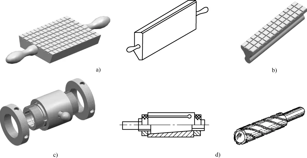
a) Large lapping plate
b) Lapping plate for narrow flat surfaces
c) Lapping sleeve for external cylindrical surfaces
d) Lapping rod for internal cylindrical surfaces
3. Grinding Allowance and Grinding Dosage
(1) Grinding Allowance
It is generally appropriate to have a grinding allowance of 0.005~0.03mm. The specific selection principle can be referred to as follows:
1) Depending on the geometry and accuracy requirements of the workpiece, larger areas or more complex shapes requiring high accuracy should take a larger grinding allowance, about 0.03mm worth of grinding over 100mm length.
2) If the quality of pre-processing (the previous step, such as fine grinding, scraping, etc.) is high, the grinding allowance can be smaller, about 0.015mm or less over 100mm length; otherwise, a larger grinding allowance should be taken.
3) From a practical standpoint, for workpieces with high requirements for double-sided, multi-sided, and positional accuracy, and where there is no equipment to ensure quality during pre-processing, the grinding allowance should be considered practically.
(2) Grinding Dosage
Based on experience, grinding pressure can be selected from Table 3.
Table 3 Grinding Pressure Selection Table
| Grinding Type | Grinding Pressure / MPa | |||
| Flat | External Circle | Internal Hole | Others | |
| Press-fitting Grinding | 0.01-0.1 | 0.05-0.15 | 0.04-0.16 | 0.03-0.1 |
| Coating Grinding | 0.1-0.25 | 0.15~0.25 | 0.12~0.28 | 0.08~0.12 |
Note: The inner hole diameter range is ϕ5~ϕ20mm.
Based on experience, grinding speed can be selected from Table 4.
Table 4 Grinding Speed Selection Table
| Grinding Type | Grinding Speed /(m/min) | ||||
| Single Side | Double Side | External Circle | Internal Hole | Others | |
| Press-fitting Grinding | 10~30 | 10~15 | 10~25 | 10~20 | 2~8 |
| Coating Grinding | 20~120 | 20~60 | 50~75 | 50~100 | 10~70 |
Note: 1. For softer materials or high precision requirements, the speed can be set to a lower value.
2. The inner hole diameter range is ϕ6~ϕ10mm.
II. Basic Operational Skills
1. Grinding Plane Process
1) Clean the working surfaces of the grinding tool and the workpiece to be ground.
2) Apply the grinding agent evenly on the grinding plate.
3) Attach the surface of the workpiece that needs to be ground to the grinding plate.
4) Grinding trajectory. Linear grinding motion can achieve higher geometric accuracy and is suitable for narrow and long planes with steps, but it is difficult to achieve low surface roughness values.
Figure-8 or figure-8 shaped grinding motion is used for grinding small flat workpieces, allowing the two surfaces being ground to maintain uniform contact, which helps improve grinding quality.
5) Control the grinding speed and grinding pressure during the grinding process (as mentioned earlier). To achieve better grinding results, the applied pressure and speed can be flexibly adjusted within a certain range.
During coarse grinding or grinding smaller hard workpieces, higher pressure and slower speed can be used. For fine grinding or grinding larger workpieces, smaller pressure and faster speed should be applied.
6) After grinding for a period of time, the workpiece should be reversed or the angle of grinding should be adjusted to prevent uneven grinding.
7) As shown in Figure 3, check the flatness error of the ground surface with a dial indicator. If there is uneven grinding thickness, apply greater pressure to the thicker areas and grind again to correct it.
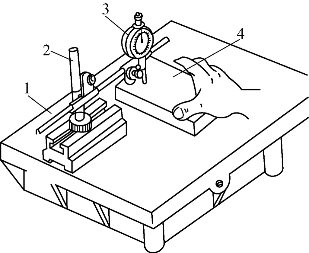
1—Inspection Plate
2—Indicator Stand
3—Dial Gauge
4—Workpiece
8) When grinding narrow planes, the backing iron can be used to move the workpiece being ground together to eliminate the bouncing phenomenon during grinding, enabling smooth movement of the workpiece. As shown in Figure 4, it demonstrates the grinding method for the inner narrow surface of a right-angle ruler.
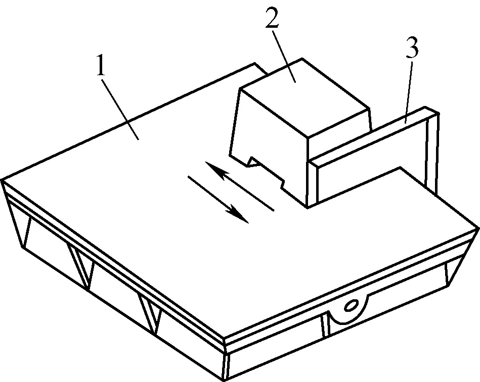
1—Plate
2—Back Iron
3—Right-Angle Ruler
2. Cylindrical Surface Grinding Process
Grinding inner and outer cylindrical surfaces can be done purely by hand or with a machine tool in conjunction with manual operation. However, the quality and efficiency of manual grinding are not high, so the latter method is generally employed.
(1) Inner Cylindrical Surface Grinding Process
The grinding process will be illustrated with an example of grinding a sleeve.
1) Grinding Allowance
The grinding allowance should be determined based on the size and accuracy of the part, generally within the part tolerance range. The principle is that the grinding allowance should not exceed 0.005mm, and the thickness of the metal layer removed in each grinding should not exceed 0.002mm.
2) Grinding Method for Sleeve-Type Parts
When replacing a sleeve with a smaller diameter, a combination of manual and machine grinding can be used. For larger inner diameters, manual grinding can be used. As shown in Figure 5, the specific grinding operation method is as follows:
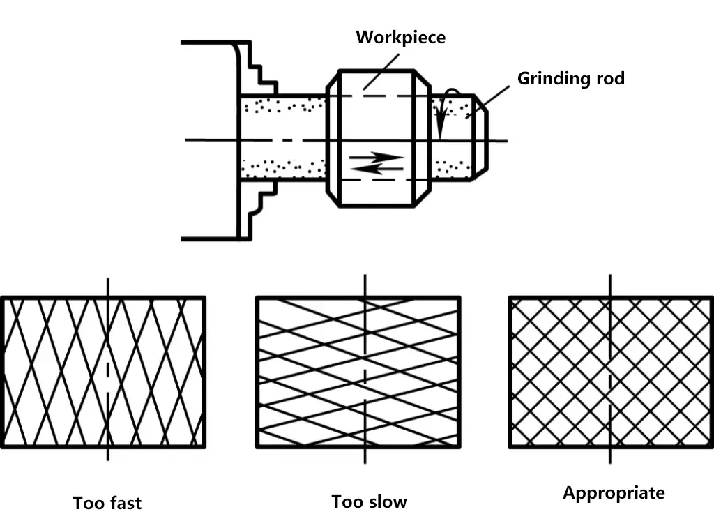
1) Clamp the grinding rod tightly in the lathe chuck and rotate it, then place the sleeve on the grinding rod for grinding. Generally, the length of the working part of the grinding rod is 1.5 to 2 times the length of the workpiece.
2) Apply the grinding agent evenly on the inner surface of the sleeve. Push the sleeve manually, performing grinding through the rotation of the grinding rod and the reciprocating motion of the sleeve along the axial direction on the grinding rod.
3) The general speed of the grinding rod is 100 r/min for diameters less than ϕ100 mm, and 50 r/min for diameters greater than ϕ100 mm. The reciprocating speed of the workpiece can be controlled based on the network pattern that appears during grinding. When a 45° pattern appears, it indicates that the sleeve’s movement speed is appropriate.
4) Operational Precautions for Sleeve Grinding
- During coarse grinding or grinding sleeves with smaller inner diameters, apply higher pressure and a slower speed. For fine grinding or larger sleeves, use lower pressure and a faster speed.
- When pure manual grinding is used, make sure to keep the sleeve center as vertical to the ground as possible to prevent eccentric grinding.
- Ensure that no impurities are mixed into the grinding agent to avoid scratching the inner surface of the sleeve.
- The grinding agent should be thinly and evenly applied on the inner surface of the sleeve, avoiding uneven application.
- Wipe off any grinding agent extruded from the hole promptly to prevent expanding the hole’s edge.
- After grinding for a period of time, attention should be paid to reversing and changing the grinding direction to prevent ovality and tapering in the sleeve hole.
- The sleeve should not be clamped too tightly to prevent bowing and deformation.
- During grinding, if the temperature exceeds 50℃, stop grinding.
(2) Outer Cylindrical Surface Grinding Process
The operation method and precautions are similar to those of inner cylindrical surface grinding. During grinding, first clamp the workpiece on the machine, as shown in Figure 6. Apply a thin and even layer of grinding agent on the outer cylindrical surface of the workpiece, put on the grinding tool, adjust the grinding clearance (which can be adjusted based on coarse and fine grinding allowances), then start the machine, and manually hold the grinding sleeve to move back and forth at a uniform speed along the entire axial length of the workpiece without pausing at any segment.
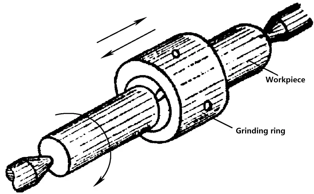
Simultaneously, the grinding sleeve should also be intermittently rotated to eliminate roundness error caused by the weight of the workpiece or grinding tool. After grinding for a certain period, the grinding quality should be checked. If out-of-tolerance roundness is detected, mark it appropriately, adjust the clearance, and focus on grinding the marked areas. If taper errors are found on the workpiece, reverse the grinding tool or workpiece, re-adjust the grinding clearance, and perform corrective grinding.

