Metal Machinability: Properties & Processes
Have you ever wondered how the material of a metal part affects its manufacturability? This article explores the intricate relationship…
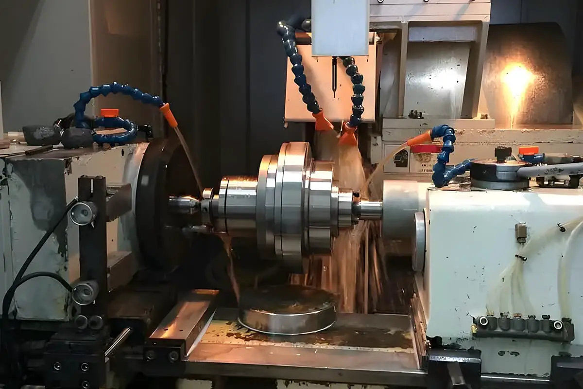
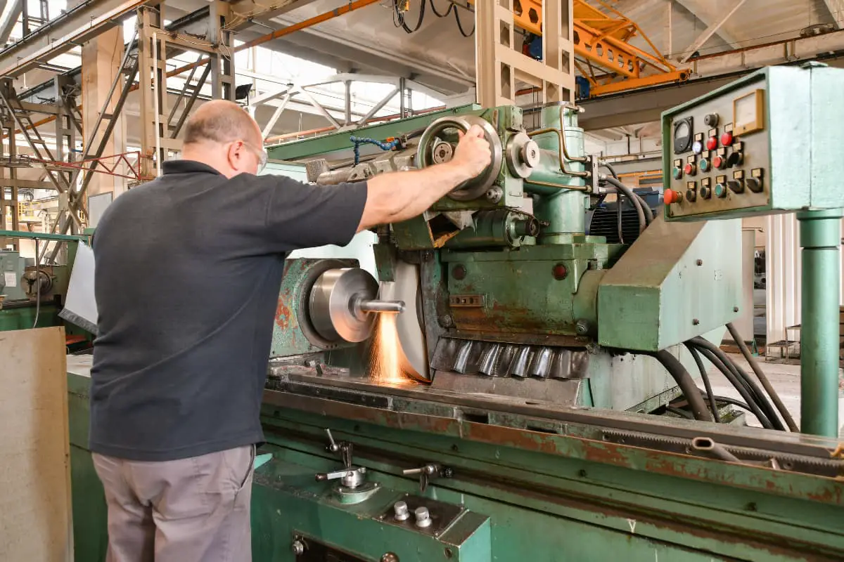
Imagine transforming rough, raw metal into precise, polished parts with near-microscopic accuracy. The grinding process in mechanical engineering does exactly that, using abrasive tools to achieve exceptional surface finishes and tight tolerances. This article delves into various grinding methods, types of grinding machines, and the science behind grinding wheels, explaining their crucial role in modern manufacturing. Dive in to discover how mastering these techniques can enhance your projects, ensuring superior quality and efficiency in your work.
All machine tools that use abrasives and grinding tools (such as grinding wheels, abrasive belts, grindstones, and abrasives) as tools for cutting workpieces belong to the category of grinding machines. Any processing method that uses grinding wheels and other abrasives or grinding tools on grinding machines to cut workpieces, making them meet predetermined requirements in terms of shape, precision, and surface quality, is referred to as grinding.
Each abrasive grain on the surface of the grinding wheel acts as a cutting tool, with the shape, size, and distribution of its cutting edges being irregular and random. Typically, cutting involves a large negative rake angle and a small clearance angle.
Generally, the back engagement during grinding is small, and the metal layer removed in a single stroke is thin. The dimensional tolerance level of grinding processing is IT7~IT5, and the surface roughness value is Ra0.8~0.2μm. Using high-precision grinding methods, the surface roughness value can reach Ra0.1~0.006μm.
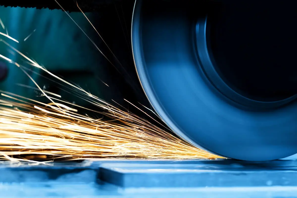
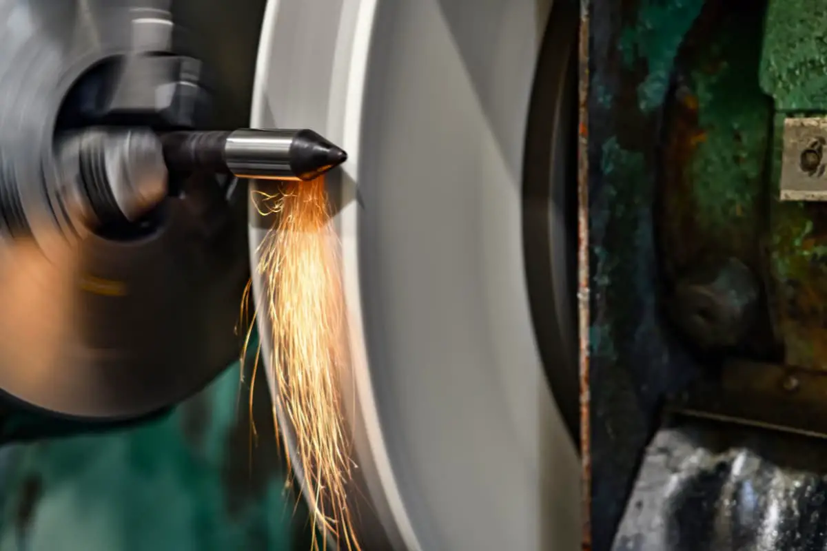
The general grinding speed is around 35m/s, and it can reach 60m/s during high-speed grinding. Currently, grinding speeds have developed to 120m/s. However, during the grinding process, the grinding wheel exerts strong pressure and friction on the workpiece, generating a large amount of cutting heat, with the instantaneous temperature in the grinding area reaching around 1000℃.
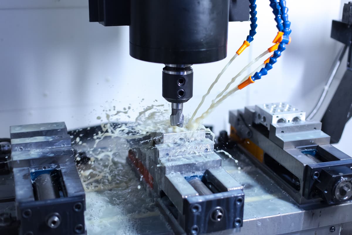
In production practice, measures to reduce the cutting temperature during grinding include adding a large amount of cutting fluid, reducing the back engagement, appropriately reducing the grinding wheel speed, and increasing the workpiece speed.
In terms of workpiece materials, grinding can process both soft and hard materials; in terms of workpiece surfaces, many surfaces can be ground.
During the grinding process, the abrasive grains on the surface of the grinding wheel gradually become blunt. The cutting resistance acting on the abrasive grains increases, causing the blunt grains to break and fall off, exposing sharp cutting edges to continue cutting. This is the self-sharpening of the grinding wheel, which maintains good cutting performance.
During grinding, because many abrasive grains participate in grinding at the same time and cut with a negative rake angle, the radial grinding force is very large, generally 1.5~3 times the tangential force. Therefore, when grinding shaft parts, center supports are usually used to improve the rigidity of the workpiece and reduce processing errors caused by deformation. In the final stage of grinding processing, light grinding without radial feed is usually performed a certain number of times.
The application scope of grinding is very wide, capable of processing internal and external cylindrical surfaces, internal and external conical surfaces, flat surfaces, shaped surfaces, and combined surfaces, etc., as shown in Figure 1.
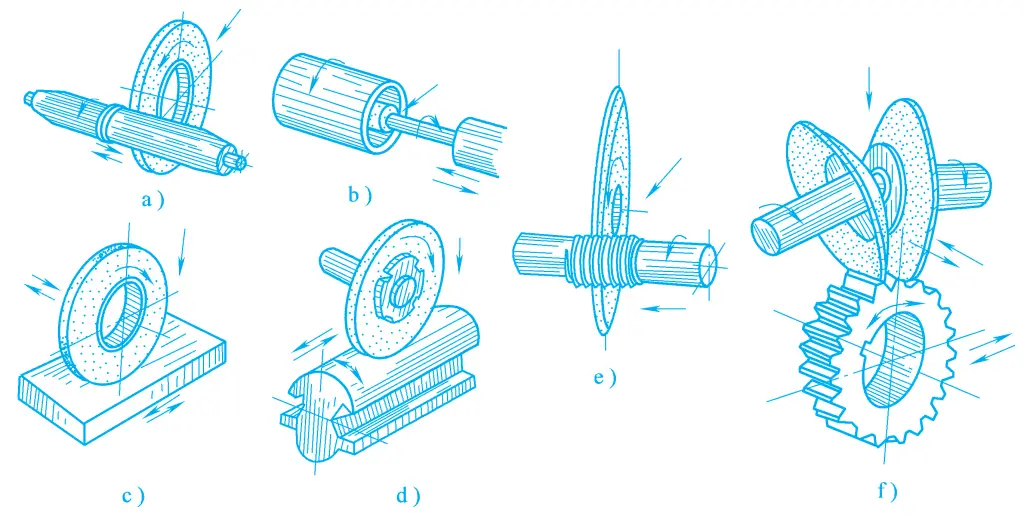
a) External cylindrical grinding
b) Internal grinding
c) Surface grinding
d) Form grinding
e) Thread grinding
f) Gear grinding
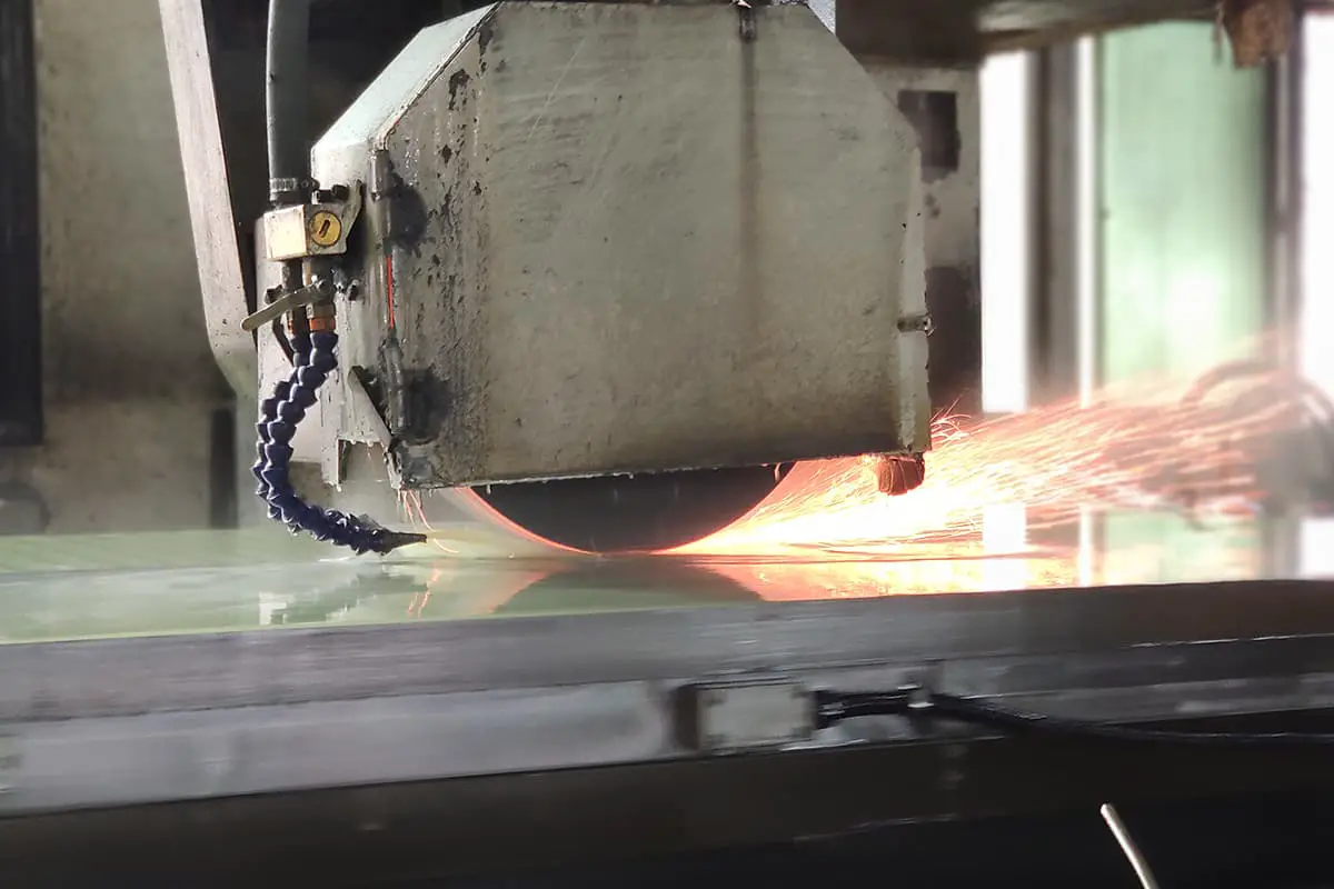
Currently, grinding is mainly used for finishing, workpieces that have been quenched and other special materials with high hardness, which can almost only be processed by grinding. Additionally, grinding can also be used for rough machining, such as rough grinding of workpiece surfaces, removing the hard skin on steel ingots and castings, cleaning the burrs on forgings, polishing the gates and risers on castings, and can also use thin grinding wheels to cut profiles of various hardnesses.
Due to the increasing number of high-precision, hardened parts on modern machines, the proportion of grinding in modern machine manufacturing is increasing. Moreover, with the development of precision blank manufacturing technology and the application of high productivity grinding methods, it has become possible for some parts to be completed directly by grinding, which will make the application of grinding more widespread.
Grinding machines are the most diverse type of machine tools, occupying a very important position in the machinery manufacturing industry. In addition to processing quenched and other high-hardness materials, when machining parts with a tolerance grade greater than IT7 on a grinding machine, it is much easier than on other machine tools, and also very economical. The ability to easily obtain high precision in grinding is due to the fact that the grinding tool can cut off very thin cutting allowances during finishing.
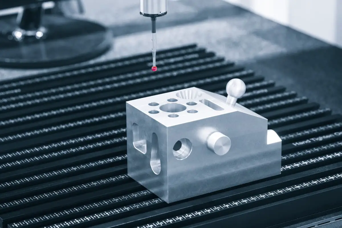
Additionally, the spindle of the grinding machine adopts dynamic pressure or hydrostatic bearings, which have high rotational accuracy and vibration resistance. The feed motion of the grinding machine often uses smooth hydraulic transmission, combined with electrical control to achieve semi-automatic and automatic operation. With the application of automatic measuring devices on grinding machines, the reliability of grinding processing quality has greatly increased.
There are many types of grinding machines, among which the main types include the following:
External cylindrical grinding machines include universal external cylindrical grinding machines, ordinary external cylindrical grinding machines, centerless external cylindrical grinding machines, etc.
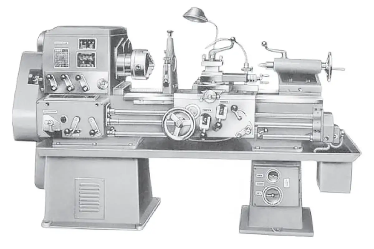
The M1432A type universal external cylindrical grinding machine is a universal external cylindrical grinding machine of ordinary precision level that has undergone a major improvement. It is mainly used for grinding the external cylindrical and internal holes of cylindrical or conical parts with tolerance grades of IT6 to IT7, with a maximum grinding external diameter of 320mm and a maximum grinding internal hole diameter of 100 mm, and can also grind the shoulders, end faces, and rounded corners of stepped shafts.
The surface roughness values are between Ra1.25 and 0.08μm. This machine has a wide range of processes, but low productivity, suitable for single-piece, small batch production or use in tool workshops and machine repair workshops. Figure 2 shows the M1432A type universal external cylindrical grinding machine, which is composed of the following main parts.
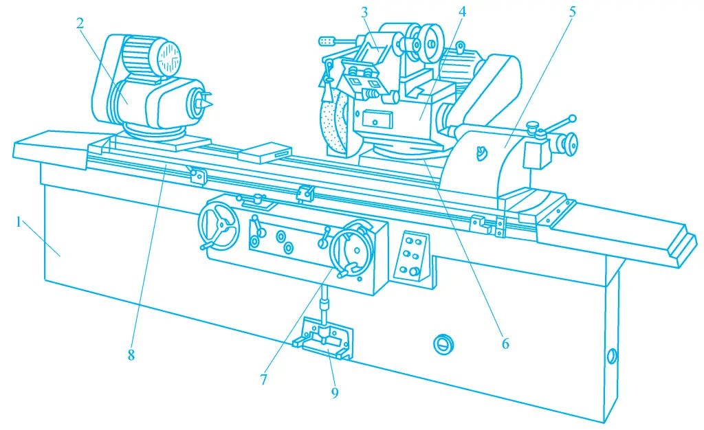
1—Bed
2—Headstock
3—Internal grinding device
4—Wheel head
5—Tailstock
6—Slide saddle
7—Handwheel
8—Worktable
9—Foot pedal control board
1) Bed
The bed is the basic supporting component of the grinding machine, equipped with components such as the headstock, grinding wheel frame, tailstock, and worktable. Inside the bed, there are hydraulic cylinders and other hydraulic components to drive the movement of the worktable and the cross saddle.
2) Headstock
The headstock is used to clamp the workpiece and drive its rotation. When the headstock body rotates at an angle, a short conical surface can be ground; when the headstock rotates 90° counterclockwise in the horizontal plane, a small flat surface can be ground.
3) Internal Grinding Attachment
The internal grinding attachment is used to support the grinding wheel spindle component for grinding internal holes, driven by a separate internal grinding wheel motor.
4) Grinding Wheel Frame
The grinding wheel frame is used to support and transmit the high-speed rotation of the grinding wheel spindle. The grinding wheel frame is mounted on the saddle, and when grinding a short cone, the position of the grinding wheel frame can be adjusted within ±30° at a certain angle.
5) Tailstock
The function of the tailstock is to support the workpiece together with the tip (rear tip) mounted on the tailstock sleeve and the front tip on the headstock spindle, to achieve precise positioning of the workpiece.
The tailstock uses spring force to press tightly against the workpiece, to automatically compensate for the elongation of the workpiece due to thermal expansion during the grinding process, avoiding bending deformation of the workpiece and excessive wear of the tip hole. The retraction of the tailstock sleeve can be manual or hydraulically driven.
6) Saddle and Cross Feed Mechanism
By rotating the cross feed handwheel, the cross feed mechanism drives the saddle and the grinding wheel frame to move laterally. The hydraulic device can also be used to make the grinding wheel frame perform rapid advance and retreat or periodic automatic cutting feed.
7) Worktable
The worktable consists of two layers, the upper worktable can rotate a very small angle relative to the lower worktable in the horizontal plane, for grinding long conical surfaces with a small taper. The headstock and tailstock are mounted on the surface of the upper worktable, and they move longitudinally back and forth along the bed guideways together with the worktable.
According to different grinding methods, internal grinding machines can be divided into ordinary internal grinding machines, planetary internal grinding machines, centerless internal grinding machines, etc.
According to the different shapes of the grinding wheel working surface and the worktable, ordinary surface grinding machines can be divided into horizontal spindle rectangular table surface grinding machines, vertical spindle rectangular table surface grinding machines, horizontal spindle rotary table surface grinding machines, vertical spindle rotary table surface grinding machines, etc.
It includes tool curve grinders, drill bit groove grinders, etc.
It includes universal tool grinders, broach blade grinders, hob blade grinders, etc.
It includes spline shaft grinders, crankshaft grinders, gear grinders, thread grinders, etc.
It includes honing machines, lapping machines, belt grinders, ultra-precision machine tools, wheel machines, etc.
Generally, grinding processing uses the high-speed rotation of the grinding wheel as the main motion, while the feed motion depends on the surface shape of the workpiece being processed and the grinding method used. It can be completed by the workpiece or the grinding wheel, or by both.
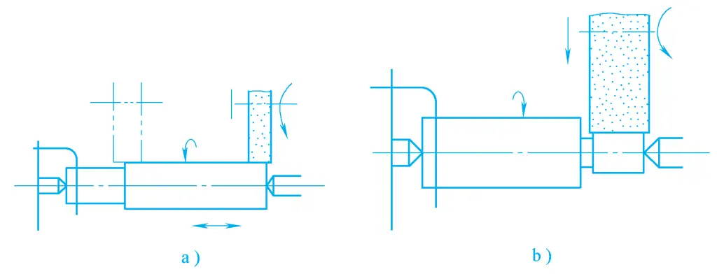
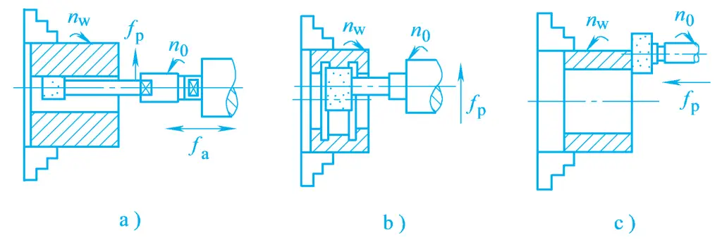
Figure 3 shows several typical grinding processing methods used on universal cylindrical grinders, where Figure 3a, 3b, 3d are using the longitudinal grinding method to grind external cylindrical surfaces and internal/external conical surfaces. At this time, the machine needs three surface forming motions: the rotation motion of the grinding wheel n o , the longitudinal feed motion of the workpiece f a , and the circumferential feed motion of the workpiece n w .
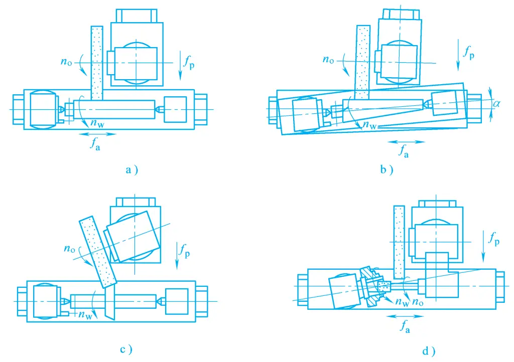
a) Longitudinal grinding of external cylindrical surfaces
b) Using longitudinal grinding to grind long conical surfaces by turning the worktable
c) Grinding short conical surfaces with the infeed method by turning the grinding wheel frame
d) Using longitudinal grinding to grind internal conical surfaces by turning the headstock
Figure 3c shows the grinding of short conical surfaces with the infeed method, where only the rotation of the grinding wheel and the circumferential feed movement of the workpiece are present. For processing to meet certain size requirements, there is also a need for lateral feed movement of the grinding wheel f p (for reciprocating longitudinal grinding, it is a periodic intermittent feed; for infeed grinding, it is a continuous feed). In addition, the machine tool has two auxiliary movements, rapid lateral advance and retreat of the grinding wheel and retraction of the tailstock sleeve, to facilitate loading and unloading of the workpiece.
The most commonly used tool in grinding processing is the grinding wheel, which is a special tool. Each abrasive grain on it is equivalent to a cutting tool, and the distribution of abrasive grains on the grinding wheel is shown in Figure 4.
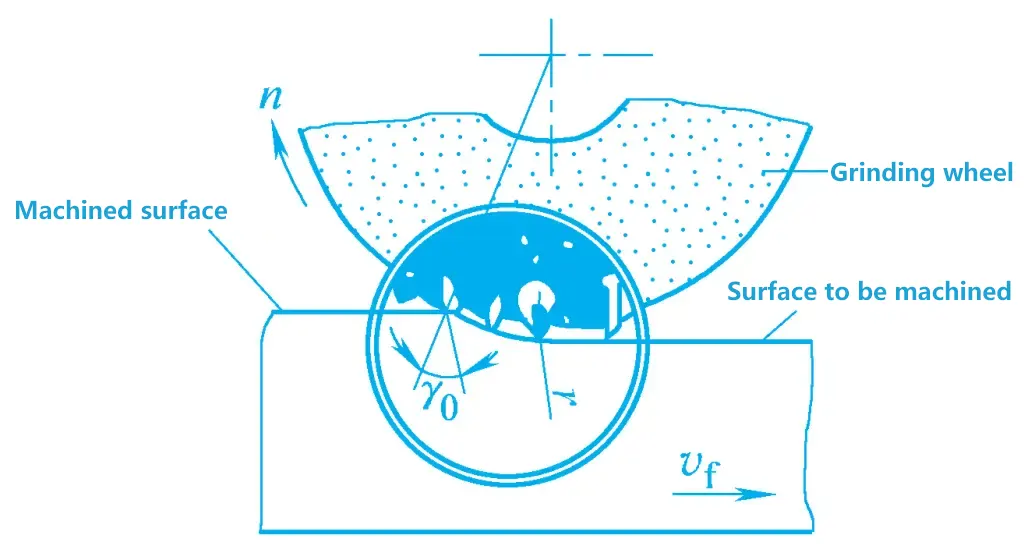
During grinding, the protruding abrasive grains with sharp edges cut off fine chips from the surface of the workpiece; the blunt or less protruding abrasive grains can only scratch fine grooves on the surface of the workpiece; the more recessed abrasive grains produce sliding friction with the surface of the workpiece, the latter two types of abrasive grains produce dust during grinding. Therefore, grinding processing is different from general cutting processing, it not only has a cutting action but also has a scribing and polishing effect.
The grinding wheel is a grinding tool made by bonding abrasives with various types of binders, and then pressing, drying, firing, and dressing. Therefore, the three elements that constitute the structure of the grinding wheel are abrasives, binders, and the mesh of voids, and its performance is mainly determined by five factors: abrasives, granularity, binders, hardness, and structure.
The abrasives mainly used in ordinary grinding wheels are corundum and silicon carbide. According to their purity and added elements, each type can be divided into different varieties. Table 1 lists the names, codes, main properties, and applications of commonly used abrasives.
Table 1 Performance and Application Range of Commonly Used Abrasives
| Material Name | Code | Main Components | Color | Mechanical Properties | Thermal Stability | Applicable Grinding Range | |
| Corundum Type | Brown Corundum | A | Al2O3>95% TiO2=2%~3% | Brown | Good toughness High hardness | 2100℃ Melting | Carbon steel, alloy steel, Cast iron |
| White Corundum | WA | Al2O3>99% | White | Quenched steel, high-speed steel | |||
| Carburization Silicon-based | Black silicon carbide | C | SiC>95% | Black | >1500℃ Oxidation | Cast iron, brass, non-metal Materials | |
| Green silicon carbide | GC | SiC>99% | Green | Hard alloy, etc. | |||
| High hardness Abrasive Category | Boron nitride | CBN | Cubic boron nitride | Black | High hardness High strength | <1300℃ Stable | Hard alloy, high Speed steel |
| Synthetic diamond | SD | Carbon crystal | Milky white | >700℃ Graphitization | Hard alloy, gemstone | ||
Granularity refers to the parameter indicating the size of the abrasive grains in the grinding wheel. There are two methods to determine granularity: for larger abrasive grains distinguished by mechanical sieving, granularity is represented by the number of holes per inch length of the sieve, with grit numbers from F4 to F220, the larger the grit number, the smaller the size of the abrasive grains; for the fine abrasive grains (also known as micro powder) determined by granulometry, their grit numbers range from F230 to F1200, the smaller the grit number, the finer the particles of the micro powder.
The principle for selecting the granularity of abrasive grains is:
Table 2 Commonly used abrasive grain sizes, dimensions, and application ranges
| Category | Grit number | Particle size/μm | Application range |
| Abrasive grains | F12~F36 | 2000~1180 600 ~ 355 | Rough grinding Deburring |
| F46 ~ F80 | 425 ~ 250 212 ~ 125 | Coarse grinding Semi-finishing, finishing | |
| F100 ~ F220 | 150 ~ 75 53 ~ 45 | Semi-finishing, finishing, honing | |
| Micro powder | F360 ~ F600 | 40 ~ 28 28 ~ 20 | Honing, polishing |
| F600 ~ F1000 | 20 ~ 14 14 ~ 10 | Polishing Superfinishing | |
| F1000 ~ F2000 | 10 ~ 7 5 ~ 3.5 | Polishing, superfinishing, mirror finishing |
The grinding wheel is made by bonding the abrasive grains together with a binder, giving the grinding wheel certain strength, hardness, porosity, and resistance to corrosion and moisture. The names, codes, properties, and application ranges of commonly used binders are shown in Table 3.
Table 3 Names, codes, properties, and application ranges of commonly used binders
| Binder | Code | Properties | Application range |
| Ceramic | V | Heat-resistant, corrosion-resistant, high porosity, easy to maintain shape, poor elasticity | Most commonly used, suitable for all kinds of grinding processing |
| Resin | B | Higher strength than ceramic binders, good elasticity, poor heat resistance | Suitable for high-speed grinding, cutting, slotting, etc. |
| Rubber | R | Higher strength than resin binders, more elastic, porosity Small, poor heat resistance | Suitable for cutting, slotting |
| Metal | M | Highest strength, good electrical conductivity, less wear, poor self-sharpening | Suitable for diamond grinding wheels |
The hardness of a grinding wheel refers to the difficulty of abrasive grains falling off from its surface under the action of external forces, that is, the degree of adhesion between abrasive grains and binders. A hard grinding wheel means the abrasive grains are difficult to fall off, while a soft grinding wheel means they fall off easily.
Therefore, the hardness of a grinding wheel is mainly determined by the adhesive strength of the binder, and is unrelated to the hardness of the abrasive grains. Generally speaking, when the structure of the grinding wheel is loose, the content of the binder is low, and the hardness of the grinding wheel is low, such as the hardness of a resin binder grinding wheel is lower than that of a ceramic binder grinding wheel. The hardness grades and codes of grinding wheels are shown in Table 4.
The principle of selecting grinding wheel hardness is: the harder the workpiece material, the softer the grinding wheel should be chosen. This is because hard materials easily wear the abrasive grains, requiring a softer grinding wheel to allow the dulled abrasive grains to fall off in time; the softer the workpiece material, the harder the grinding wheel should be, to slow down the fall of the abrasive grains and enhance their grinding action.
But when grinding soft materials such as non-ferrous metals, rubber, resin, etc., a softer grinding wheel should be used to allow the clogged abrasive grains to fall off more easily, exposing sharp new abrasive grains.
Table 4 Hardness grades and codes of grinding wheels
| Hardness grade | Very soft | Soft | Medium | Hard | Very hard | Extremely hard |
| Code | A, B, C, D | E, F, G | H, J, K | L, M, N | P, Q, R, S | Y |
Additionally, during the grinding process, when the contact area between the grinding wheel and the workpiece is larger, the abrasive grains are more likely to wear, and a softer grinding wheel should be chosen. For thin-walled workpieces and workpieces with poor thermal conductivity, a softer grinding wheel should be chosen.
Compared to semi-finishing and rough grinding, a softer grinding wheel is needed; but for precision grinding and form grinding, a harder grinding wheel is needed to maintain the profile of the grinding wheel for a longer time. In mechanical processing, the commonly used grinding wheel hardness grades are generally from H to N (medium~hard).
The structure of a grinding wheel is related to the volume ratio of abrasive grains, binders, and pores. It is a parameter that indicates the degree of compactness and looseness of the structure. The structure of a grinding wheel is indicated by the size of the structure number, and the volume percentage of abrasive grains in the grinding tool (i.e., the grain rate) is called the structure number. The structure numbers and application range of grinding wheels are shown in Table 5.
Table 5 Organization number of the grinding wheel
| Organization number | 0 | 1 | 2 | 3 | 4 | 5 | 6 | 7 | 8 | 9 | 10 | 11 | 12 | 13 | 14 |
| Abrasive rate (%) | 62 | 60 | 58 | 56 | 54 | 52 | 50 | 48 | 46 | 44 | 42 | 40 | 38 | 36 | 34 |
| Density level | Dense | Medium | Loose | Large pores | |||||||||||
| Application range | Heavy load, forming, precision grinding, processing brittle hard materials | External, internal, centerless grinding and tool grinding, hardened workpieces and cutting edges grinding, etc. | Rough grinding and grinding of workpieces with high toughness and low hardness, suitable for grinding thin-walled, slender workpieces, or when the grinding wheel has a large contact surface with the workpiece and for surface grinding, etc. | Non-metals such as colored metals, plastics, rubber, and thermosensitive alloys | |||||||||||
To meet the needs of grinding various shaped workpieces on different types of grinding machines, grinding wheels come in many shapes and sizes. Common grinding wheel shapes, codes, sizes, and main applications are shown in Table 6.
Table 6 Common grinding wheel shapes, codes, sizes, and main applications (Unit: mm)
| Type of grinding wheel | Cross-sectional shape | Model | Main dimensions | Main applications | ||
| D | T | H | ||||
| Straight grinding wheel | 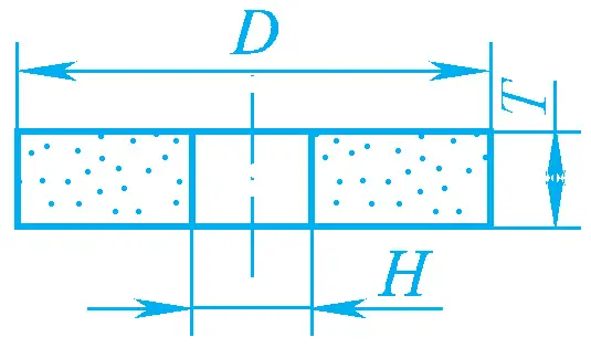 | 1 | 3~90 100~1100 | 1~20 20~350 | 2~63 6~500 | Grinding external diameters, internal holes, centerless grinding, surface grinding, and tool sharpening |
| Straight cutting wheel | 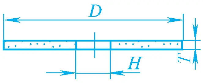 | 41 | 50~400 | 6~127 | 0.2~5 | Cutting and grooving |
| Double-sided concave No. 1 grinding wheel | 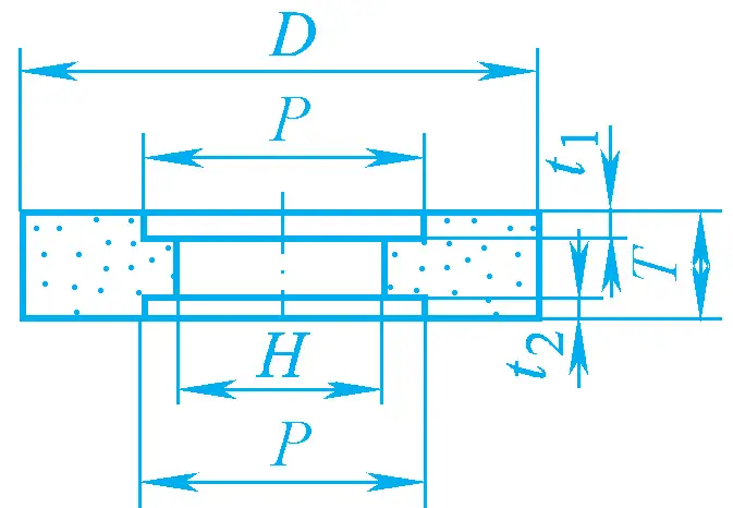 | 7 | 200~900 | 75~ 305 | 50~400 | Grinding external diameters, wheels and guide wheels for centerless grinding, and sharpening the back of turning tools |
| Double bevel edge grinding wheel | 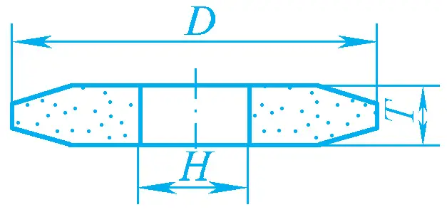 | 4 | 125~500 | 20~ 305 | 8~32 | Grinding gears and threads |
| Cylindrical grinding wheel | 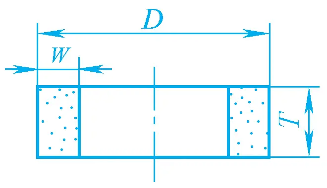 | 2 | 250~600 | W= 25 ~ 100 | 75~ 150 | Grinding flat surfaces |
| Cup-shaped grinding wheel | 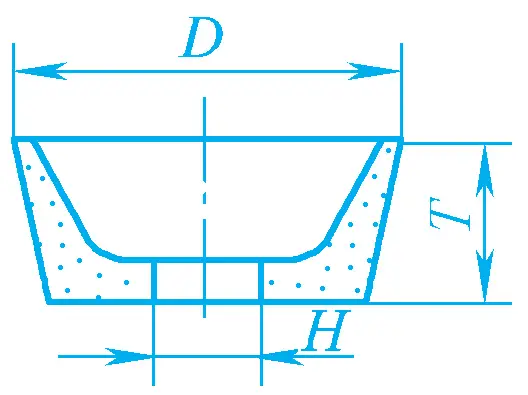 | 11 | 100~300 | 20 ~ 140 | 30~150 | Grinding flat surfaces Grinding the back of cutting tools |
| Disc-shaped grinding wheel | 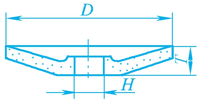 | 12b | 75 100~800 | 13 20~400 | 8 10~35 | Grinding the front of cutting tools |
The markings are printed on the end face of the grinding wheel, in the order of: shape code, size, abrasive, grit number, hardness, structure number, binder, maximum operating linear speed.
For example, a parallel grinding wheel with an outer diameter of 300mm, thickness of 50mm, bore diameter of 75mm, brown corundum, grit size 60, hardness L, structure number 5, ceramic binder, and a maximum operating linear speed of 35m/s, would be marked as:
Grinding wheel 1-300×50×75—A/F60-L-5 V-35m/s
Before installing a grinding wheel, an external inspection should be performed, followed by tapping to listen for any sounds that indicate cracks, to prevent the wheel from bursting at high speeds.
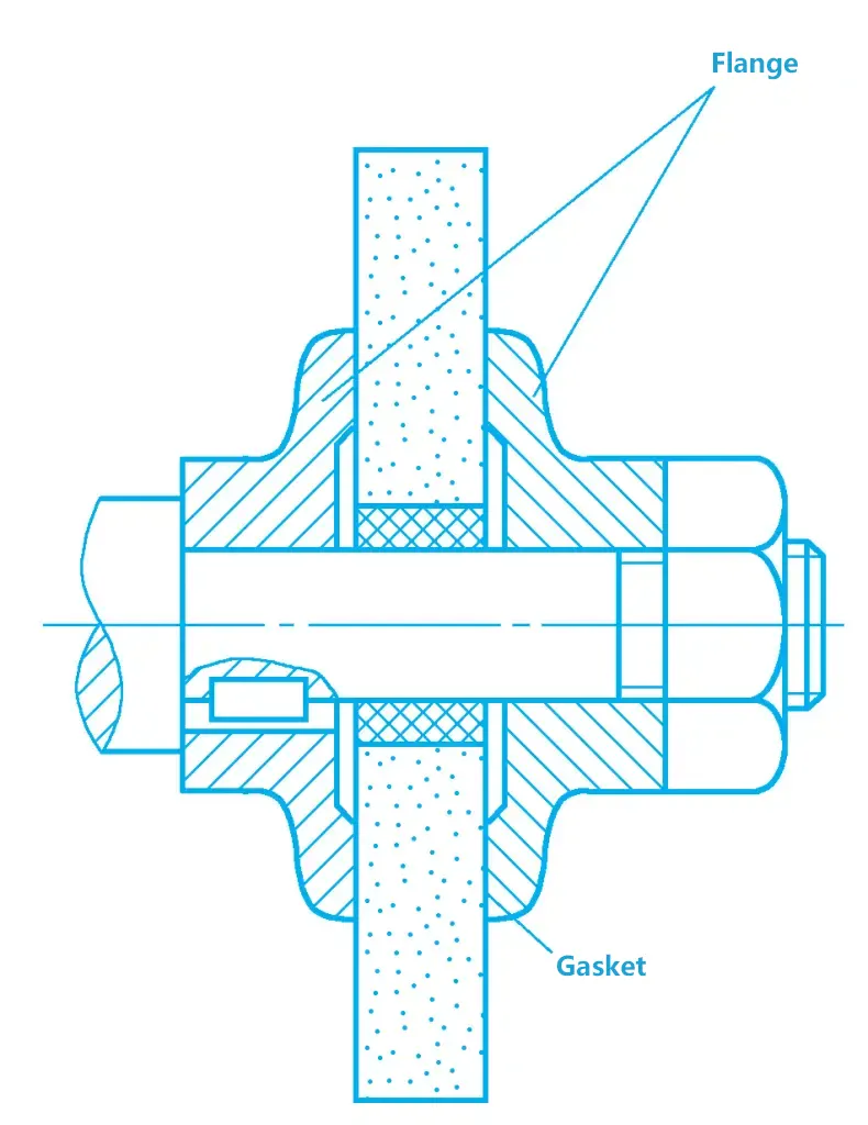
Due to different shapes and sizes, there are different methods for installing grinding wheels. When a grinding wheel is mounted directly on the spindle, the clearance between the inner hole of the grinding wheel and the shaft should be appropriate, generally between 0.1 to 0.8 mm.
The grinding wheel is fastened with a flange plate and nuts, with a leather or oil-resistant rubber gasket, 0.3~3mm thick, placed between the grinding wheel and the flange plate, as shown in Figure 5. Large bore parallel grinding wheels can be first mounted with a stepped flange plate, then installed on the grinding machine spindle.
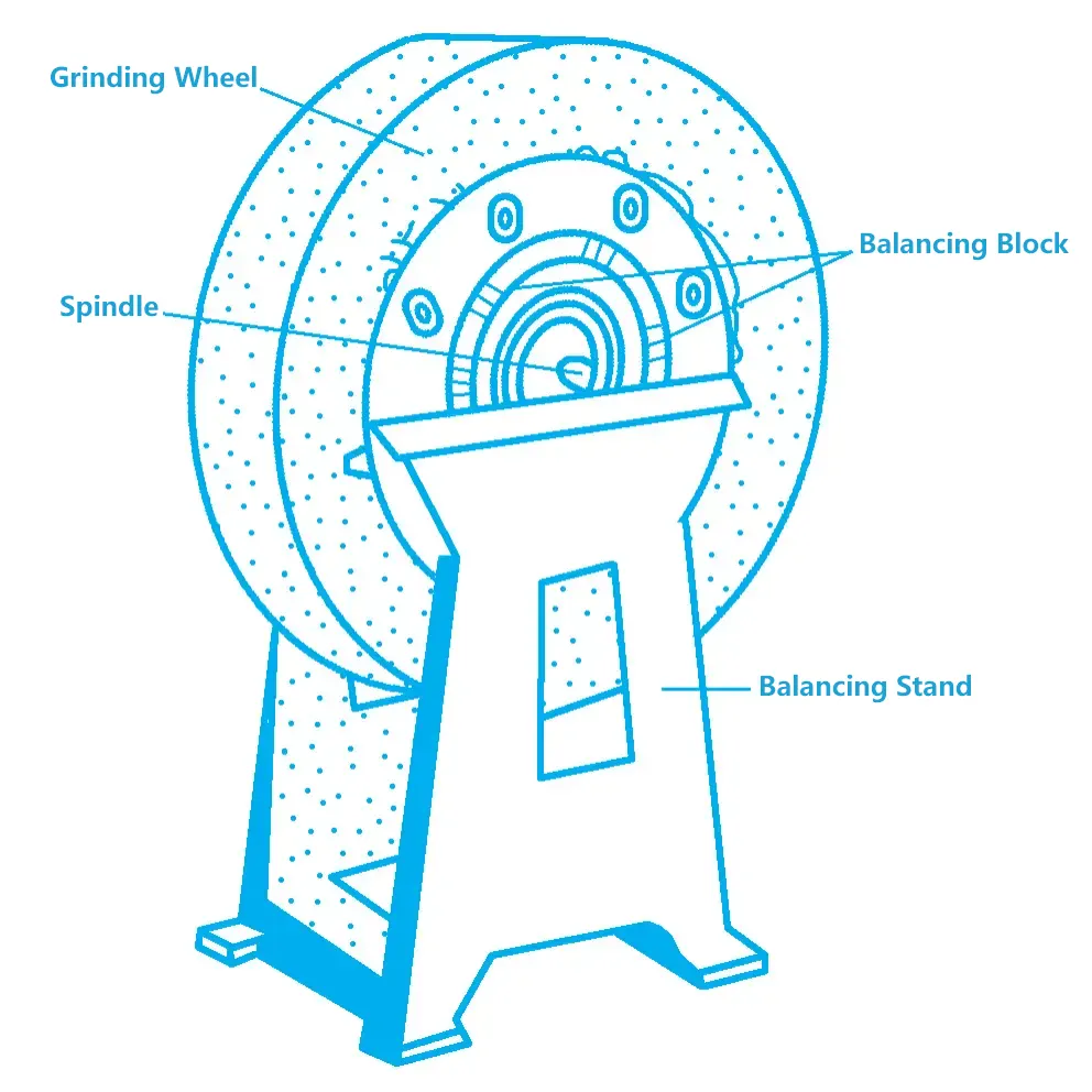
To ensure smooth operation and minimal vibration of the grinding wheel, generally, wheels with a diameter of 125mm or more require static balance adjustment. The specific method is: mount the grinding wheel on the mandrel, then place it on the balance frame guide rail. If it is unbalanced, the heavier part will always rotate to the bottom. At this point, the balance blocks in the annular groove on the end face of the flange can be moved and adjusted repeatedly until the grinding wheel can remain stationary at any position on the guide rail, as shown in Figure 6.
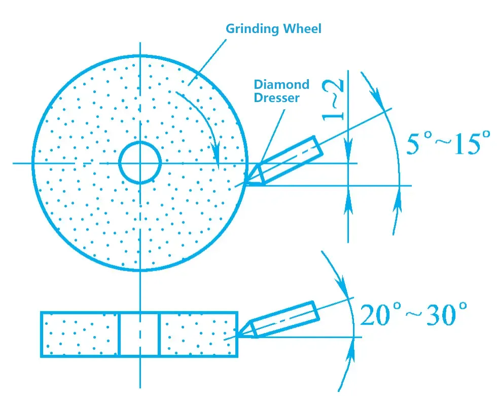
After a period of use, the abrasive grains of a grinding wheel become dull, the surface pores of the wheel become clogged, and the geometric shape of the wheel becomes inaccurate, leading to a decline in grinding quality and productivity. At this time, the wheel needs to be dressed. During dressing, the diamond dresser should be inclined at 5°~15° to the horizontal plane and 20°~30° to the vertical plane, with the tip of the diamond dresser 1~2mm below the center of the grinding wheel, as shown in Figure 7.
External cylindrical grinding uses the outer circumferential surface of the grinding wheel to grind the external rotating surface of the workpiece. It can process cylindrical surfaces, end faces (step parts), as well as spherical surfaces and special-shaped external surfaces. External cylindrical grinding is generally performed on external cylindrical grinding machines or centerless grinding machines, and can also be done using a belt grinding machine.
1) Clamping of the workpiece
On an external cylindrical grinding machine, the workpiece can generally be clamped using the following methods.
① Clamping the workpiece with two centers. The workpiece is supported by the front and rear centers, and the workpiece is rotated by the dog engaged with the faceplate, achieving circumferential feed motion. This clamping method helps improve the rotational accuracy and spindle rigidity of the workpiece, known as the “dead center” working method. Its characteristics include convenient clamping, high positioning accuracy, and the machined surface is easy to obtain higher roundness and coaxiality accuracy.
② Clamping the workpiece with a three-jaw self-centering chuck or a four-jaw independent chuck. On an external cylindrical grinding machine, a three-jaw self-centering chuck can be used to clamp cylindrical workpieces, and other automatic centering fixtures are also suitable for clamping cylindrical workpieces. A four-jaw independent chuck is generally used to clamp irregular workpieces.
③ Clamping the workpiece with a mandrel. When grinding sleeve-type workpieces, the inner hole can be used as the positioning reference to clamp on the mandrel.
④ Use a chuck and a center to clamp the workpiece. When the workpiece is long, one end can be drilled with a center hole, and the other end cannot, then one end can be clamped with a chuck, and the other end with a center.
2)Cylindrical grinding methods
Common cylindrical grinding methods include longitudinal grinding, transverse grinding, segmental grinding, and deep grinding.
① Longitudinal grinding method
As shown in Figure 8a, during grinding, the workpiece performs a circumferential feed motion, and at the same time, it moves longitudinally with the worktable. After each longitudinal stroke or reciprocating stroke, the grinding wheel feeds transversely once, and the remaining amount is ground off after multiple feeds. The efficiency of longitudinal grinding is low, but it can achieve higher precision and lower surface roughness values.
a) Longitudinal grinding method
b) Transverse grinding method
② Transverse grinding method
Also known as the plunge grinding method, as shown in Figure 8b. During grinding, the grinding wheel performs continuous or intermittent transverse feed motion, and the workpiece performs a circumferential feed motion. The width of the grinding wheel is greater than the length of the workpiece surface being ground, the grinding wheel feeds slowly transversely until the required size is reached. The efficiency of transverse grinding is high, but the grinding force is large, the grinding temperature is high, and sufficient cutting fluid must be provided for cooling.
③ Segmental grinding method
Also known as the comprehensive grinding method, it is a combination of longitudinal grinding and transverse grinding, that is, first using the transverse grinding method to coarsely grind the workpiece in segments, leaving a fine grinding allowance for each segment, with a certain amount of overlap between adjacent segments, and finally, using the longitudinal grinding method for fine grinding. The segmental grinding method combines the high efficiency of transverse grinding and the good quality of longitudinal grinding.
④ Deep grinding method
Its characteristic is that all the remaining amount is ground off in one longitudinal feed. During grinding, the grinding wheel is dressed to have a conical or stepped end (see Figure 9), and both the circumferential feed speed of the workpiece and the longitudinal feed speed are very slow. This method has higher productivity, but the dressing of the grinding wheel is complex, and the structure of the workpiece must ensure that there is enough length for the grinding wheel to cut in and out.
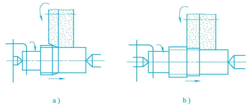
a) Conical wheel grinding
b) Stepped grinding wheel grinding
As shown in Figure 10, the workpiece is placed on the support plate between the grinding wheel and the guide wheel, with the surface to be machined as the positioning reference, without the need for positioning center holes. The workpiece is pushed towards the grinding wheel by the guide wheel (which has no cutting ability and a higher friction factor resin or rubber bonded wheel), and the friction between the guide wheel and the workpiece causes the workpiece to rotate. Changing the speed of the guide wheel can adjust the circumferential feed speed of the workpiece.
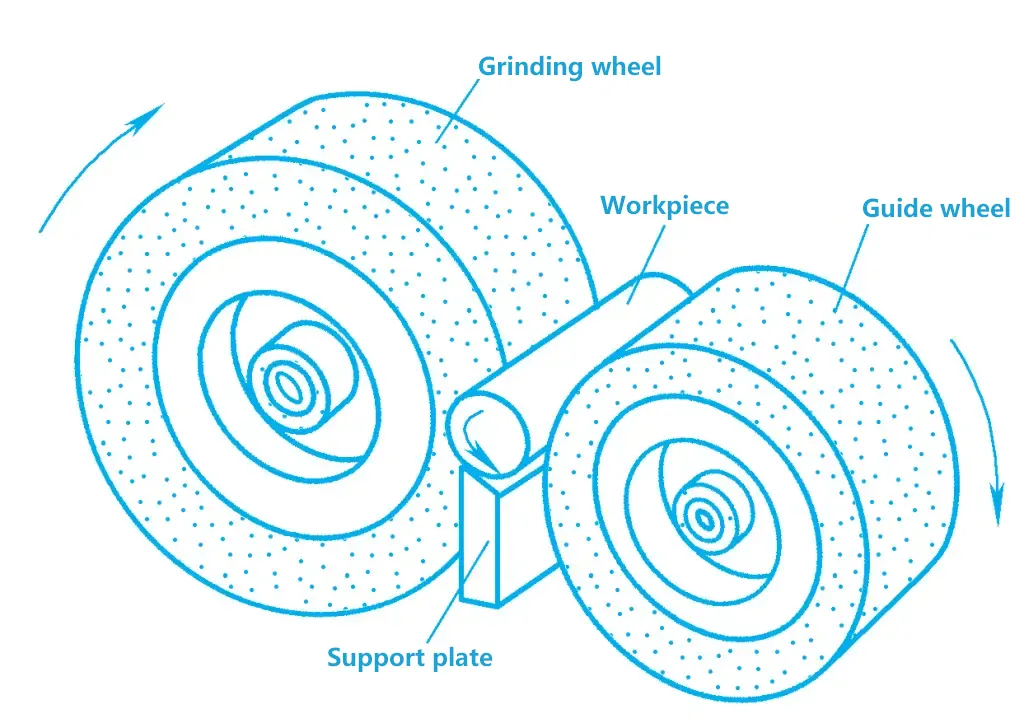
Using centerless cylindrical grinding, the workpiece is easy and quick to load and unload, productivity is high, and automation is easy to achieve. The machining tolerance level can reach IT6, and the surface roughness value is Ra1.25~0.32μm. However, centerless grinding does not easily ensure the positional accuracy between related surfaces of the workpiece, nor can it be used to grind shaft-like workpieces with keyways or notches.
In addition, the outer diameter can also be ground with a belt grinder. Belt grinding is a new type of grinding method, using a high-speed moving abrasive belt as the cutting tool for grinding. The abrasive belt consists of a base, a binder, and abrasive grains, as shown in Figure 11.
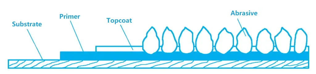
Common base materials are kraft paper, cloth (twill cloth, nylon fiber, polyester fiber, etc.), and paper-cloth combinations. Paper-based abrasive belts are flat, producing workpieces with small surface roughness values; cloth-based abrasive belts have a large carrying capacity; paper-cloth based is between the two.
The binder (usually resin) has two layers, after electrostatic sand planting, the abrasive grains are glued outward on the bottom glue, dried, and then coated with a certain thickness of complex glue to fix the position between the abrasive grains, thus making the abrasive belt. The abrasive belt has only one layer of uniformly graded abrasive grains, making the cutting tool have good uniformity, and the machining quality is better.
Grinding the inner hole of the workpiece with a grinding wheel is called internal grinding, which can be done on a specialized internal grinding machine, or on a universal cylindrical grinding machine equipped with an internal grinding head. Internal grinding can be divided into ordinary internal grinding, centerless internal grinding, and planetary internal grinding methods.
On an ordinary internal grinding machine, grinding the inner hole of the workpiece (see Figure 12), the grinding wheel rotates at high speed as the main motion no, the workpiece rotates for circumferential feed motion nw, at the same time, the grinding wheel or workpiece moves back and forth along its axis for longitudinal feed motion fa, and the grinding wheel also performs radial feed motion fp.
a) Longitudinal grinding of internal holes
b) Cut-in method for grinding internal holes
c) Grinding end faces
Compared with external cylindrical grinding, due to the limitation of the diameter of the hole being processed, both the grinding wheel and the grinding wheel shaft are relatively small in diameter. To achieve the required grinding wheel speed, it is necessary to increase the speed of the grinding wheel spindle, but this can easily cause vibration, affecting the surface quality of the workpiece.
Moreover, because the grinding wheel has a large contact area with the workpiece during internal grinding, resulting in concentrated heat generation, poor cooling conditions, and significant thermal deformation of the workpiece, especially since the grinding wheel spindle has poor rigidity and is prone to bending and deformation, the machining accuracy of internal grinding is not as high as that of external grinding. In actual production, measures such as reducing the lateral feed amount and increasing the number of polishing passes are often used to improve the quality of internal hole machining.
There are four common methods of surface grinding, as shown in Figure 13. The workpiece is clamped on a rectangular or circular worktable with an electromagnetic chuck and makes longitudinal reciprocating linear motion or circular feed motion. Due to the limitation of the grinding wheel width, the grinding wheel needs to make a lateral feed motion along the axis direction. To gradually remove all the excess material, the grinding wheel also needs to periodically feed in a direction perpendicular to the surface being ground.
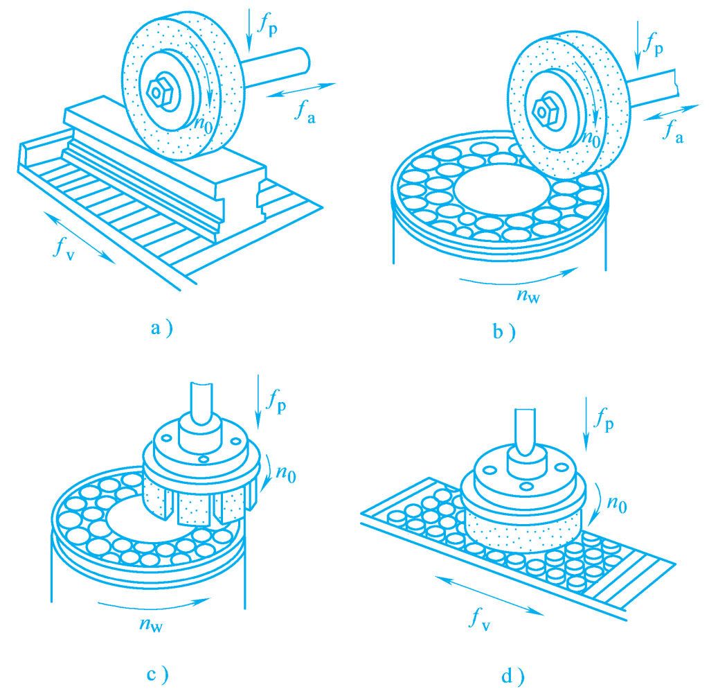
a) Horizontal spindle rectangular table surface grinding
b) Horizontal spindle rotary table surface grinding
c) Vertical spindle rotary table surface grinding
d) Vertical spindle rectangular table surface grinding
Figures 13a and 13b belong to circumferential grinding. In this case, the contact area between the grinding wheel and the workpiece is small, the grinding force is small, the chip removal and cooling conditions are good, the thermal deformation of the workpiece is small, and the wear of the grinding wheel is uniform, so the machining accuracy is relatively high. However, the grinding wheel spindle is in a cantilever state, with poor rigidity, and cannot use a large grinding amount, hence the productivity is low.
Figures 13c and 13d belong to end face grinding, where the grinding wheel has a large contact area with the workpiece, and more abrasive grains participate in the grinding at the same time. Additionally, the spindle is under pressure, which is relatively rigid, allowing the use of a larger grinding amount, hence the productivity is high.
However, during the grinding process, the grinding force is large, the heat generation is significant, the cooling conditions are poor, the chip removal is not smooth, causing large thermal deformation of the workpiece, and the end face of the grinding wheel has unequal linear speeds at different radial points, resulting in uneven wear of the grinding wheel, so the machining accuracy of this grinding method is not high.