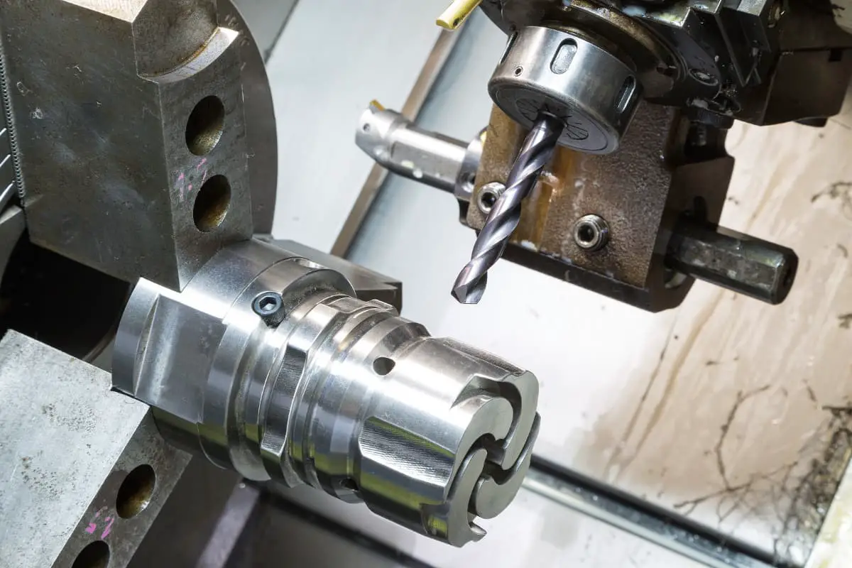
During the processes of connection and assembly of sheet metal parts, it is often necessary to connect two or more metal components using holes or threaded holes, or to assemble positioning holes, etc. For this purpose, tools such as drills and taps must be used on the sheet metal parts to complete the processing of holes or threads. Hole processing and thread processing are basic operations in sheet metal work.
I. Equipment and Tools for Hole Processing
1. Hole Processing Equipment
Commonly used hole processing equipment includes desktop drilling machines, vertical drilling machines, radial drilling machines, and electric hand drills, as shown in Figure 1.

a) Desktop Drilling Machine
b) Vertical Drilling Machine
c) Radial Drilling Machine
d) Electric Hand Drill
a) In the Figure:
1—Motor
2—Spindle
3—Pulley
4—V-Belt
5—Handle
b) In the Figure:
1—Spindle Gearbox
2—Spindle
3—Feed Mechanism
4—Worktable
5—Column
6—Handle
c) In the Figure:
1—Base
2—Worktable
3—Spindle Box
4—Column
5—Radial Arm
6—Spindle
d) In the Figure:
1—Motor
2—Pinion
3—Spindle
4—Drill Chuck
5—Large Gear
6—Gear
7—Front Housing
8—Rear Housing
9—Switch
10—Electrical Wire
(1) Desktop Drilling Machine
Bench drilling machine, referred to as bench drill, is a small drilling machine, generally used for holes with a diameter below 12mm.
(2) Vertical drilling machine
Vertical drilling machine, referred to as vertical drill, is generally used to drill holes on medium-sized workpieces. Its maximum drilling diameters are 25mm, 35mm, 40mm, and 50mm in several specifications.
(3) Radial drilling machine
The spindle speed range and feed rate of the radial drilling machine are relatively large, and it has a wide range of applications. It can be used for drilling, reaming, and reboring various types of holes.
(4) Hand electric drill
A hand electric drill is a portable electric tool. When assembling large workpieces, if the shape of the workpiece or the location of machining restricts the use of a drilling machine, a hand electric drill can be used.
The voltage of hand electric drills is divided into single-phase (220V, 36V) or three-phase (380V). The specifications for drills using single-phase voltage are 6mm, 10mm, 13mm, 19mm, and 23mm. For three-phase voltage drills, available specification includes 13mm.
19mm, 23mm, three types.
2. Drilling tools
Drill bits are the main tools for drilling. There are many types, with commonly used ones including center drills and twist drills.
(1) Center drill
Center drills are specifically used to drill center holes on the end face of the workpiece, mainly for positioning parts for machining using the center holes on the workpiece end face or for centering before using a twist drill. There are two shapes: a regular center drill and a double-cone center drill with a 120° protective cone, as shown in Figure 2.

a) Center drill for machining regular center holes
b) Center drill for machining double-cone center holes
(2) Twist drill
The twist drill is named after its working part’s shape, which resembles a twist. It is the most widely used drilling tool in production, capable of drilling holes from φ0.1 to φ80mm. Figure 3 shows the structure of a twist drill. A standard twist drill consists of a shank, neck, and working part. The working part is the main body of the drill bit, comprising the cutting part and the guiding part.
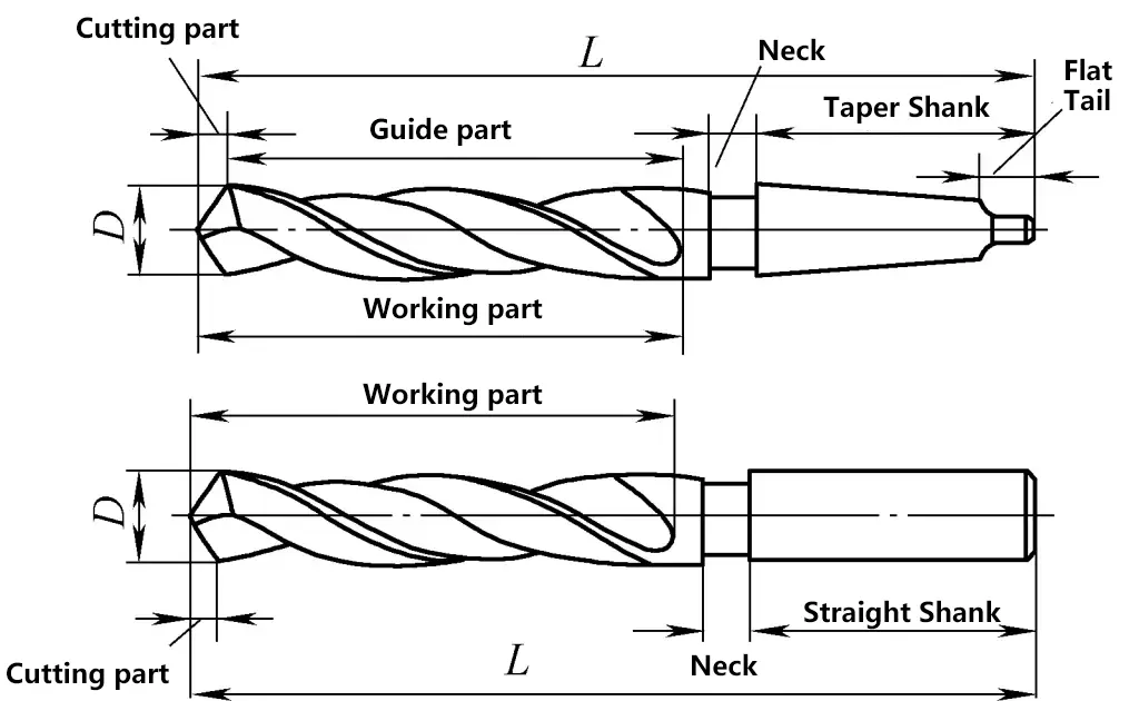
The cutting part is responsible for the main cutting tasks and includes two main cutting edges, two secondary cutting edges, and a chisel edge. The guiding part, consisting of the spiral groove, margin, and back, guides the cutting direction of the drill bit.
Twist drills are mostly made of high-speed steel (high alloy tool steel). Long drill bits with a diameter greater than 8mm are sometimes made in a welded form, using high-speed steel for the working part and 45 steel for the shank.
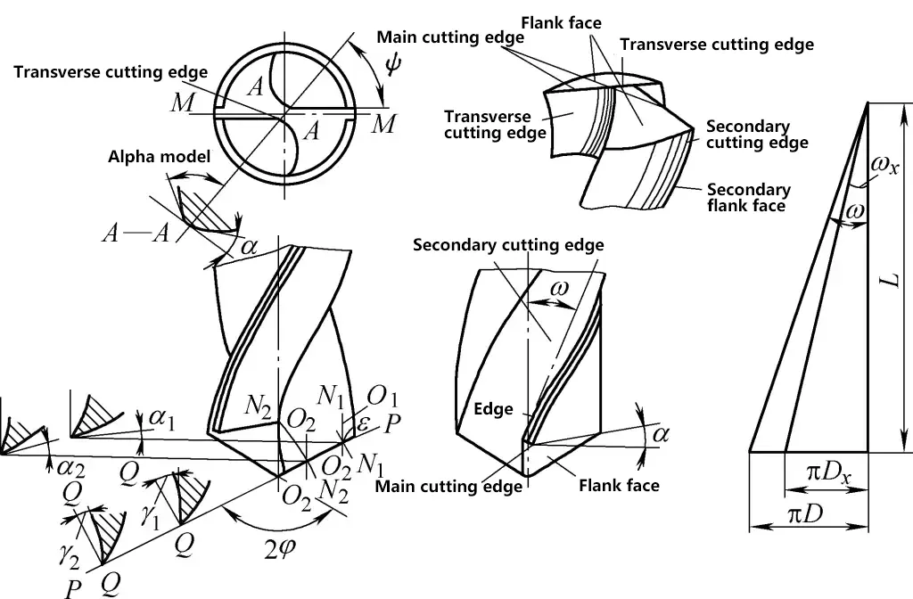
The geometric angles of the cutting part of a twist drill include the helix angle (ω), the rake angle (γ), the clearance angle (α), the point angle (2φ), and the chisel edge angle (ψ). These geometric parameters are shown in Figure 4.
II. Drilling techniques
Drilling relies on drilling equipment and drill bits to complete. During drilling, the workpiece is fixed, and the drill bit is mounted on the spindle of the drilling machine for rotational motion, referred to as the main movement (v). Simultaneously, the drill bit moves along the axial direction, known as the feed movement (S), as shown in Figure 5.
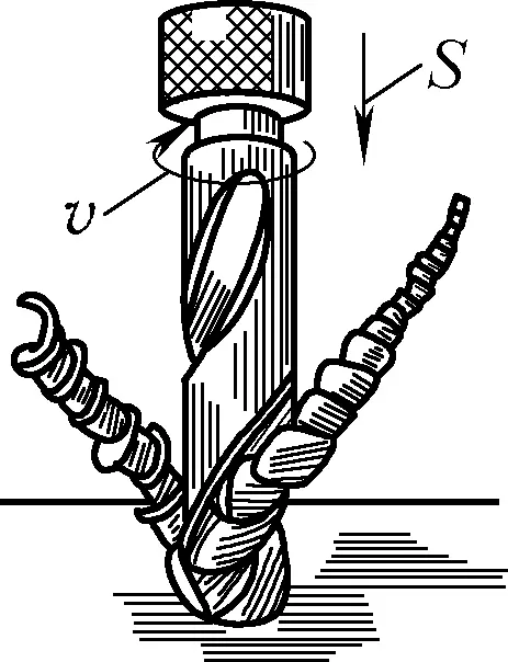
Drilling is considered rough machining for holes, with an accuracy of IT11 to IT13 and a surface roughness Ra of 50 to 12.5μm, making it suitable only for holes with low precision requirements. For higher precision holes, reaming can be used, which generally achieves an accuracy of IT9 to IT7 and a surface roughness Ra of 3.2 to 0.8μm.
1. Drilling steps
Drilling operations can generally follow these steps:
1) Scribing before drilling.
Before drilling, cross center lines of the hole positions must be scribed according to position and size requirements, and center punch marks should be made. The punch marks should be small and precisely located, with circular lines for the hole diameter scribed.
For larger diameter holes, several inspection circles or boxes symmetrical to the hole center line can be scribed as shown in Figure 6. Then, enlarge the center punch marks to prepare for lowering the drill and centering.
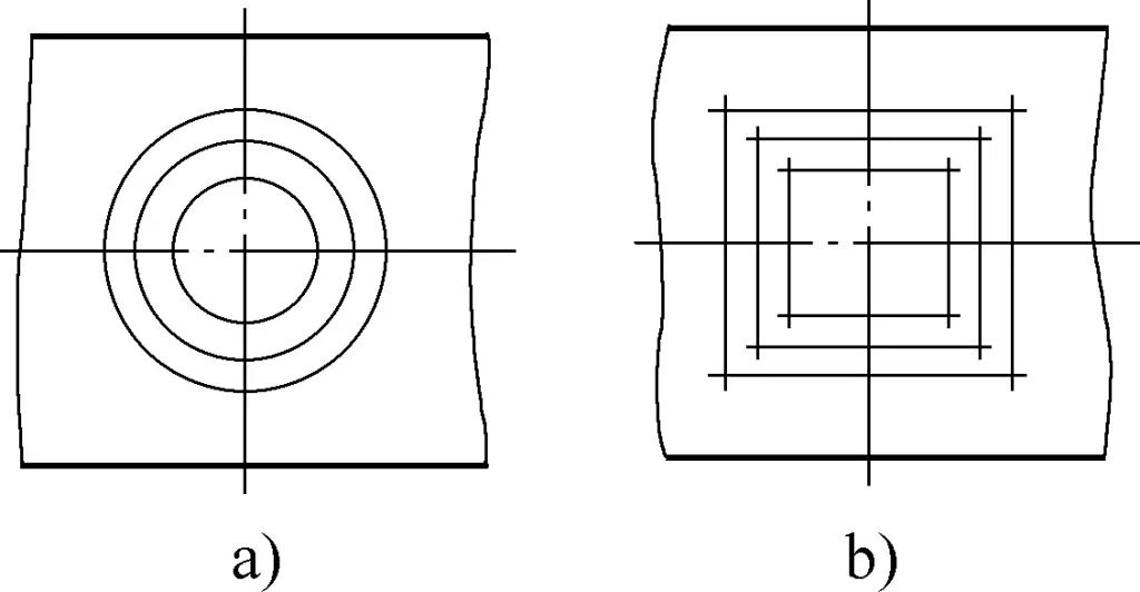
a) Inspection circles
b) Inspection boxes
2) Clamping the workpiece.
Securely fixing the workpiece during drilling is very important. Otherwise, the workpiece may be rotated with the drill bit, possibly damaging the workpiece and the drilling machine, as well as posing a safety hazard. Various clamping methods can be used depending on the size of the workpiece, as shown in Figure 7.
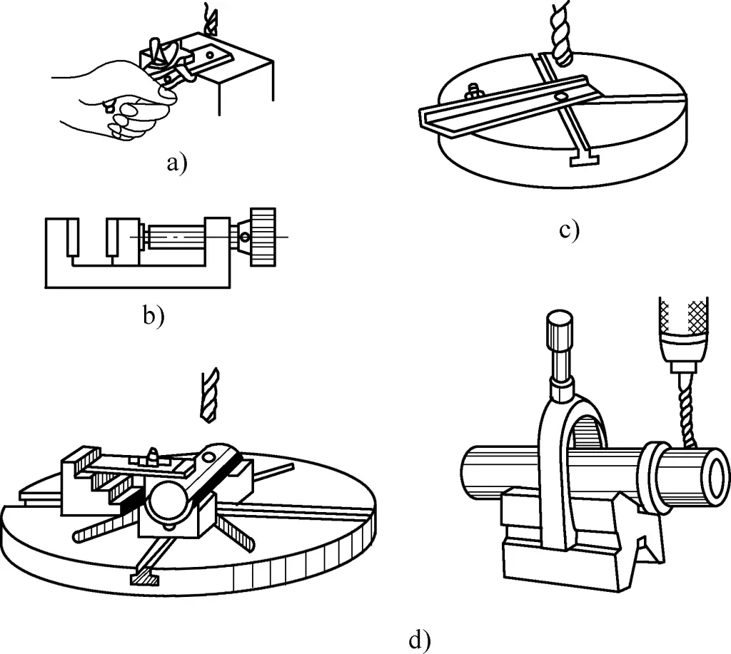
a) Clamping with a bench vise
b) Clamping with a small machine vise
c) Anti-rotation with screws
d) Clamping with plate bolts
In bench or vertical drilling machines, hand vises, plain vises, and bench vises can generally be used for clamping. For drilling long workpieces, they can be held by hand and the workpiece can be supported (anti-rotation) with screws. Cylindrical pieces can be clamped on a V-block. Larger workpieces can be directly clamped on the worktable with plate bolts.
3) Holding the drill bit.
Holding the drill bit is done using special fixtures. Figure 8 illustrates the scenario of holding a straight-shank drill bit with a drill chuck.
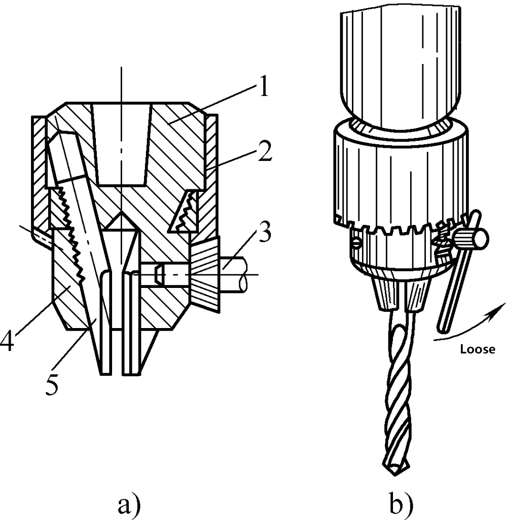
a) Drill chuck structure
b) Drill chuck working conditions
1—Chuck body
2—Chuck sleeve
3—Key
4—Ring nut
5—Jaw
When holding the drill bit, first insert the shank into the three jaws 5 of the drill chuck, and the clamping length should not be less than 15mm. Then use the special key 3 for the drill chuck to rotate the chuck sleeve 2, so that the ring nut 4 drives the three jaws to move along the inclined surface, allowing the jaws to open or close simultaneously, thereby achieving the purpose of loosening or tightening the drill bit.
4) Pre-drilling inspection.
Before drilling, verify the machining drawing, check the correctness of the drilling position and drill bit size, the firmness of the workpiece holding, etc., and adjust the drill press speed accordingly.
5) Drilling.
After the pre-drilling inspection is qualified, drilling can be carried out, ensuring safe operation.
6) Cleaning after drilling.
After a hole is processed, clean the work surface promptly to prepare for subsequent workpieces or another location’s hole processing. After all workpieces are drilled, clean the drill press promptly and dismantle and store the drill bit properly.
2. Key points of drilling operation
The main points of drilling operations include the following aspects:
1) Drilling methods.
For general workpieces, the following methods can be used during drilling:
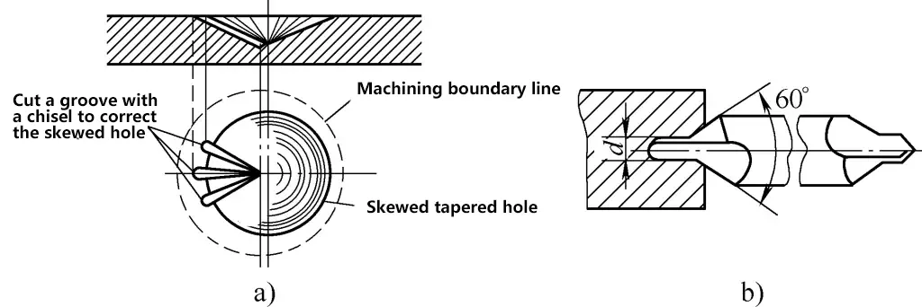
First aim at the center punch indentation and pre-drill a shallow conical pit. If the drilled conical pit is not concentric with the drilling line circle, the workpiece or drill press spindle can be moved to correct it. When the deviation is large, use a center punch to re-punch or use a chisel to cut out several slots for correction, as shown in Figure 9.
a) Correcting hole deviation via chisel slots
b) Using center drill to guide hole centering for large holes
When drilling larger holes, because of the long chisel edge of large-diameter drill bits making centering difficult, it is best to first drill a larger conical pit with a center drill, as shown in Figure 9b, or use a short twist drill with a small point angle (2φ=90°~100°) to drill a conical pit. After the test drill achieves concentricity requirements, the workpiece or drill press spindle must be refastened before re-drilling.
When drilling through-holes, use manual feed and proceed gently until the drill breaks through. Extra care should be taken with thin workpieces.
When drilling blind holes, check the depth accuracy via drill bit length and actual measurement. On unprocessed surfaces or harder material, start with manual feed.
Drill holes with a diameter greater than 30mm in two steps. Use a drill bit with 0.5~0.7 times the hole diameter first, then expand to the required diameter.
When drilling small holes with diameters less than 4mm, use manual feed only, initially take care to prevent drill bit slippage, and avoid applying too much pressure to prevent bending and breaking. Lift the drill bit occasionally to clear chips.
When drilling deep holes (hole depth to diameter ratio greater than 3), use a small feed rate, and lift the drill bit regularly to clear chips, preventing chip blockage and drill bit breakage or damage to the inner hole surface.
2) Selection of cutting fluid.
During drilling, due to friction between the drill bit and the workpiece and chip deformation, high heat is generated, leading to the main cutting edge of the drill bit becoming annealed and losing cutting capacity, quickly dulling the drill bit. To lower the working temperature of the drill bit, extend its service life, improve drilling productivity, and ensure drilling quality, adequate cutting fluid must be injected during drilling.
Drilling generally belongs to rough machining processes, with the primary purpose of using cutting fluid for cooling. Common cutting fluids used in drilling are listed in Table 1.
Table 1 Common Cutting Fluids for Drilling
| Workpiece material | Cutting fluid |
| Structural steel | Emulsion, engine oil |
| Tool steel | Emulsion, engine oil |
| Stainless steel, heat-resistant steel | Linseed oil aqueous solution, sulfurized cutting oil |
| Pure copper | Emulsion, vegetable oil |
| Aluminum alloy | Emulsion, kerosene |
| Chilled cast iron | Kerosene |
| Cast iron, brass, bronze, magnesium alloy | Not used |
| Hard rubber, glue | Not used |
| Plexiglas | Emulsion, kerosene |
3) Selection of cutting parameters.
The cutting parameters during drilling refer to the cutting speed, feed rate, and cutting depth while drilling. The cutting speed (v) is the linear speed at a point on the drill diameter (m/min). The feed rate (f) refers to the distance the drill moves downward per revolution (mm/r). The cutting depth (ap) during drilling equals the drill radius (mm), i.e., ap=D/2.
Only the cutting speed (v) and feed rate (f) need to be selected during drilling. These two parameters are mostly chosen based on experience.
Generally, when drilling with a small diameter drill, the speed should be faster, and the feed rate should be smaller. When drilling large holes with a large diameter drill, the speed should be slower, and the feed rate can be relatively larger. When drilling hard materials, the speed should be slower, and the feed rate smaller. When drilling soft materials, the speed can be faster, and the feed rate larger.
3. Drilling methods
When drilling holes in different sheet metal components, it is necessary to adopt different drilling methods accordingly.
1) Drilling holes in cylindrical workpieces.
To drill a hole perpendicular to the axis through the center of the cylinder on parts like shafts or sleeves, use a centering tool (typically V-block) to clamp the drill press spindle before drilling. Align the drill press spindle center with the V-block center, and secure the V-block position with a clamp. Place the cylindrical workpiece horizontally in the V-block, adjust it to a level position, align the drill bit with the drilling center, and secure the workpiece tightly before test drilling and drilling the hole.
If alignment work is done carefully, the symmetry between the hole center and the workpiece centerline can be controlled within 0.1mm.
2) Drilling inclined holes.
There are three scenarios for drilling inclined holes: drilling holes on an inclined surface, drilling inclined holes on a flat surface, and drilling holes on a curved surface. They all share a common feature: the hole center is not perpendicular to the drilling end surface.
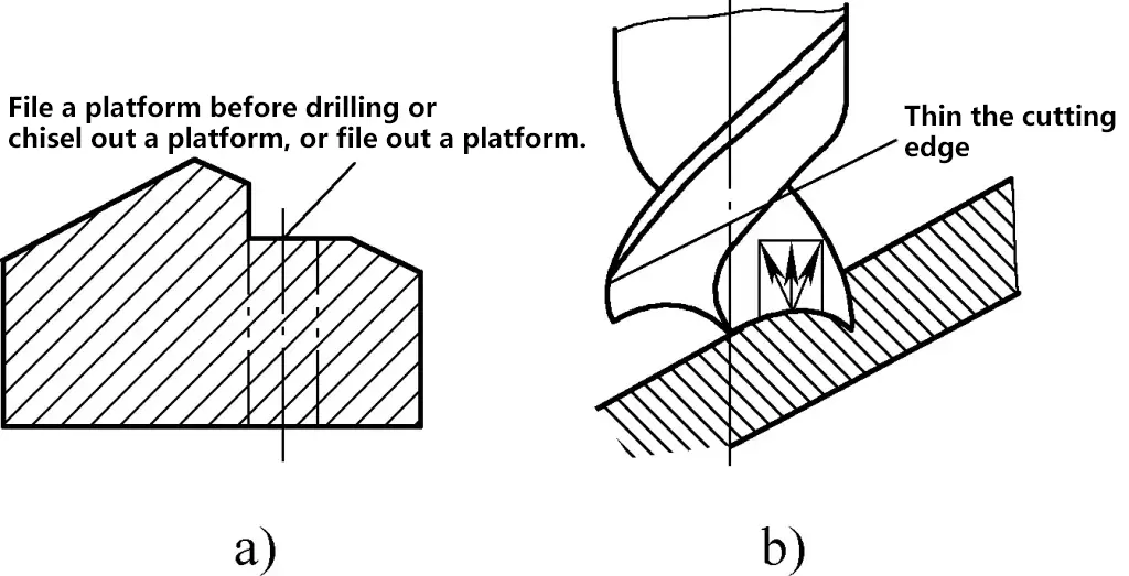
While drilling, chisel or file out a platform at the drilling entry point, or mill out a platform with an end mill (see Figure 10a). First, use a small diameter drill or center drill to drill a shallow hole or recess. Once properly positioned, drill the hole. Three equal height pointed drills can be used to drill inclined holes as well (see Figure 10b).
3) Drilling semi-circular holes.
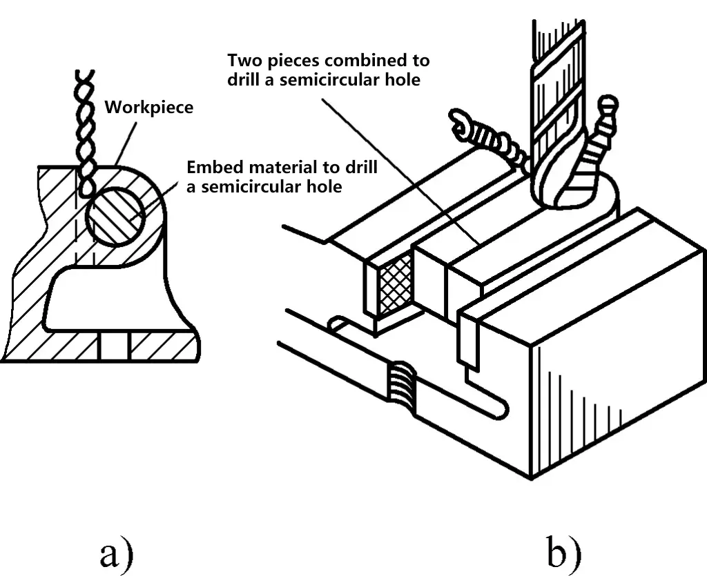
When drilling semi-circular holes, as one side of the drill bit encounters a backing force, it deflects to the other side, causing the bit to bend or break, resulting in non-perpendicular holes. To prevent this from happening, for semi-circular holes at the edge of the workpiece, join two identical workpieces together for drilling. For external semi-circular holes, use the same material to fill in and then drill, as shown in Figure 11.
a) Insert material
b) Merge two pieces
When drilling split line screw holes and the materials on both sides of the seam have different hardness, use a stiff drill bit (preferably short). The center punch mark should be slightly biased towards the harder material side. Once the bit has drilled to a certain depth and is biased towards the softer side contact point, align the bit with the contact point to continue drilling.
4) Drilling tandem holes.
Common types of tandem holes are shown in Figure 12. Due to the depth or distance between the two holes, the drill bit extends long during drilling, causing vibration, difficulty in centering, and propensity to bend, leading to tilted holes with poor concentricity.

The following methods can be used for drilling: for tandem holes shown in Figure 12a, first use a short drill bit to drill a small hole to the depth of the large hole, then switch to a long small drill bit to finish drilling the small hole, then drill the large hole and countersink the large hole bottom plane.
For tandem holes shown in Figure 12b, first drill the top hole, then use a tightly fitting large punch to insert into the top hole to punch the mark for the bottom hole. Drill a shallow recess slowly with the drill bit centered on the punch mark, confirm accuracy, then drill at high speed.
For tandem holes shown in Figure 12c, for mass production, a long drill rod can be made with an outer diameter fitting the top hole loosely. Drill the top large hole first, then switch to the long drill rod fitted with a small bit. Use the top hole as a guide to drill the bottom small hole. Alternatively, use the method for tandem holes shown in Figure 12b.
4. Drill bit grinding
The purpose of grinding drill bits is to resharpen or repair the cutting edge that has dull or damaged, or to reshape the drill bit to fit specific material needs, ensuring good drilling performance.
The accuracy of drill bit grinding directly affects the drilling quality, efficiency, and drill bit lifespan. Manual grinding of drill bits is done on a bench grinder. The common grit used is 46-80. During grinding wheel rotation, the run-out must be strictly controlled. Grinding methods mainly include:
(1) Grinding of the main cutting edge
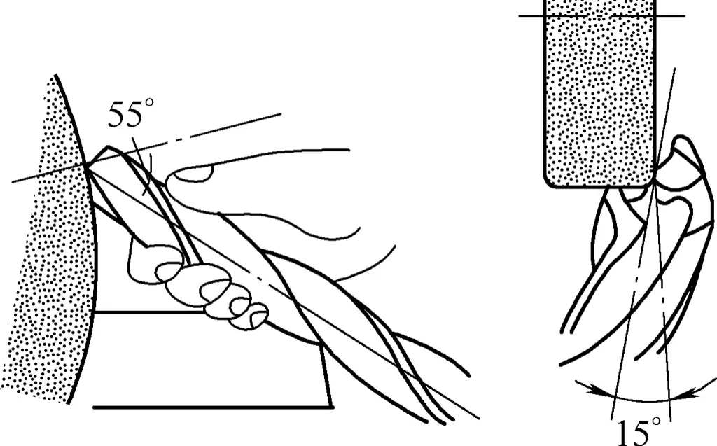
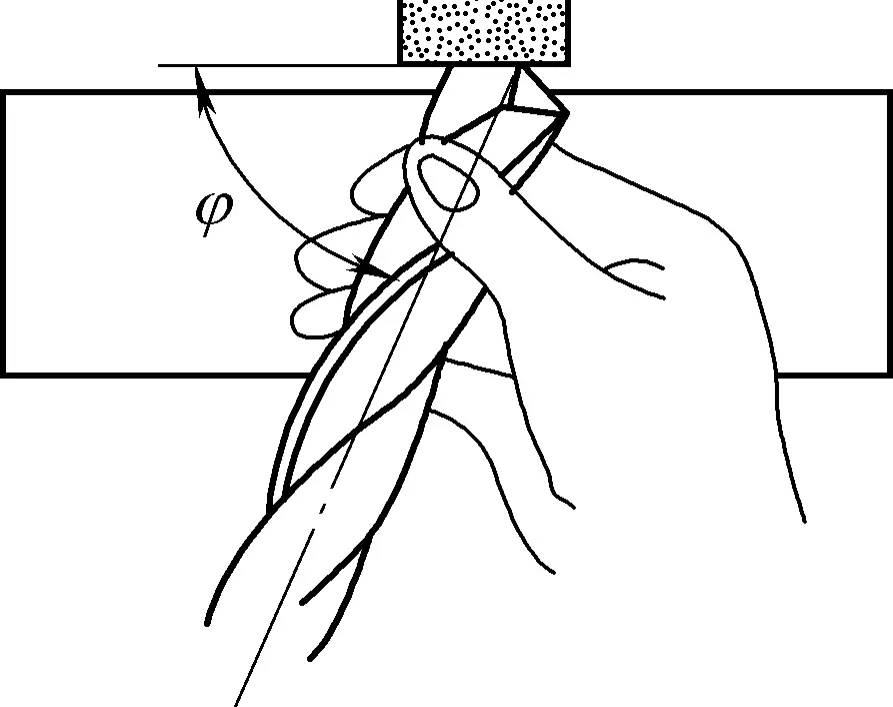
During grinding, use the right hand (or left hand) to hold the drill bit’s head as a positioning pivot (or rest it on the grinder bracket), and the other hand to hold the drill shank. Align the drill bit axis and the grinder cylindrical surface at an angle φ and tilt 8°~15° downward, ensuring the main cutting edge is horizontal and lightly touches the circumference above the grinder center line.
Apply pressure with the hand holding the drill head towards the grinder and fix the rotational position of the drill bit around its axis. The hand holding the shank rotates the drill bit clockwise around its axis while oscillating up and down. Rotating the drill bit around its axis ensures the entire flank face is ground, while the up and down movement grinds the required clearance angle.
Hand movements must be well-coordinated. The oscillation angle varies with the clearance angle, as the clearance angle differs at various radii of the drill bit. Repeat this process a few times. After grinding one main cutting edge, rotate 180° to grind the other main cutting edge. This shapes the chisel angle, clearance angle, and web thinning angle, as shown in Figure 13.
The specific value of the drill bit point angle 2φ can be selected according to different drilling materials as shown in Table 2.
Table 2 Drill Bit Tip Angle Selection [Unit: (°)]
| Material to be processed | Tip Angle (2φ) |
| Steel and Cast Iron (Medium Hard) | 116~118 |
| Manganese Steel | 136~150 |
| Hard Aluminum Alloy | 90~100 |
| Steel Forgings | 125 |
| Brass and Bronze | 130~140 |
| Plastic Products | 80~90 |
After sharpening the main cutting edges, check if the tip angle 2φ bisects the drill’s axis, whether both main cutting edges are symmetrical and equal in length, and each is a straight line. Also, check if the back angle at the outer edge of the main cutting edges complies with the required value and if the chisel edge angle is accurate.
(2) Sharpening the Chisel Edge
When sharpening the chisel edge, the relative positions of the drill and the grinding wheel are as shown in Figure 14. During sharpening, first make the back of the edge contact the grinding wheel, then rotate the drill so that the grinding point gradually moves toward the center of the drill to shorten the chisel edge. The edge of the grinding wheel used for sharpening the chisel edge should have a small curve, and the diameter of the grinding wheel is preferably also smaller.
