Lathe Tool Essentials: Classifications & Sharpening Tips
This blog explores the classifications of lathe tools and provides essential tips on how to sharpen them effectively. You'll learn…
Imagine a tool so precise it can shape a hole with perfection. This is the essence of hole turning, a fundamental technique in mechanical engineering. In this article, you’ll explore the basics of hole turning, from its principles to practical applications. Get ready to understand how this process can enhance the accuracy and efficiency of your machining projects.
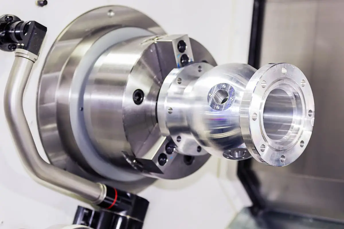
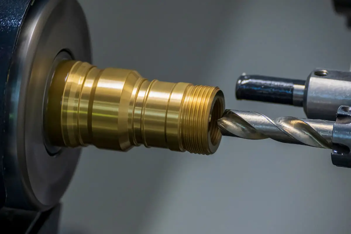
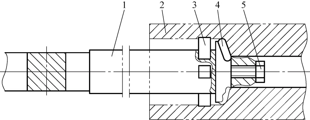
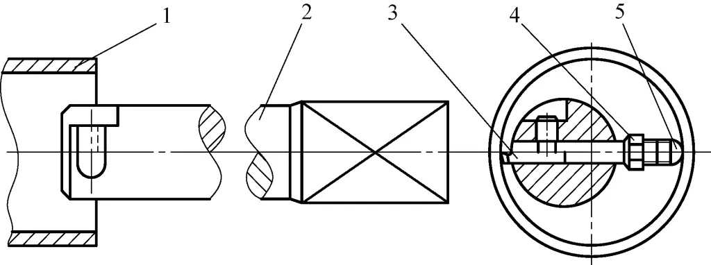
Turning ordinary hole-type workpieces on a lathe is shown in Figure 2-137.
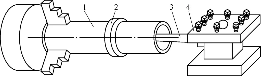
1—Anti-vibration ring
2—Workpiece
3—Boring tool holder
4—Tool post
Due to different boring conditions and workpiece materials, the geometric angles of the selected boring tools also differ.
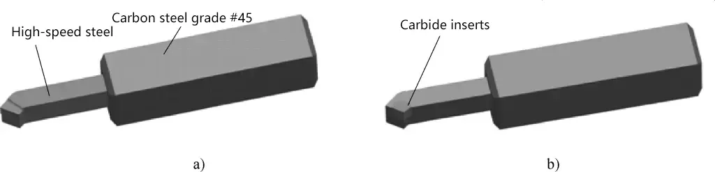
Figure 2 shows the boring tools used for turning internal holes in hardened steel (hardness 55-60HRC), Figure 2a shows a rough boring tool, and Figure 2b shows a finishing boring tool. The tool insert material is YT30 carbide, and the tool holder material is 45 quality carbon steel, with a hardness of 35-45HRC after quenching.
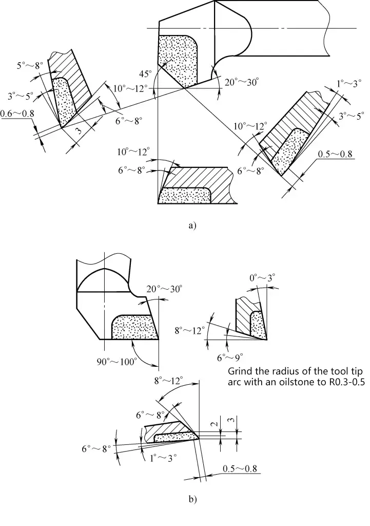
a) Rough boring tool
b) Finishing boring tool
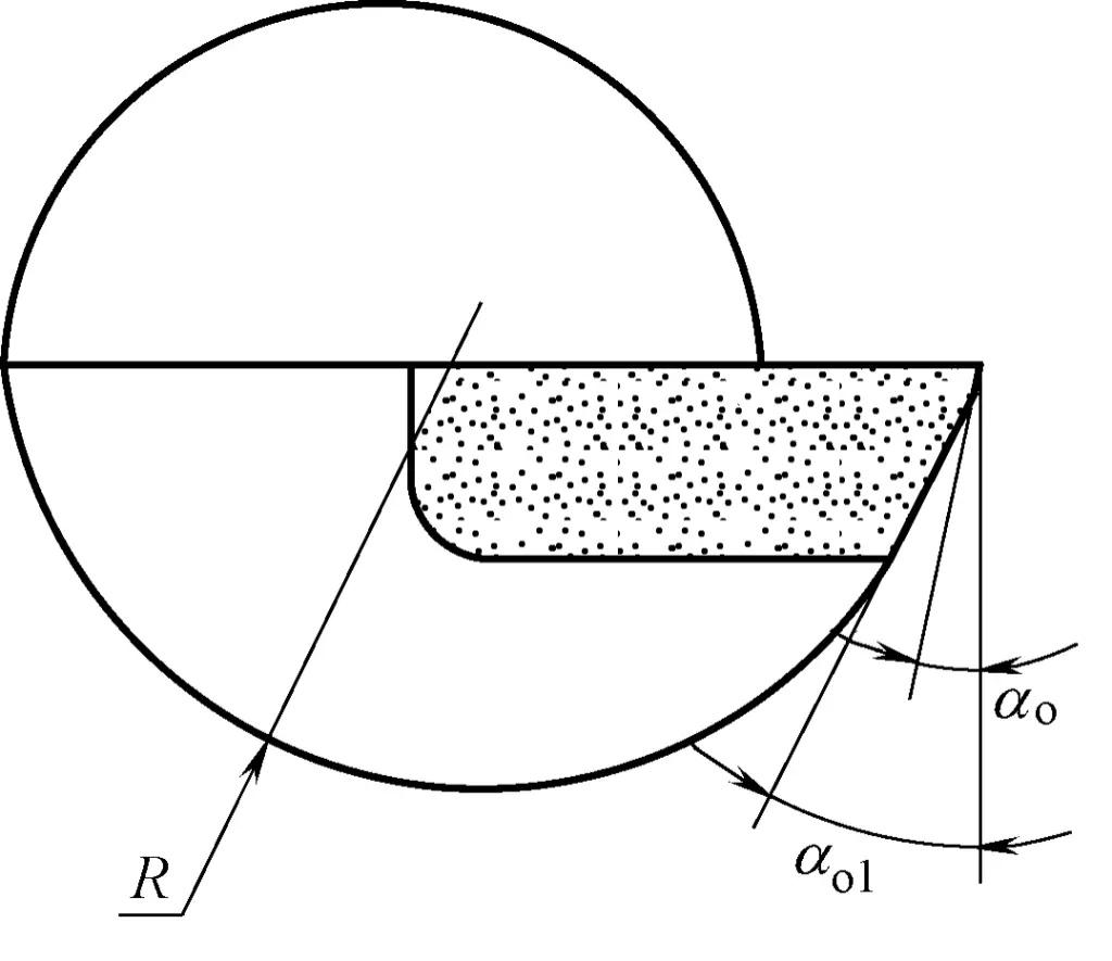
The surface roughness Ra value at the cutting edge of the finishing boring tool is 0.4μm. When boring small holes, if the bottom surface of the tool holder contacts and rubs against the inner hole surface, the bottom of the tool holder can be ground into an R-shaped circular form, as shown in Figure 3.
The cutting parameters used are as follows. Since the workpiece to be turned is hardened steel material, the cutting speed v should be lower. For rough boring, v=8-12m/min; for finish boring, v=12-16m/min. For rough boring, f=0.1-0.15mm/r; for finish boring, f=0.05-0.1mm/r. For rough boring, the back cutting depth a should not exceed 0.05mm. Cutting fluid is not used.
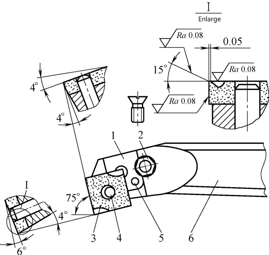
1—Insert clamping block
2—Clamping screw
3—Insert
4—Cylindrical pin
5—Pivot pin
6—Tool shank
Figure 6 shows a machine-clamped thin-walled tube boring tool, with a rake angle γ=15°, main cutting edge angle K=75°, chip breaker groove width of 2mm, and front face surface roughness Ra value <0.8μm. When boring, cutting is smooth and quick, with chips appearing silver-white. The selected cutting parameters are: cutting speed v=80m/min, feed rate f=0.1mm/r.
The geometry of the boring tool for high-speed turning of cast holes is shown in Figure 5. It uses YG type carbide inserts. The cutting edge consists of a 4mm long main cutting edge, a 1mm long intermediate edge, and a polishing edge with a width of 1.2f (f is the feed rate). The main cutting edge is used for rough machining, the intermediate edge for semi-finishing, and the polishing edge for polishing the already turned inner hole surface.
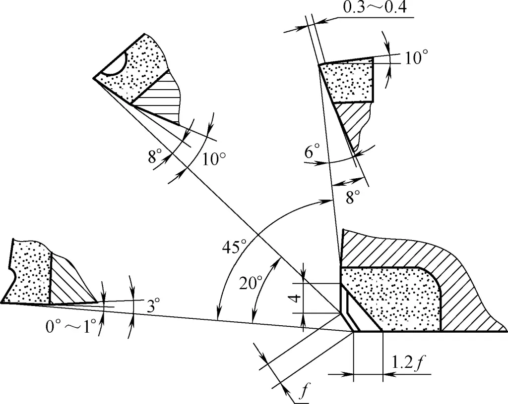
This boring tool has a rake angle γ=10°, clearance angle α=8°, but the clearance angle of the polishing edge is only 1°. If it rubs against the hole wall during boring, the bottom surface of the tool can be ground round. The cutting parameters used are: cutting speed v=200m/min, feed rate f=0.5mm/r.
Figure 6 shows a high-power boring tool with a broken-line cutting edge, using YT15 carbide inserts. This boring tool is very effective when used on CA6140 horizontal lathes and medium-sized lathes for turning short, thick internal holes with diameters of 60-150mm in steel workpieces.
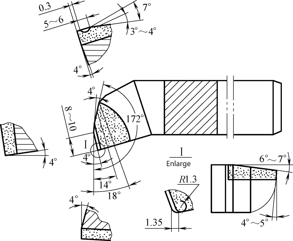
This boring tool uses unequal rake angles, and the main cutting edge is in a broken-line shape. During boring, the left and right edges are subjected to forces, properly balancing and offsetting the cutting forces, reducing the radial cutting force, and making the cutting process more stable. The main cutting edge forms angles with the chip breaker platform and chip discharge inclined surface, improving chip evacuation and enabling natural chip breaking.
The main cutting edge angle is a double main angle, and the angle is relatively large. Compared to general boring tools, it adds a 172° tool tip wedge angle, and is ground with a negative chamfer and tool tip radius, improving tool strength and extending service life. The tool holder material is 45 quality carbon steel. As it is a high-power boring tool, the tool holder dimensions should be appropriately larger to increase rigidity and reduce vibration.
The cutting parameters used are: cutting speed v=140-150m/min; back cutting depth a=12-15mm; feed rate f=0.3-0.5mm/r.
When installing, this boring tool should be 1.5-2mm higher than the workpiece center.
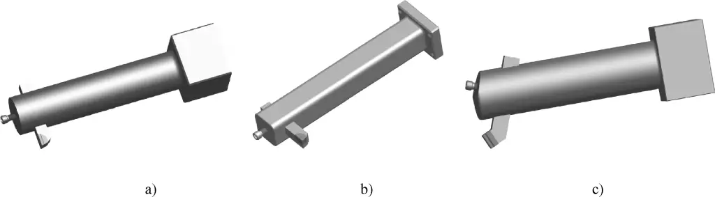
For large-scale production, to improve efficiency and ensure boring quality, the boring tool shown in Figure 7 can also be used. This is a high-efficiency boring tool that can be used when machining allowance is large or when turning long holes with uneven machining allowance.
Its structure is a tool insert-style cutter with a double-edged tool head. Four alloy support blocks are evenly welded to the back of the tool head, with the outer diameter of the alloy support blocks being about 0.04mm smaller than the inner diameter of the hole being bored by the tool head.
1—Tool holder
2—Workpiece
3—Alloy support block
4—Double-edged boring tool head
5—Fastening screw
During machining, the tool shank is clamped onto the tool holder, with its axis aligned with the center of rotation. When boring, the double-edged tool head cuts in first, immediately followed by the alloy support block supporting the inner hole.
The outer diameter of the four alloy support blocks should be slightly smaller than the hole diameter bored by the tool head. During the boring process, the alloy support blocks provide support, ensuring the rigidity of the tool shank, while also acting as scrapers to improve the cylindricity of the inner hole and reduce its surface roughness.
When machining long holes or performing large-allowance cutting, the increased machining allowance will widen the chips. In this case, several chip-breaking grooves can be ground behind the main cutting edge to facilitate chip removal and ensure the entry of cutting fluid.
The cutting speed v c of this boring tool is 140m/min, with a feed rate f=0.2mm/r. For workpieces with an allowance of about 40mm, cutting can be completed in one pass.
The structures of lathe tool shanks are diverse, determined by the workpiece conditions and machining requirements. The following introduces over 10 types of boring tool shanks for selection.
As shown in Figure 8, it is forged from a bent steel plate, with a carbide tool tip welded to the tool head for use; alternatively, a high-speed steel material can be integrally forged into the required boring tool shape (without the need for welding the tool head).
a) Integral high-speed steel boring tool
b) Welded boring tool
When boring, use the dial on the cross slide handle to control the depth of cut on the back.
As shown in Figure 9, the tool head and shank of this boring tool are separate. The tool head can be removed by loosening the screw, making tool grinding and replacement convenient.
a) Form I
b) Form II
c) Form III
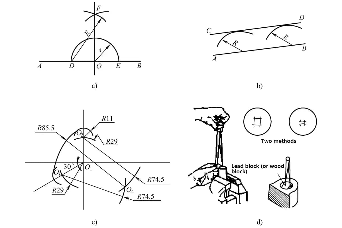
The structure of ordinary boring tool shanks is the simplest. When adjusting the tool head extension length, generally tap the tool head and then use a caliper to measure if the extension length meets the requirements (Figure 10). If not suitable, tap it a couple more times until the hole diameter size can be guaranteed.
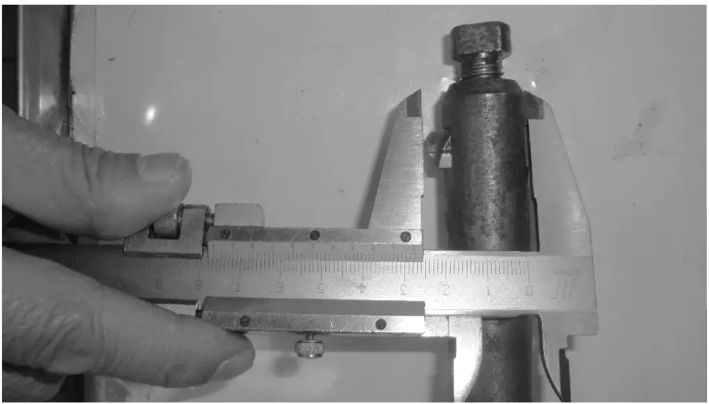
Figure 11a shows the main body of the small hole boring tool shank. When in use, insert the small hole boring tool (Figure 11c) into the hole of the main body and tighten the nut (Figure 11b) to secure the boring tool.
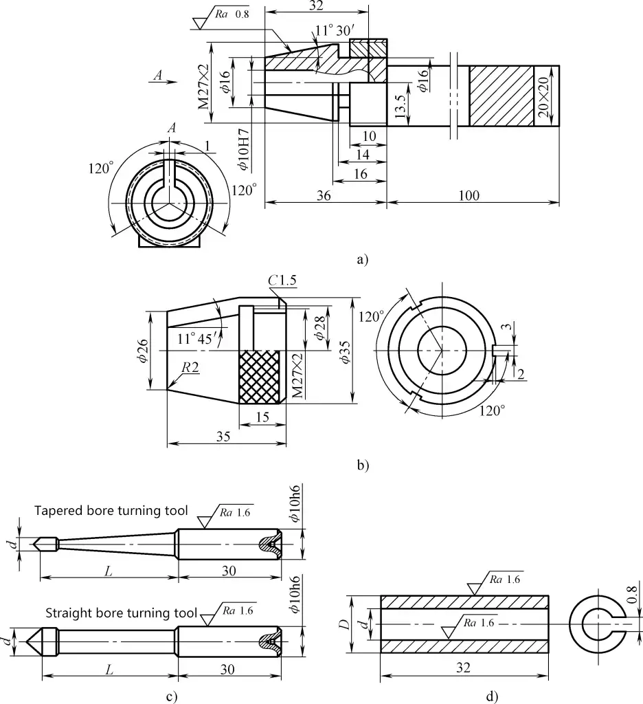
a) Boring tool shank main body
b) Boring tool shank nut
c) Small hole boring tool
d) Open-end socket
When installing the boring tool, use a small bent wrench to hook the open slot on the nut. As the left end of the boring tool shank main body is a hardened elastic body, it can securely clamp the boring tool.
One boring tool shank can be fitted with various specifications of boring tools to meet the processing needs of different diameter small holes. This type of boring tool shank, when used with an open-end socket (Figure 11d), can also hold small-sized center drills, drill bits, reamers, etc., for other forms of machining.
When in use, insert the small tool shank into the tool hole of the boring tool shank and tighten the nut to secure the small tool shank. This type of shank (Figure 12) is very suitable for boring holes with diameters of 20-40mm. Cutting fluid should be used abundantly during cutting.
1—Nut
2—Tool clamp
3—Small tool shank
4—Tool hole
5—Boring tool shank
The boring tool shank with spiral groove allows chips to be discharged along the spiral groove, avoiding chip clogging. To reduce vibration and increase the back depth of cut, the diameter of the tool shank should be appropriately increased during manufacturing. This boring tool shank is suitable for boring through holes and should be used with cutting fluid.
As shown in Figure 13, it rotates around a pin as a pivot. When tightening the left screw and loosening the right screw, the boring diameter increases; when tightening the right screw and loosening the left screw, the boring diameter decreases. Insert the chuck head into the tailstock taper hole or make the handle part of the chuck body conical to insert directly into the tailstock taper hole.
1—Workpiece
2—Boring tool
3—Screw
4—Pin
5—Chuck body
6—Chuck head
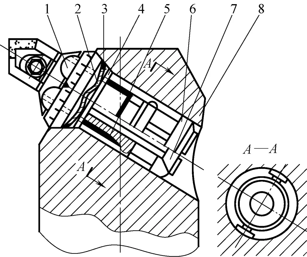
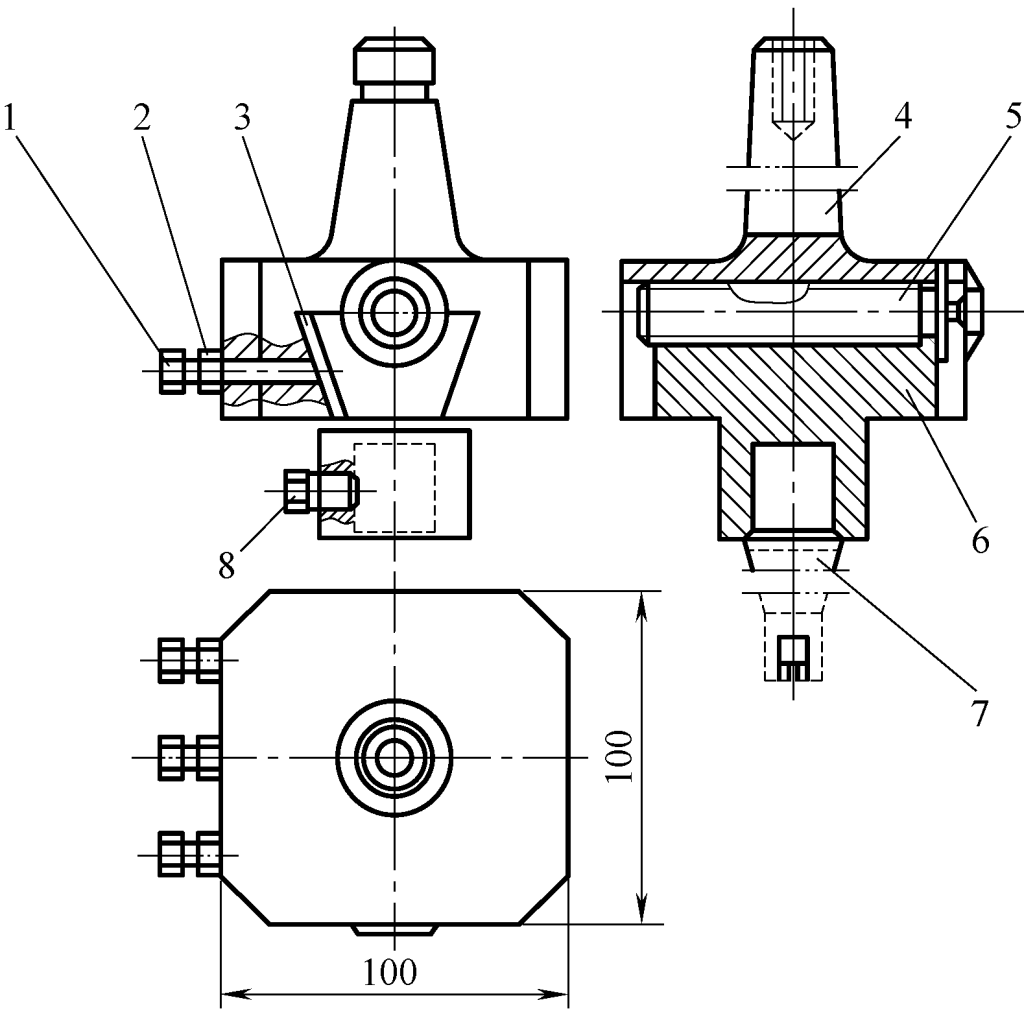
As shown in Figure 14, this boring tool shank uses a square shank form. When in use, insert it into the square hole of the tool body and clamp it with the fixing screw and pivot pressure screw. The pivot pressure screw also acts as a pivot point. During use, turn the adjustment screw to rotate the boring tool shank around the pivot pressure screw by the appropriate angle for fine adjustment.
1—Tool body
2—Fixing screw
3—Pivot pressure screw
4—Boring tool shank
5—Tool head
6—Square iron
7—Connecting block
8—Adjustment screw
This boring tool shank is designed based on the lever principle.
As shown in Figure 15, its main body is connected to the lathe spindle flange. The inner hole of the eccentric sleeve has an eccentricity e from its outer circle (the eccentricity e is determined according to specific situations). To adjust the boring size, loosen the fixing screw and rotate the eccentric sleeve.
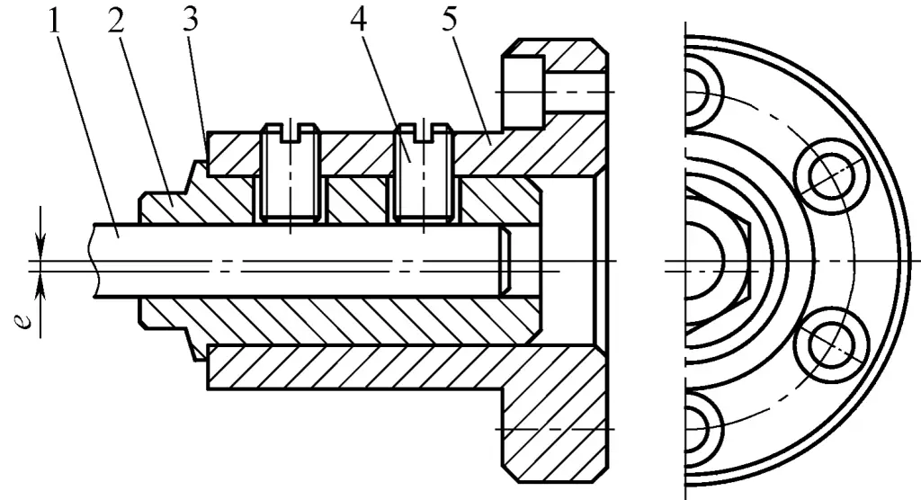
1—Tool shank
2—Eccentric sleeve
3—Scale line
4—Fixing screw
5—Main body
There are scale lines on both the end face of the eccentric sleeve and the main body. The adjustment amount can be seen from the scale lines. After adjustment, tighten the fixing screw. This boring tool shank is suitable for boring relatively small holes.
As shown in Figure 16, there are equally spaced pointed teeth on both the end face of the boring tool shank and the bottom of the tool head, which mesh with each other. Two tool heads, 1 and 2, are installed at 180° to each other at the front end of the boring tool shank.
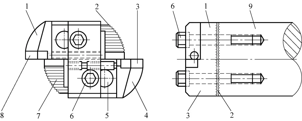
1—Tool head 1
2—Pointed teeth
3—Tool insert 2
4—Tool head 2
5—Tooth groove
6—Screw
7—Boring tool
8—Tool insert 1
9—Boring tool shank
Tool inserts are welded onto the tool head, which has a long slot. To adjust the extension distance of the tool insert, loosen the screw, and the tool head can move radially along the tooth groove. Tighten the screw after adjustment. The pointed teeth should be hardened to have a certain hardness to prevent damage and deformation.
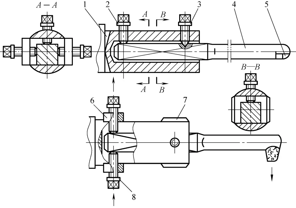
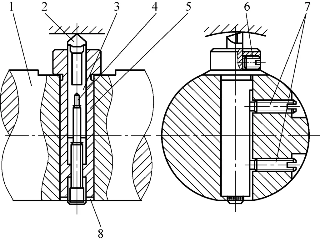
As shown in Figure 17, the boring tool shank 2 is installed in the taper hole of the spindle 1, the tool shank 8 is installed in the threaded hole of the inner cylinder 5, and the outer sleeve 3 is connected to the boring tool shank 2 via threads. The inner cylinder 5 and outer sleeve 3 have a sliding fit.
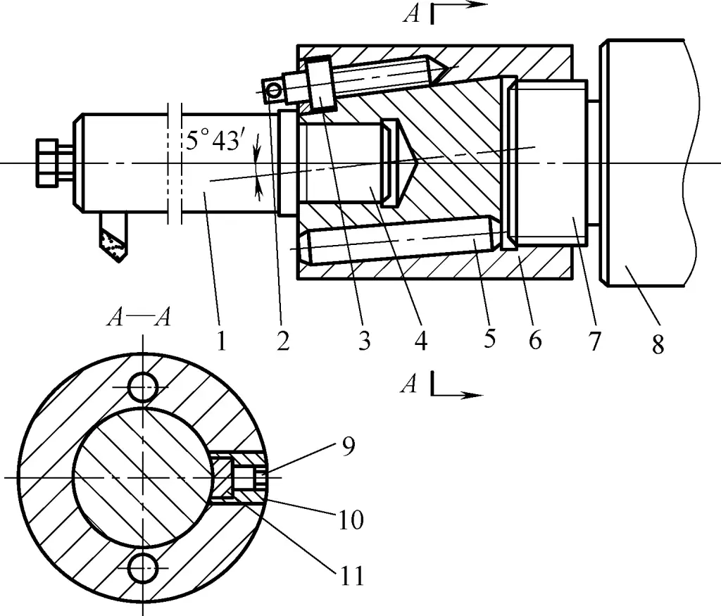
1—Spindle
2—Boring tool shank
3—Outer sleeve
4—Cylindrical pin
5—Inner cylinder
6—Zero ring
7—Fine-tuning screw rod
8—Tool shank
9—Hexagon socket screw
10—Threaded sleeve
11—Brass fixing washer
The centerline of the inner hole of the outer sleeve 3 is inclined at an angle of 5°43′ to the axis of the boring tool shank 2. To adjust the boring tool, first loosen the hexagon socket screw 9, then turn the fine-tuning screw rod 7 to drive the inner cylinder 5 inside the outer sleeve 3 to move radially along the inclined centerline. After adjustment, tighten the hexagon socket screw 9.
The shoulder of the fine-tuning screw rod 7 has equally spaced circular graduations. When its pitch is 1.5mm, one full rotation results in a radial movement a of the cylinder 5 of: 15mm×sin5°43’=1.5mm×0.0996=0.1494mm≈0.15mm. If the fine-tuning screw rod 7 has 30 graduations, then the radial movement for one graduation is a/30=0.1494mm/30≈0.005mm.
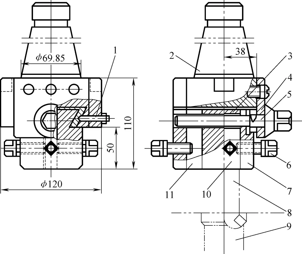
As shown in Figure 18, the oblique hole of this boring tool shank forms a 60° angle with the tool shank axis. The oblique hole has a double keyway and contains a tool clamping screw rod. The double convex key can slide in the double keyway of the oblique hole, with the cylindrical part having a sliding fit with the oblique hole. The circular iron washer is fixed in the oblique hole of the boring tool shank.
The indexing nut is used to adjust the extension distance of the tool head. After adjusting the tool clamping screw rod to the required size, lock the screw and the circular iron washer together. The washer, sealing gasket, and elastic ring are used for dust prevention and damping.
1—Indexing nut
2—Elastic ring
3—Sealing ring
4—Washer
5—Tool clamping screw rod
6—Circular iron washer
7—Screw
8—Boring tool shank
There are graduations on the indexing nut. When the indexing nut rotates one full turn, the tool clamping screw rod moves one pitch. For example: if the thread is M18×1.5, since it is inclined at a 60° angle to the boring tool shank axis, the radial displacement of the tool tip is: 1.5mm×sin60°=1.299~1.33mm. If there are 65 graduations on the indexing nut, then one graduation of rotation of the indexing nut results in a radial displacement of the tool tip of 0.02mm.
As shown in Figure 19, the adjustment direction of the tool head extension for this boring tool shank is perpendicular to the tool shank axis. In the figure, the main body sleeve is mounted on the boring tool shank and fixed with a long screw. The tool head is installed in the tool clamping sleeve hole and tightened with a small screw.
The small end of the screw rod is threaded into the threaded hole of the tool clamping sleeve, and the large end is threaded into the threaded hole of the main body sleeve. The pitches of the large and small ends of the screw rod are different. To adjust, rotate
1 – Boring bar
2 – Tool head
3 – Tool holder sleeve
4 – Threaded rod
5 – Main body sleeve
6 – Small screw
7 – Long screw
8 – Graduated lines
To adjust, first loosen the small screw that secures the tool head. Graduated lines on the threaded rod head allow precise control of the tool head movement.
As shown in Figure 20, the boring tool head on the bar is cylindrical. Turning the fine adjustment screw 6 moves the boring tool head 4 radially along the boring bar. Tightening or loosening the hex socket screw 5 moves sliding blocks 2 and 3 to clamp or release the boring tool head 4.
1—Boring bar
2, 3—Slider
4—Cutting head
5—Hex socket screw
6—Fine adjustment screw
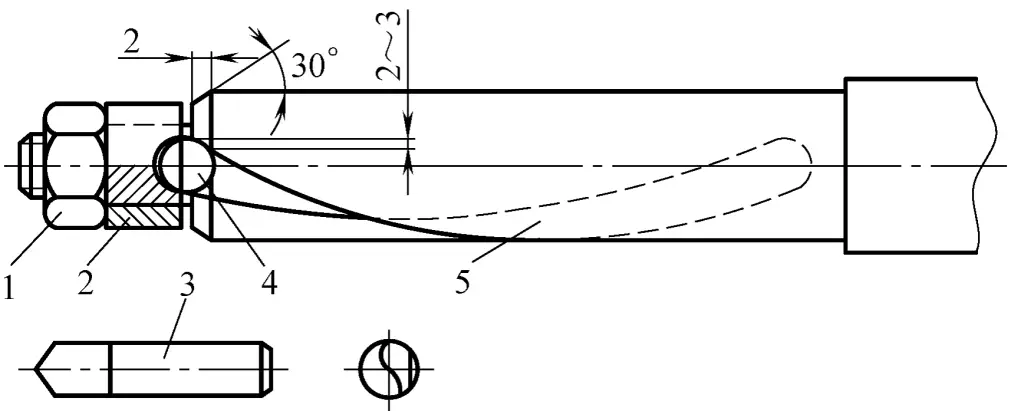
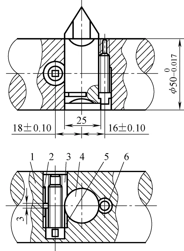
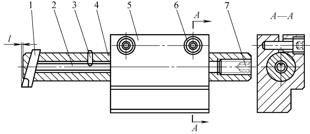
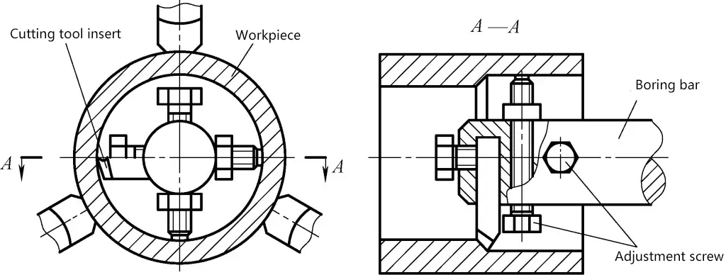
As shown in Figure 21, a square hole is machined transversely at the end of the boring bar. A short high-speed steel boring tool is inserted from each end. The inner end of the short boring tool is ground into a V-shape and fixed with fastening screws. When adjusting the protrusion length of the short boring tool, the adjustment screw at a 45° angle can be turned to push the cylindrical pin forward, moving the short boring tool.
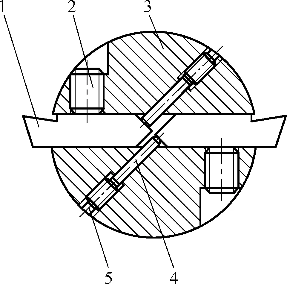
1—Boring tool
2—Fastening screw
3—Boring bar
4—Cylindrical pin
5—Adjustment screw
During boring, the two short boring tools each bear half of the back cutting depth, or one serves as a rough boring tool while the other serves as a fine boring tool.
(Figure 22) When in use, its tapered shank fits with the spindle taper hole. After inserting it into the taper hole, use a drawbar at the rear end of the lathe spindle to pull the boring head, enhancing rigidity and preventing it from detaching. There is a dovetail groove under the tapered shank, with a dovetail block sliding in it. When the lead screw is turned, the dovetail block can move along the dovetail groove, adjusting the rotational diameter of the cutting head.
1—Locking screw
2—Locking nut
3—Adjustment plate
4—Main body
5—Lead screw
6—Dovetail block
7—Boring bar
8—Fixing screw
A graduated dial is installed at one end of the lead screw to control the back cutting depth. The dial has scale lines, with 100 divisions. The thread on the lead screw is M20×2, and each division rotated increases the back cutting depth by 0.02mm. The boring bar is secured with fixing screws. When adjusting dimensions, first loosen the locking screw, then turn the lead screw. After adjustment, tighten the locking screw and the locking nut.
When manufacturing this boring head, ensure that the internal threads on the dovetail block and the main body are machined together to guarantee a tight fit with the lead screw.
Fine-tuning boring bar structures are suitable for boring large diameter holes.
(Figure 23) When turning the lead screw, the square nut moves the dovetail block on the tool holder radially along the dovetail groove, adjusting the rotational diameter of the boring bar. After each adjustment, tighten the nut of the locking screw.
1—Locking screw, nut
2—Tapered shank
3—Square nut
4—Positioning plate
5—Lead screw
6—Screw
7—Tool holder
8—Boring bar
9—Workpiece
10—First tool mounting hole
11—Second tool mounting hole
Two tool mounting holes are made on the tool holder, with different distances from the center of the boring bar’s tapered shank. When boring large holes, install the boring bar in the second mounting hole; for small holes, use the first mounting hole. On the side of each mounting hole, there is one screw (or two can be used) to secure the boring tool.
The lead screw has a rectangular thread with a pitch of 3mm. The tapered dial has 100 equally spaced scale lines. Each mark rotated moves the tool holder by 0.03mm.
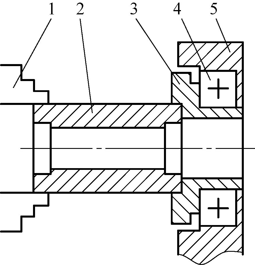
For boring large diameter holes, the large-hole boring bar (also called a combination boring bar) shown in Figure 24 can be used. Remove the small slide of the lathe and install the main body of the large-hole boring bar. Clamp the boring bar in the main body, insert the boring head into the square hole at the left end of the boring bar, tighten the fixing screw, and secure the boring head with the thrust rod. Loosen the hex socket screw to change the protrusion length of the boring bar.
1—Boring head
2—Thrust rod
3—Locating pin
4—Boring bar
5—Main body
6—Hex socket screw
7—Fixing screw
The length of the locating pin extending into the boring bar should allow the thrust rod to move freely inside the boring bar. After adjusting the protrusion length of the boring bar, tighten the hex socket screw.
The main body of the large-hole boring bar is made of cast iron, providing good vibration damping properties.
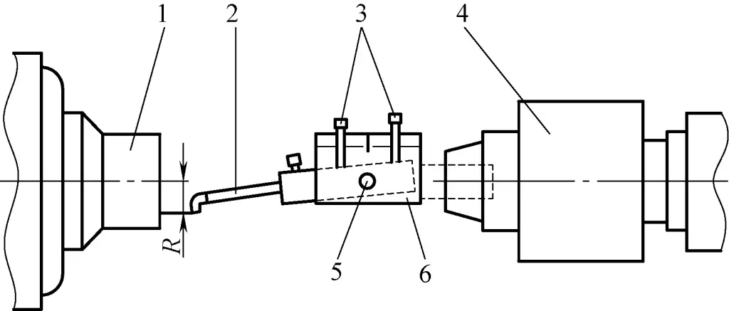
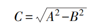
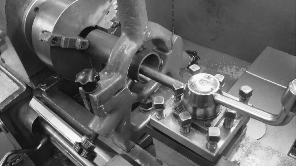
Figure 25 shows the most basic method used for boring on a lathe. When the workpiece is too large or long to be conveniently mounted on the lathe, the method of mounting the workpiece on the compound slide for boring is often used.
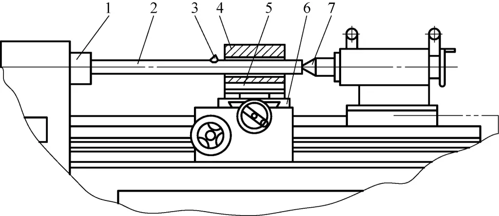
1—Spindle
2—Boring bar
3—Cutting head
4—Workpiece
5—Fixture
6—Compound slide
7—Tailstock center
Remove the small slide and tool post from the compound slide. The fixture 5 is fixed to the compound slide through T-slots. The boring bar is installed between the centers of the spindle and tailstock, allowing the boring bar to rotate while the workpiece remains stationary for machining.
To determine the boring position, machining lines can be drawn on both ends of the workpiece. A steel wire needle is fixed to the cutting head 3. Rotate the spindle and boring bar to align the needle tip with the machining line marks on both ends of the workpiece for positioning. The lateral position of the workpiece is adjusted through the compound slide, while the height is adjusted using shims or packing plates.
This boring method requires high precision center holes at both ends of the boring bar 2, and fixed centers should be used (rotating centers have larger rotation errors).
During precision boring, when the back cutting depth needs to be increased by a small amount (such as 0.05~0.1mm), it is difficult to control using the scale on the compound slide handle.
In this case, besides the previously introduced dial indicator control method and rotating the small slide angle to control radial feed, the vertical tool mounting method shown in Figure 26b can be used. This positions the boring head vertically on the workpiece (instead of horizontally as shown in Figure 26a), allowing the boring tool to cut at the top of the workpiece. When the compound slide feeds, it moves tangentially along the bore being machined.
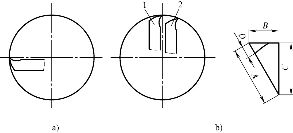
a) Normal mounting method
b) Vertical mounting method
1—Tool position before machining
2—Tool position after machining
In Figure 26b, D is the machining allowance of the hole, and C is the required tool post movement to achieve the machining allowance D. In this case:
During boring, the boring tool works in a semi-enclosed state, and the protruding part of the boring bar is relatively long, so vibration is likely to occur.
There are multiple causes of vibration, such as improper workpiece clamping, poor fixture rigidity, severe spindle bearing wear, guide rail wear, loose slide clearance adjustment, dull cutting edges, excessive boring bar protrusion (Figure 27), insufficient boring bar rigidity, incorrect cutting parameters, or improper machining methods. When vibration is detected, the cause should be identified and addressed accordingly.
To prevent and resolve vibration during boring, the following measures can be taken from a technological system perspective:
If the boring bar lacks rigidity, not only will vibration occur during boring, but also a “tool deflection” phenomenon, resulting in a tapered hole with a decreasing diameter towards the inside. If there are no issues with lathe precision, methods should be employed to increase the boring bar’s rigidity.
Methods to increase boring bar rigidity include increasing the width and thickness of the bar, but this can make it too bulky and may not fully solve the problem. Another approach is to use auxiliary supports. The following methods have some structural variations but work on the same principle.
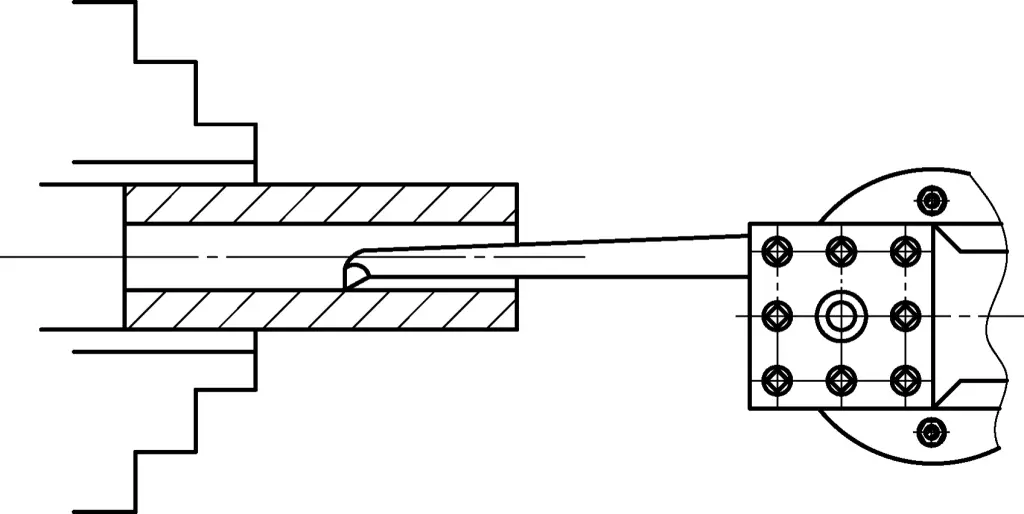
As shown in Figure 28, machine an M10 threaded hole in the boring bar and screw in a round-head bolt of appropriate length. During boring, first make a trial cut to create a 20-30mm long pre-bored hole, then stop the machine and adjust the round-head bolt on the boring bar so that the round head contacts the pre-bored hole wall. Secure the round-head bolt with a lock nut (not shown in the figure) and then proceed with boring.
1—Round-head bolt
2—Boring bar
As shown in Figure 29, install a tubular threaded connector on the back face of the boring tool tip at 180°. The tubular threaded connector has a steel ball. During boring, the steel ball can rotate freely and maintain contact with the machined surface, enhancing the rigidity of the boring bar.
1—Workpiece
2—Boring bar
3—Cutting head
4—Tubular threaded connector
5—Steel ball
For holes with large diameter and length, during boring, the method shown in Figure 30 can be used. Install one adjustment screw 180° behind the boring tool tip and another perpendicular to it. One screw head is on the same rotational surface as the boring tool tip, while the other is slightly behind it.
After adjusting the protrusion distance of the screw heads each time, tighten the lock nuts. During boring, the screw heads contact the machined surface, providing support for the boring bar.
The method of using auxiliary supports to enhance boring bar rigidity is suitable for rough boring and semi-finish boring.
When turning longer hole-type workpieces, a steady rest can be used to support the workpiece and increase its rigidity, as shown in Figure 31.
For batch processing of smaller diameter hole-type workpieces, the auxiliary support method shown in Figure 32 can be used. During boring, fix the auxiliary support on the lathe bed (like fixing a steady rest), with the groove on the support ring contacting the workpiece’s end face and outer diameter (the hole diameter of the support ring should be larger than the boring diameter). This way, when the workpiece rotates, it will also drive the support ring to rotate during the boring operation.
1—Chuck jaws
2—Workpiece
3—Support ring
4—Rolling bearing
5—Auxiliary support
Figure 33a shows a 5mm thick rubber sheet (or rubber band) wrapped around the outer circle of the workpiece, tightened with a spring, which can achieve a good vibration damping effect. Depending on the diameter and width of the thin-walled tubular workpiece, a tubular elastic band can be sewn and fitted over the outer circle of the workpiece, as shown in Figure 33b, followed by precision hole machining.
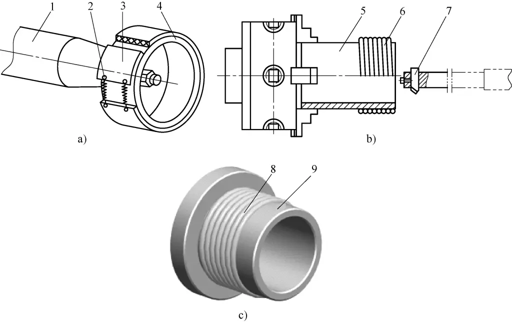
a) Using rubber sheet for vibration damping
b) Using elastic band for vibration damping
c) Using rubber tube for vibration damping
1—Mandrel
2—Spring
3—Rubber sheet
4, 5—Workpiece
6—Elastic band
7—Boring tool
8—Rubber tube
9—Tubular workpiece
Figure 33c shows wrapping a rubber tube around the outer circle of the workpiece, which can also have a certain effect. Because rubber materials are all elastomers, equivalent to a damping vibration reducer, they use damping to dissipate energy, reduce resonance amplitude, and achieve vibration elimination or reduction.
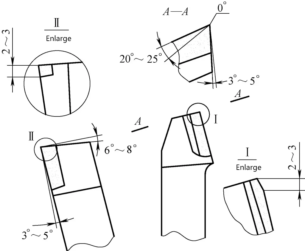
After grinding the angles of the boring tool on the grinding wheel, grind a 0° angle for 2-3mm near the tool tip’s main cutting edge, as shown in Figure 34. The purpose is that during the cutting process, due to the elastic deformation of the tool shank, a small relief angle will form at the tool tip, which is beneficial for cutting and reducing vibration.