How to Calculate Steel Weight Step-by-Step
Ever wondered how to precisely calculate the weight of steel for your construction or manufacturing project? Whether you’re an engineer,…
Imagine you’re tasked with ensuring the structural integrity of a building project, and the key to your success lies in accurately calculating the load-bearing capacity of steel beams. Whether you’re a seasoned engineer or a construction enthusiast, understanding this crucial aspect can make all the difference between a safe structure and a potential disaster. In this article, we’ll delve into the step-by-step process of calculating the load-bearing capacity of steel beams. We’ll explore the fundamental factors that impact these calculations, from material strength to beam dimensions and environmental conditions. By the end of this guide, you’ll be equipped with the knowledge to perform precise load calculations and apply structural analysis techniques confidently. Ready to ensure your beams can withstand the weight? Let’s get started!
Steel beams are essential structural elements in construction, known for their ability to support heavy loads in buildings, bridges, and various infrastructure projects. They come in various shapes and sizes, each designed to meet specific structural requirements, including I-Beams (W-Beams), H-Beams, C-Channels, T-Beams, and Angle Beams.
Steel beams play a crucial role in construction and structural engineering. Their ability to carry substantial loads, including the weight of the structure and additional forces like occupants and furniture, is crucial for ensuring structural integrity.
Steel beams offer significant flexibility in design, allowing engineers to tailor them to specific requirements. This adaptability is critical in creating innovative and efficient structures that meet both aesthetic and functional needs.
Steel beams are highly durable, resisting environmental conditions such as corrosion and temperature changes, which ensures that structures remain safe and functional for years. Their ease of installation makes them a preferred choice for many construction projects.
The performance of steel beams in a structure depends on several factors:
The strength and stiffness of the steel used in beams are critical determinants of their load-bearing capacity. Commonly used steels include ASTM A36 and A992, which offer high yield strengths and excellent weldability.
The dimensions and shape of a steel beam significantly impact its performance. Key geometric properties include the moment of inertia and section modulus, which influence the beam’s ability to resist bending and shear forces.
The manner in which a steel beam is supported in a structure affects its load-bearing capacity. Common support configurations include simply supported, fixed, and cantilevered beams, each providing different levels of stability and load distribution.
Steel beams are versatile and strong, making them suitable for high-rise buildings, bridges, industrial facilities, and residential homes. Their versatility and strength make them ideal for a wide range of applications, providing essential support and ensuring the stability and safety of various structures.
Load calculation is a crucial step in structural engineering, used to determine the forces a structure must endure. It involves estimating the various loads acting on a structural element, such as a steel beam, ensuring it can support these loads safely and efficiently.
Accurate load calculation is vital as it directly impacts the design, safety, and longevity of structures. By understanding the types and magnitudes of loads, engineers can design structures that are safe and compliant with building codes, optimize material usage to reduce costs, and predict and mitigate potential structural failures.
Dead loads are constant, unchanging forces such as the self-weight of the structure and permanent fixtures like floors and roofs.
Live loads are dynamic forces that can vary in magnitude and location. Examples include the weight of occupants, movable furniture and equipment, and vehicles in structures like bridges and parking garages.
Environmental loads, like snow, wind, and seismic forces, vary with location and climate.
Structures are often subjected to multiple types of loads simultaneously. Engineers use specific load combinations to ensure the structure can withstand these combined effects. The American Institute of Steel Construction (AISC) provides guidelines for combining loads using methods such as:
To calculate the maximum bending moment for a simply supported beam under a uniformly distributed load (UDL), use the formula:
where:
The properties of the beam’s cross-section are crucial for its ability to resist loads. Key properties include:
To ensure the beam can safely support the calculated loads, engineers verify its capacity against the demands. This involves checking:
ϕMn≥Mu(LRFD)orMn/Ω≥Ma(ASD)
Vn=0.6FyAwCv
where ( Fy ) is the yield strength of the material, ( Aw ) is the web area, and ( Cv ) is the shear coefficient.
Understanding the basics of load calculation is essential for ensuring the safety and efficiency of steel structures. By accurately identifying and combining loads, and verifying beam capacities, engineers can design robust and reliable structures.
Yield strength measures the maximum stress a material can withstand without permanent deformation. Higher yield strengths mean a material can support heavier loads. For instance, common steel grades like ASTM A36 and A992 have high yield strengths, making them ideal for structural uses.
The modulus of elasticity, or Young’s modulus, measures a material’s stiffness; a higher modulus means the steel beam will deflect less under load, thereby enhancing its load-bearing capability.
The moment of inertia is a key property that determines how well a beam resists bending. It relies on the beam’s shape and size. Beams with a higher moment of inertia can handle greater bending forces and support heavier loads.
The cross-sectional area affects a beam’s ability to handle axial loads. Larger areas allow beams to support more weight without buckling, which is crucial for columns facing significant axial loads.
The nature of the load affects the load-bearing capacity. Point loads are concentrated at specific points, while uniformly distributed loads (UDLs) spread across the beam’s length. UDLs are more common in floors and walls, whereas point loads are typical for concentrated weights like machinery.
Temporary loads, such as construction equipment, differ from permanent loads, like the weight of the structure itself. The beam’s design must account for both types to ensure safety and functionality over time.
The way a beam is supported influences its load-bearing capacity. Simply supported beams have supports at both ends, fixed beams are rigidly connected at both ends, and cantilevered beams are fixed at one end only. Each support condition affects the bending moment and shear forces experienced by the beam.
Temperature changes can affect steel’s properties. High temperatures can reduce yield strength, while low temperatures can make steel brittle. Design must consider these environmental conditions to ensure safety.
Exposure to corrosive environments, such as coastal areas, can degrade steel beams over time. Protective coatings and regular maintenance are essential to preserve the load-bearing capacity.
Load bearing capacity is the maximum load a beam can support without failure. It encompasses the beam’s ability to withstand bending, shear, and axial forces. Engineers use various calculations and design standards, such as AISC 360, to determine and verify this capacity.
Begin by collecting all necessary data to accurately calculate the load-bearing capacity of a steel beam.
Identify the type of steel used, including its yield strength ((F_y)) and modulus of elasticity ((E)). Common steels include ASTM A36 and A992, with yield strengths of 250 MPa and 345 MPa, respectively.
Identify the beam’s dimensions and cross-sectional properties, including:
Classify the loads the beam will encounter into three main types:
Permanent loads, such as the weight of the structure and fixed equipment, that do not change over time.
Variable loads that can change in magnitude and location, like occupants, furniture, and vehicles.
Loads resulting from environmental factors, including wind, snow, and seismic activity.
Apply appropriate formulas to calculate the maximum bending moment and shear forces.
For a simply supported beam under a uniformly distributed load ((w)), use:
For a point load (P) at the center:
For a uniformly distributed load:
For a point load:
Use structural analysis methods to determine internal stresses and deflections, and calculate the beam’s moment capacity using:
where (Zx) is the plastic section modulus for plastic design or (Sx) for elastic design.
Calculate shear capacity with:
where (Aw) is the web area and (Cv) is a shear coefficient.
Ensure the calculated capacities meet the design requirements.
Verify:
Check deflection limits using:
Ensure compliance with building codes, typically (L/360) for live loads.
If any criteria fail, select a larger section size or adjust material properties and recheck all calculations. Use tools like the AISC Steel Construction Manual and online calculators for efficiency. Continue iterating until all design requirements are satisfied.
Steel beam design must adhere to established guidelines to ensure safety and performance. The American Institute of Steel Construction (AISC) 360 Guidelines are paramount, providing two primary methods for design:
ASD uses service loads and safety factors to establish stress limits. This traditional method ensures that stresses remain within safe limits during normal operating conditions.
LRFD is a more modern approach, applying factored loads and resistance factors to check the strength of beams. It considers both ultimate strength and serviceability, making it a comprehensive method for modern structural engineering.
Designing steel beams involves several critical steps:
Identify the types and magnitudes of loads acting on the beam, including dead loads (permanent fixtures and the beam’s own weight) and live loads (variable forces like occupants and furniture). For ultimate limit states (ULS), factored loads such as 1.2 times dead load plus 1.6 times live load are used. Next, determine the beam’s geometric properties, including the moment of inertia (I) and section modulus (S). These properties are essential for assessing the beam’s ability to resist bending and shear forces.
Calculate the beam’s nominal flexural strength (M_n) and check against the required bending moment (M_u). For LRFD, ensure that M_u is less than or equal to φ_b M_n (where φ_b is the bending resistance factor, typically 0.9).
Verify that the beam can resist shear forces by ensuring V_u (factored shear load) is less than or equal to φ_v V_n (nominal shear strength, with φ_v typically 0.9).
Several factors influence the load-bearing capacity of steel beams:
The yield strength of the steel, such as ASTM A36 (36 ksi) or A992 (50 ksi), directly impacts the beam’s capacity. Higher yield strength means the beam can support greater loads without permanent deformation.
Consider the unbraced length of the beam and use moment gradient factors to reduce the risk of buckling.
Ensure that flange and web slenderness ratios comply with AISC limits to prevent local buckling. Properly proportioned sections are less prone to buckling under load.
Modern tools simplify the complex calculations involved in steel beam design:
SkyCiv provides online calculators that automatically incorporate AISC 360-22 guidelines for bending, shear, and axial load calculations. These tools streamline the design process by automating many checks required by the guidelines.
When using these tools, input parameters include span length, load type (point load or uniformly distributed load), support conditions, and safety factors. Accurate input ensures reliable output for design decisions.
Several practical aspects must be considered in steel beam design:
Use appropriate safety factors, such as φ_b = 0.9 for bending and φ_v = 0.9 for shear, to ensure the beam can support the required loads without failure. Ensure deflection limits meet serviceability requirements, typically L/360 for live loads and L/240 for total loads. Excessive deflection can compromise structural integrity and usability.
For floor and roof beams, consider the interaction with concrete slabs. This composite action increases the effective stiffness and load-bearing capacity.
Avoiding common pitfalls in steel beam design is crucial for ensuring safety and performance:
Accurately model tributary areas for distributed loads to avoid underestimating the loads acting on the beam.
Use interaction equations to account for combined stresses from shear and bending. This ensures the beam can safely handle complex load scenarios.
Verify the capacities of welds and bolts at connections to prevent localized failures. Proper detailing is critical for transferring loads effectively.
Staying updated with the latest standards and best practices is essential:
The latest AISC guidelines emphasize performance-based design, especially for seismic and wind loads. Adopting these standards ensures compliance with current safety requirements.
Utilize parametric design tools to expedite iterative checks for multiple load cases. Automation reduces the time and effort required for detailed design processes.
By integrating these considerations into steel beam design, engineers can ensure robust, safe, and compliant structures.
Steel beam load calculators are vital tools that help engineers determine the load-bearing capacity of steel beams in various construction projects. These calculators simplify complex calculations, ensuring that the beams used can safely support the anticipated loads. By inputting specific details about the beam and the loads it will carry, these tools provide precise results that adhere to industry standards.
Input Parameters:
Load Types:
Support Conditions:
Before using a steel beam load calculator, gather all necessary information, including beam specifications, load details, and support conditions.
Collect all necessary data:
Enter the gathered information into the calculator:
After inputting the data, the calculator will compute the load-bearing capacity of the beam. This typically includes:
Once the calculation is complete, review the outputs provided by the calculator:
Several reliable online tools are available for calculating steel beam load capacities:
By effectively using steel beam load calculators, engineers can ensure their designs are both safe and efficient, optimizing the structural integrity of their projects.
To evaluate the impact of web openings on the strength and load-bearing capacity of steel beams.
Experimental tests and finite element analysis (FEA) were conducted to assess beams with varying web post widths and different shapes of web openings. The experimental setup involved subjecting beams to controlled loads, revealing that the width of the web post significantly influences their strength. Additionally, the shape of the web openings played a crucial role in determining the structural integrity of the beams, with certain shapes causing more pronounced strength reductions.
To determine the residual load-bearing capacity of steel structural members that have been exposed to fire.
A computer program called SAFIR was utilized to simulate fire scenarios and evaluate the subsequent loading conditions until failure. The simulation included different fire intensities and durations to mimic real-world conditions.
The results showed that fire exposure can greatly reduce the load-bearing capacity of steel columns and beams. However, some elements retained a substantial amount of their original strength post-fire. The study underscored the importance of assessing residual capacity for fire-damaged structures to ensure safety and determine necessary repairs or reinforcements.
To investigate the shear and bearing capacity of steel beam bridges affected by corrosion.
Parametric studies were performed on both unstiffened and stiffened girders subjected to varying degrees of corrosion. These studies involved detailed measurements and analyses of the beams’ performance under load.
Corrosion significantly reduced the load-bearing capacity of steel beams. The extent of reduction depended on the severity of the corrosion and the type of girder. Stiffened girders showed better resistance to corrosion compared to unstiffened ones. The study highlighted the critical need for regular maintenance and protective measures to mitigate the effects of corrosion on steel structures.
To assess how temperature variations affect the load-bearing capacity of steel beams.
Steel beams were exposed to different temperature conditions, ranging from extreme cold to high heat, and their load-bearing capacities were measured. The tests included both short-term and long-term exposure to understand the material’s response.
Temperature variations had a notable impact on the load-bearing capacity of steel beams. High temperatures led to a reduction in yield strength, making the beams more susceptible to deformation under load. In contrast, low temperatures made the steel more brittle, potentially causing sudden failure under stress. These findings emphasize the importance of considering temperature effects in the design and analysis of steel structures, particularly in regions with significant temperature fluctuations.
Below are answers to some frequently asked questions:
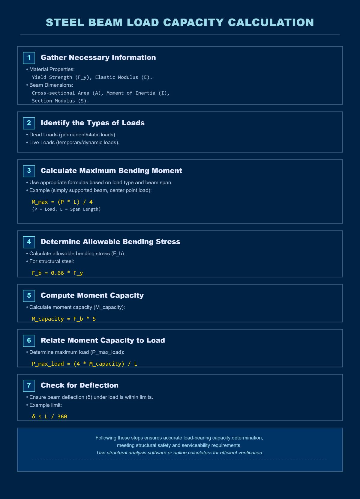
To calculate the load-bearing capacity of a steel beam, follow these steps:
Gather Necessary Information:
Identify the Types of Loads:
Calculate the Maximum Bending Moment:
Determine the Allowable Bending Stress:
Compute the Moment Capacity:
Relate Moment Capacity to Load:
Check for Deflection:
By following these steps, you can accurately determine the load-bearing capacity of a steel beam, ensuring it meets structural safety and serviceability requirements. Use structural analysis software or online calculators for efficient verification.
Several factors affect the load-bearing capacity of steel beams, primarily:
Material Properties: The grade of steel (e.g., S275, S355) determines the yield strength, tensile strength, and modulus of elasticity. Higher-grade steels, such as S355, have greater load-bearing capacity compared to lower grades like S275.
Cross-Sectional Geometry: The shape and dimensions of the beam significantly influence its capacity. I-beams are optimized for bending resistance, while hollow sections provide strength in multiple directions. Key dimensions include flange width, web thickness, and overall depth.
Load Type and Distribution: Different loads impact beams differently. Bending strength is crucial for horizontal beams, while shear capacity depends on web thickness. Compression and buckling need to be analyzed, especially for vertical columns, considering the slenderness ratio.
Environmental and External Conditions: Factors such as temperature fluctuations, corrosion, and external impacts can alter the material properties and overall performance of the steel beam.
Manufacturing and Design Factors: Quality of welding and connections can introduce stress concentrations, affecting the beam’s effective capacity. Additionally, safety factors are applied to account for material defects and uncertainties in load predictions.
Understanding these factors helps in accurately calculating the load-bearing capacity and ensuring the structural integrity of steel beams in various applications.
Yes, there are several online tools and calculators available for calculating the load-bearing capacity of steel beams. Some of the recommended tools include:
SkyCiv I Beam Load Capacity Calculator: This tool calculates bending, shear, axial, and tension capacities in compliance with AISC 360 standards. It also generates detailed design reports with clause references for validation.
Omni Calculator Beam Load Tool: This calculator helps determine reactions for simply supported beams under point loads. Users can input span length, load magnitudes, and distances.
SkyCiv Free Beam Calculator: It analyzes bending moments, shear forces, deflection, and stress for cantilever and simply supported beams. It supports various load types, including concentrated and distributed loads.
ClearCalcs Free Beam Calculator: This tool uses finite element analysis (FEA) to compute shear forces, moments, and deflections. It allows customization with named loads and mixed load types.
WebStructural Beam Designer: This platform validates forces in beams with multiple spans and complex loading conditions.
These tools provide valuable assistance in quickly and accurately determining the load-bearing capacity of steel beams, ensuring compliance with engineering standards and improving design efficiency.
Beam span significantly affects the load-bearing capacity of a steel beam through bending stress and deflection mechanics. As the span length increases, the bending moments grow exponentially, proportional to the square of the span length. This causes higher bending stress, requiring more robust beam sections to maintain structural integrity. Additionally, deflection rises with the fourth power of the span length, which can lead to excessive deformation under load, compromising the beam’s functionality.
Factors such as material properties, including steel’s modulus of elasticity and moment of inertia, play a crucial role in determining the beam’s stiffness and resistance to bending. The type of load, whether uniformly distributed or point loads, also influences the bending moments and deflection patterns. Support conditions, such as simply supported or fixed beams, impact stress distribution and overall load capacity.
Precise calculations are essential to ensure the beam can safely carry the intended loads, and shortening the span or using composite sections can enhance load-bearing capacity for longer spans. Always consult structural engineering standards and guidelines for verification and validation.
When calculating the load-bearing capacity of a steel beam, avoid common mistakes to ensure accurate results. First, correctly identify the types of loads involved, including dead loads (permanent structural weight), live loads (temporary or variable forces), and dynamic loads (such as vibrations). Using incorrect or outdated material properties for yield strength or modulus of elasticity can lead to errors; always validate material certifications and adhere to region-specific design codes like AISC or EN 1993.
Oversimplifying structural models is another frequent mistake. Simple formulas for simply supported beams might not apply to more complex scenarios such as continuous beams or cantilevers. Utilize advanced software tools like STAAD.Pro or Tekla for precise modeling. Additionally, don’t neglect shear resistance and local buckling considerations, which require attention to web slenderness and flange/web width-to-thickness ratios.
Ensure adequate bearing length calculations to avoid web crushing or support failure. Finally, accurately assess deflection limits under characteristic loads to prevent excessive deflection. By systematically addressing these issues, engineers can ensure robust and compliant steel beam designs.