Hydraulic Transmission 101: Principles and System Components
What if the key to powering heavy machinery lies in fluid motion rather than mechanical parts? Hydraulic transmission offers just…
In hydraulic systems, components such as accumulators, filters, tanks, heat exchangers, and pipes are auxiliary components. These components have relatively simple structures and singular functions, but they directly affect the working performance, noise, temperature rise, and reliability of the hydraulic system.
Therefore, sufficient attention should be paid to hydraulic auxiliary components. Among hydraulic auxiliary components, most components have been standardized and are produced by specialized manufacturers, which can be selected during the design process. Only a few non-standard components like oil tanks have fewer varieties and significantly different requirements, sometimes needing to be designed according to the requirements of hydraulic equipment.
In hydraulic systems, due to internal formation or external intrusion, contaminants are inevitably present in the hydraulic oil. These contaminant particles not only accelerate the wear of hydraulic components but also clog small holes in valves, jam valve spools, scratch seals, causing hydraulic valves to malfunction and system failures.
Therefore, it is necessary to clean the impurities and contaminant particles in the hydraulic oil. Currently, the most effective method to control the cleanliness of hydraulic oil is to use filters. The main function of filters is to filter the hydraulic oil and control its cleanliness level.
The main performance indicators of filters include filtration accuracy, flow capacity, pressure loss, etc., with filtration accuracy being the primary indicator.
1) Filtration accuracy
Filters use filter elements with specific pore sizes to filter contaminants. Filtration accuracy refers to the maximum size of impurity particles (represented by the average particle diameter d) filtered out of the hydraulic oil by the filter.
Currently used filters can be divided into four levels according to filtration accuracy: coarse filters (d≥0.1mm), standard filters (d≥0.01mm), fine filters (d≥0.001mm), and ultra-fine filters (d≥0.0001mm).
The principle for selecting filtration accuracy is to ensure that the size of filtered contaminant particles is less than half the size of the sealing clearance in hydraulic components. The higher the system pressure, the smaller the fitting clearance between relatively moving parts in hydraulic components, thus requiring higher filtration accuracy. The filtration accuracy of a hydraulic system mainly depends on the system pressure. Table 6-1 lists the recommended values for filter filtration accuracy.
Table 1 Recommended values for filter filtration accuracy
| System type | Lubrication system | Transmission system | Servo system | ||
| Pressure/MPa | 0-2.5 | 14 | 4<p<21 | >21 | 21 |
| Filtration accuracy/μm | 100 | 25-50 | 25 | 10 | 5 |
2) Flow capacity
The flow capacity of a filter is generally expressed as the rated flow, which is proportional to the filtration area of the filter element.
3) Pressure loss
The pressure difference between the inlet and outlet of the filter at rated flow. Generally, the stronger the flow capacity of the filter, the smaller the pressure loss.
4) Other performance characteristics
Other performance characteristics of filters mainly refer to qualitative indicators such as filter element strength, filter element lifespan, and filter element corrosion resistance. These characteristics can vary significantly among different filters, and their advantages and disadvantages can be determined through comparison.
According to the filtration mechanism, filters can be divided into two categories: mechanical filters and magnetic filters. The former traps particles of contaminants on one side of the filter element as the hydraulic oil passes through the pores of the filter element; the latter uses a magnetic filter element to adsorb ferromagnetic particles in the hydraulic oil as it passes through.
Mechanical filters are commonly used in general hydraulic systems, while in systems with higher requirements, both types of filters mentioned above can be used in combination. Here, we will focus on introducing mechanical filters.
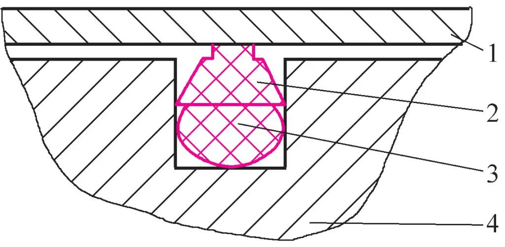
As shown in Figure 1, the wire mesh filter consists of a cylindrical plastic (or metal) skeleton with numerous holes connected between the upper end cap 1 and the lower end cap 4, with one or several layers of filter mesh 2 wrapped around the skeleton.
1—Upper end cap
2—Filter mesh
3—Skeleton
4—Lower end cap
When the filter is working, hydraulic oil enters the filter from the outside through the filter mesh and then enters the system through the upper cap port. This filter is a coarse filter with a filtration accuracy of 0.13~0.04mm and a pressure loss not exceeding 0.025MPa. The filtration accuracy of this type of filter is related to the mesh size of the copper wire mesh and the number of layers of copper mesh.
The characteristics of wire mesh filters are: simple structure, strong oil flow capacity, low pressure loss, and easy cleaning, but low filtration accuracy. They are generally installed at the suction port of hydraulic pumps to protect the pump.
1—End cap
2—Housing
3—Skeleton
4—Metal winding
The filtration accuracy has three levels: 30μm, 50μm, and 80μm, with rated flow rates of 6~250L/min. At rated flow, the pressure loss is 0.03~0.06MPa. Wire-wound filters are divided into two types: for suction pipes and for pressure pipes.
The former is installed on the suction pipe of the hydraulic pump, with a filtration accuracy of 0.05~0.1mm and a pressure loss of less than 0.02MPa at rated flow; the latter is used on the pressure pipes of hydraulic systems, with a filtration accuracy of 0.03~0.08mm and a pressure loss of less than 0.06MPa.
The characteristics of this type of filter are: simple structure, good oil flow performance, and relatively high filtration accuracy, so it is widely used. The disadvantages are that it is difficult to clean and the filter element has low strength. It is mostly used in medium and low-pressure systems.
Paper core filters use filter paper as the filtration material. The microporous filter paper, made of phenolic resin or wood pulp with a thickness of 0.35~0.7mm in plain or corrugated weave, is wrapped around a perforated tinned iron skeleton to form a paper filter core (Figure 3). The oil flows from the outside of the filter core through the filter paper into the core, then out through the passage a.
1—Filter paper
2—Skeleton
To increase the filtration area of the filter paper 1, the paper core is generally made in a folded form. This type of filter has two filtration accuracy specifications: 0.01mm and 0.02mm, with a pressure loss of 0.01~0.04MPa. Its characteristic is high filtration accuracy. The disadvantage is that it cannot be cleaned once clogged and requires regular replacement of the paper core. It has low strength and is generally used in fine filtration systems.
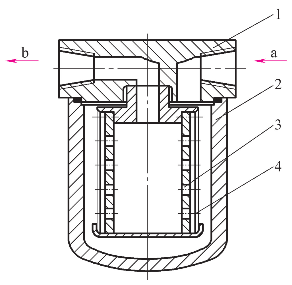
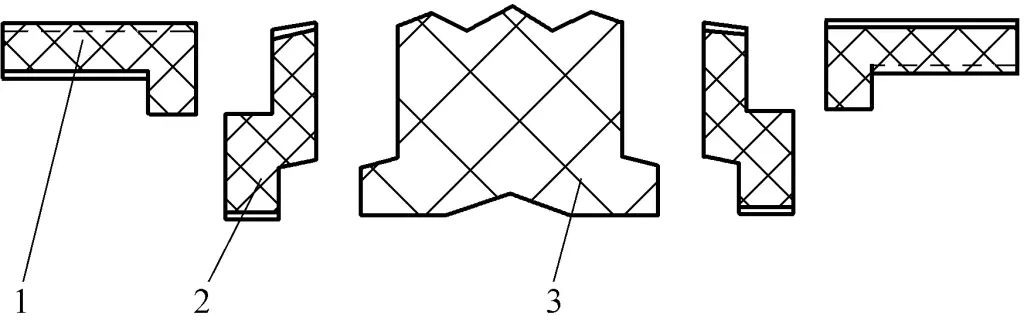
As shown in Figure 4, the sintered filter consists of an end cap 1, housing 2, and filter element 3. The filter element is made of sintered granular copper powder. The filtration process is as follows: hydraulic oil enters through hole a, passes through the micropores between the copper particles into the interior of the filter element, and flows out from hole b.
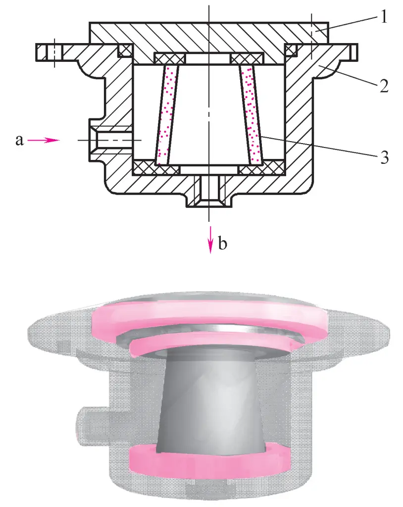
1—End cap
2—Casing
3—Filter element
The filtration accuracy of sintered filters is related to the size of micropores between copper particles on the filter element. By selecting powders with different particle sizes and making filter elements of varying thicknesses, different filtration accuracies can be achieved.
The filtration accuracy of sintered filters is 0.001-0.01mm, with a pressure loss of 0.03-0.2MPa. The characteristics of this type of filter include high strength, ability to be made into various shapes, simple manufacturing, and high filtration accuracy. The disadvantages are difficulty in cleaning and easy detachment of metal particles. It is used in situations requiring fine filtration.
When selecting a filter, the main considerations are based on the technical requirements of the hydraulic system and the characteristics of the filter. The main factors to consider are:
The system’s working pressure is one of the main bases for selecting the filter’s accuracy. The higher the system pressure, the higher the fitting accuracy of hydraulic components, and thus the higher the required filtration accuracy.
The flow capacity of the filter is determined by the maximum flow rate of the system. The rated flow of the filter should not be less than the system flow. Otherwise, the pressure loss of the filter will increase, the filter will be easily clogged, and its lifespan will be shortened. However, the larger the rated flow of the filter, the larger its volume and cost. Therefore, an appropriate flow rate should be selected.
The strength of the filter element is an important indicator. Different filter structures have different strengths. In high-pressure or high-impact hydraulic circuits, filters with high strength should be selected.
The installation of filters is determined according to the system’s needs and can generally be installed in various positions as shown in Figure 5.
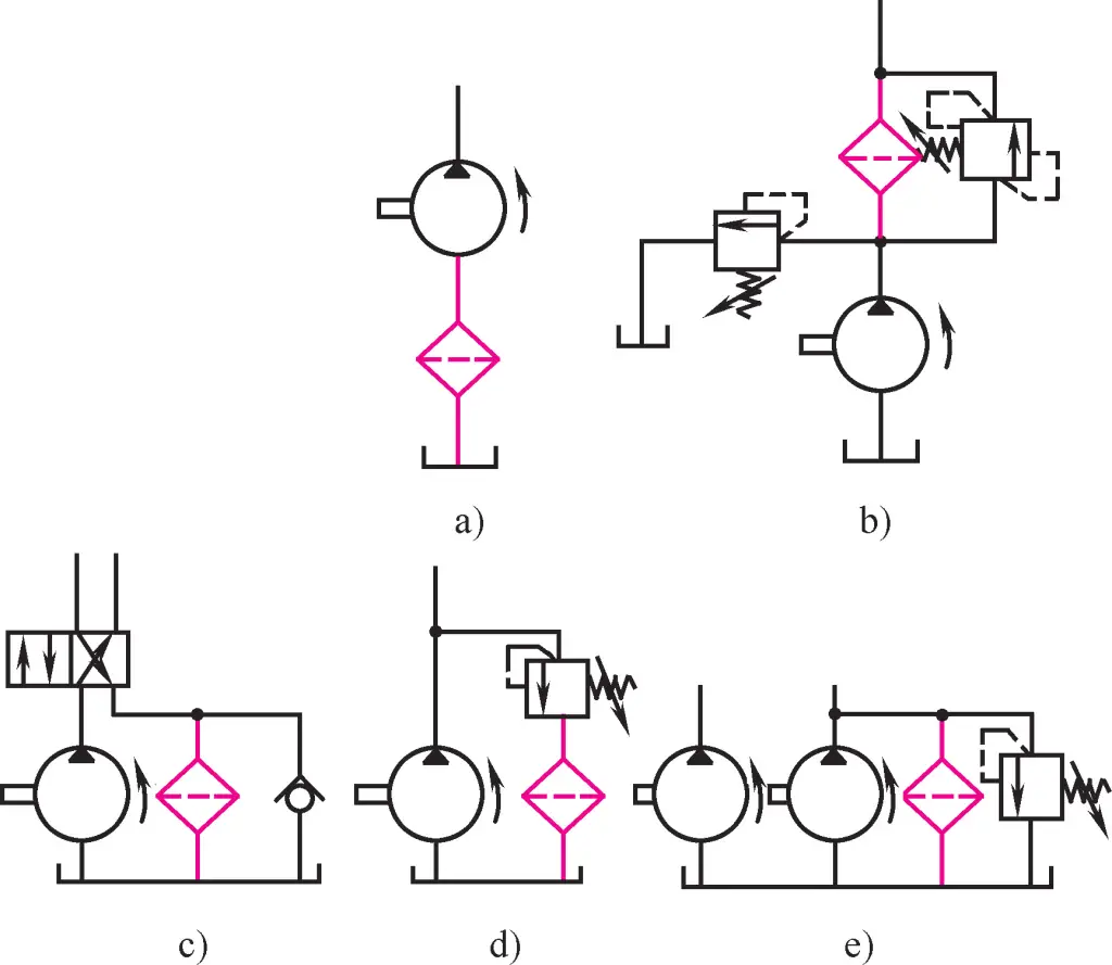
As shown in Figure 5a, installing a filter at the suction port of the hydraulic pump can protect all components in the system. However, due to the limitation of the pump’s suction resistance, only mesh filters with low pressure loss can be selected. This type of filter has low filtration accuracy, and particles generated by pump wear will enter the system, unable to fully protect other hydraulic components. Other filters need to be connected in series in the oil circuit for use.
As shown in Figure 5b, this installation method can effectively protect all hydraulic components except the pump. However, since the filter works under high pressure, the filter element needs to have higher strength. To prevent filter clogging that could cause pump overload or filter damage, a clogging indicator or bypass valve is often installed alongside the filter for protection.
As shown in Figure 5c, the filter is installed in the system’s return oil line. This method can filter out particles produced by the detachment of oxidation layers from the oil tank or pipe walls, or wear of hydraulic components, ensuring the cleanliness of hydraulic oil in the tank and protecting the hydraulic pump and other components. Since the return oil pressure is relatively low, the required filter strength does not need to be too high.
This method is shown in Figure 5d, mainly installed in the return oil line of the relief valve. This does not increase the pressure loss of the main oil line, and the filter flow can be smaller than the hydraulic pump flow, which is more economical and reasonable. However, it cannot filter all the oil and cannot ensure that impurities do not enter the system.
As shown in Figure 5e, a separate filtering circuit is formed using a hydraulic pump and filter independently from the system, which can continuously remove impurities in the system and ensure system cleanliness. It is generally used in large hydraulic systems.
An accumulator is a component in hydraulic systems that stores and releases pressure energy. It can also be used for short-term oil supply and absorption of system vibration and shock.
There are mainly three types of accumulators: weight-loaded, spring-loaded, and gas-charged.
The weight-loaded accumulator, as shown in Figure 6, uses the position change of a weight to store and release energy. The weight 1 acts on the hydraulic oil 3 through the plunger 2, generating pressure.
1—Weight
2—Plunger
3—Hydraulic oil
When storing energy, the oil enters the accumulator through hole a and a check valve, pushing the weight up through the plunger; when releasing energy, the plunger descends along with the weight, and the oil is output through hole b. This type of accumulator has a simple structure and stable pressure, but it has small capacity, large volume, inflexible response, and is prone to leakage. It is currently only used in hydraulic systems of a few large fixed equipment.
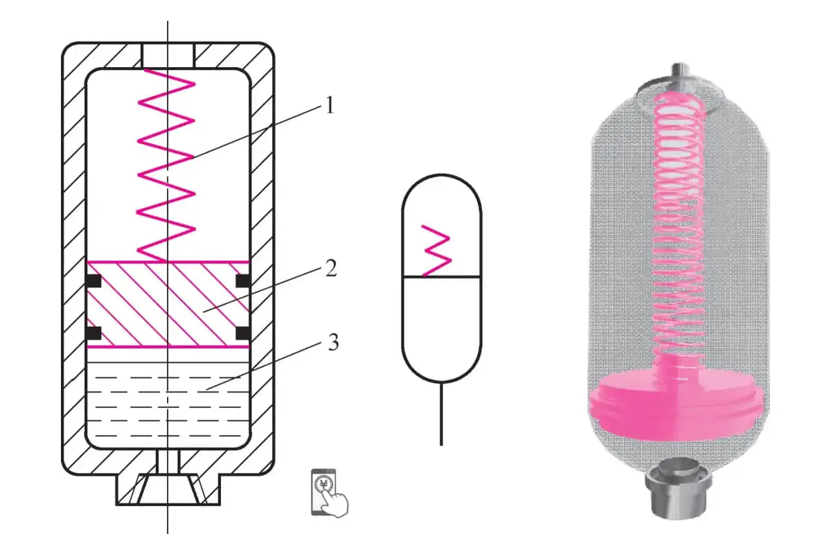
Figure 7 shows a spring-loaded accumulator, which uses the expansion and contraction of a spring to store and release energy. The force of spring 1 acts on the hydraulic oil 3 through piston 2. The pressure of the hydraulic oil depends on the preload of the spring and the effective acting area of the piston. As the spring force changes during expansion and contraction, the resulting oil pressure also changes.
To reduce this variation, generally the spring stiffness should not be too high, and the spring travel should not be too large, thus limiting the working pressure of this type of accumulator. This accumulator is used in low-pressure, small-capacity systems, often for buffering in hydraulic systems. Spring-loaded accumulators have simple structures and relatively sensitive response, but they have smaller capacity and lower pressure resistance.
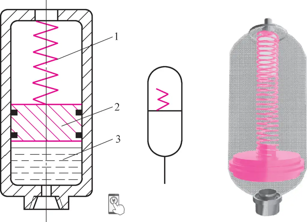
1—Spring
2—Piston
3—Hydraulic oil
Gas-charged accumulators store and release energy by compressing and expanding gas. For safety reasons, the gas used is generally an inert gas or nitrogen. The commonly used gas-charged accumulators are piston-type and bladder-type, as shown in Figure 8.
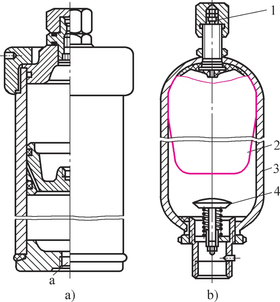
a) Piston-type accumulator
b) Bladder-type accumulator
1—Gas valve
2—Gas bladder
3—Shell
4—Limit valve
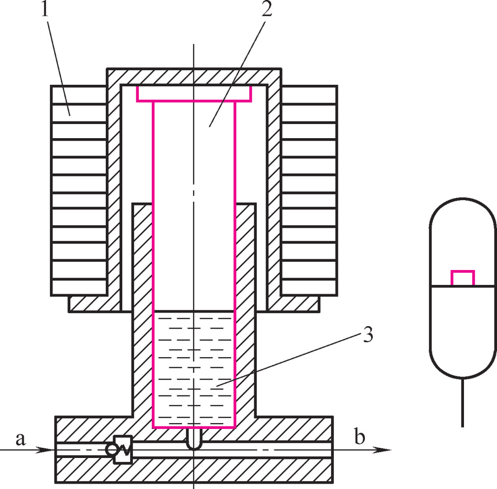
1) Piston-type accumulator Figure 8a shows a piston-type accumulator, where hydraulic oil enters through port a, pushing the piston and compressing the gas in the upper chamber to store energy. When the system pressure is lower than the pressure in the accumulator, the gas pushes the piston, releasing hydraulic oil to meet system needs.
This type of accumulator has the advantages of simple structure, reliable operation, and easy maintenance. However, due to the high machining precision of the cylinder, piston seal wear, and the influence of piston inertia and friction, it has disadvantages such as high cost, tendency to leak, and poor response sensitivity.
2) Bladder-type accumulator Figure 8b shows a bladder-type accumulator, where the gas bladder 2 is installed in the shell 3. The gas valve 1 is used to fill the bladder with nitrogen. Hydraulic oil enters the accumulator through the inlet, opening the limit valve 4 and compressing the bladder. The gas inside the bladder is compressed to store energy. When the system pressure is lower than the accumulator pressure, the bladder expands, outputting hydraulic oil, and the accumulator releases energy.
The purpose of the limit valve is to prevent the bladder from protruding and being damaged at the oil port when it expands. This type of accumulator features complete separation of gas and oil, low bladder inertia, flexible response, small structure size, light weight, and easy installation. The bladder-type accumulator is one of the most widely used accumulators today.
The capacity of an accumulator is one of the main indicators for selecting an accumulator. Different accumulators have different capacity calculation methods. Here, we will briefly introduce the capacity calculation method for the widely used bladder-type accumulator when used as an auxiliary energy source.
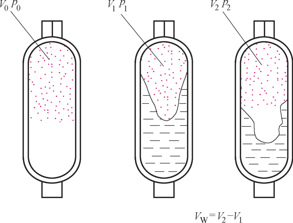
Before operation, the bladder-type accumulator needs to be pre-charged with gas. After charging, the bladder will occupy the entire volume of the accumulator shell. Assume that the volume of the bladder at this time is V0 , and the pressure is p0 . During operation, hydraulic oil enters the accumulator, compressing the bladder. At this time, the volume of gas in the bladder is V1 , and the hydraulic pressure is p1 . After the hydraulic oil is released, the bladder expands, its volume becomes V2 , and the pressure drops to p2 , as shown in Figure 9.
According to Boyle’s gas law
P0V0n=p1V1n=p2V2n=const
Where P0 and V0 are the pressure and volume of the pre-charged gas in the bladder when there is no hydraulic oil input to the accumulator; p1 and V1 are the pressure and volume of the bladder’s interior after compression during the accumulator’s working state; P2 and V2 are the pressure and volume inside the bladder after the accumulator releases energy.
n is an exponent determined by the accumulator’s working state: When the accumulator releases energy slowly, such as for pressure maintenance or leak compensation, the gas can be considered to work under isothermal conditions, taking n=1. When the accumulator rapidly releases energy, such as for large oil supply, it can be considered to work under adiabatic conditions, taking n=1.4.
Let the maximum volume of oil stored in the accumulator be V W , then
VW = V2 -V1
Combining the above two formulas, we get
V0=VW (p2/p0)1/n/[1-(p2/p1)1/n]
or
VW=V0p01/n[(1/p2)1/n-(1/p1)1/n]
Theoretically, the charging pressure p0 should be equal to the pressure p2 after energy release. However, due to system leakage, to ensure that the accumulator can still supply oil to the system when the system pressure is p2 , p0 should be < p2 . For folded bladders, p 0 = (0.8~0.85)p2 ; for corrugated bladders, take p0 = (0.6~0.65)p2 .
p 1 and p2 are the system’s maximum working pressure and the minimum working pressure to maintain system operation, respectively, both determined by system requirements. V0 is the maximum volume of the bladder, which can also be considered as the accumulator’s volume. When determining V0 , first calculate V0 using the above formula, then consult the manual to select the standard accumulator volume.
The installation position of an accumulator in a hydraulic system is determined by its function. The following points should be noted when using and installing accumulators:
The main function of the oil tank is to store oil, while the tank body also serves purposes such as heat dissipation, sediment settling, air separation from the oil, and as an installation platform.
Oil tanks can be classified into open structure and closed structure. Open structure tanks have a free oil surface that communicates with the atmosphere, mainly used in various fixed equipment; closed structure tanks have oil isolated from the atmosphere, mainly used in mobile equipment and vehicles.
Open structure oil tanks are further divided into integral and separate types. Integral oil tanks use the main machine’s base as the oil tank. They are compact and easily collect hydraulic component leakage, but have poor heat dissipation and are difficult to maintain, affecting the precision and performance of the main machine.
Separate oil tanks form an independent oil supply station, separated from the main machine. They have better heat dissipation, maintenance, and repairability than integral oil tanks, but require additional floor space. Currently, precision equipment mostly uses separate oil tanks.
Figure 10 shows an open structure separate oil tank. The tank body is generally welded from 2.5-4mm thick steel plates, with an oil-resistant coating on the surface. There are two baffles 7 and 9 in the middle of the tank to separate the hydraulic pump’s suction pipe 1 from the return pipe 4, blocking sediment and foam produced by the return pipe. The mounting plate 5 on top of the tank is made of thicker steel plate for installing the electric motor, hydraulic pump, integrated block, and other components.
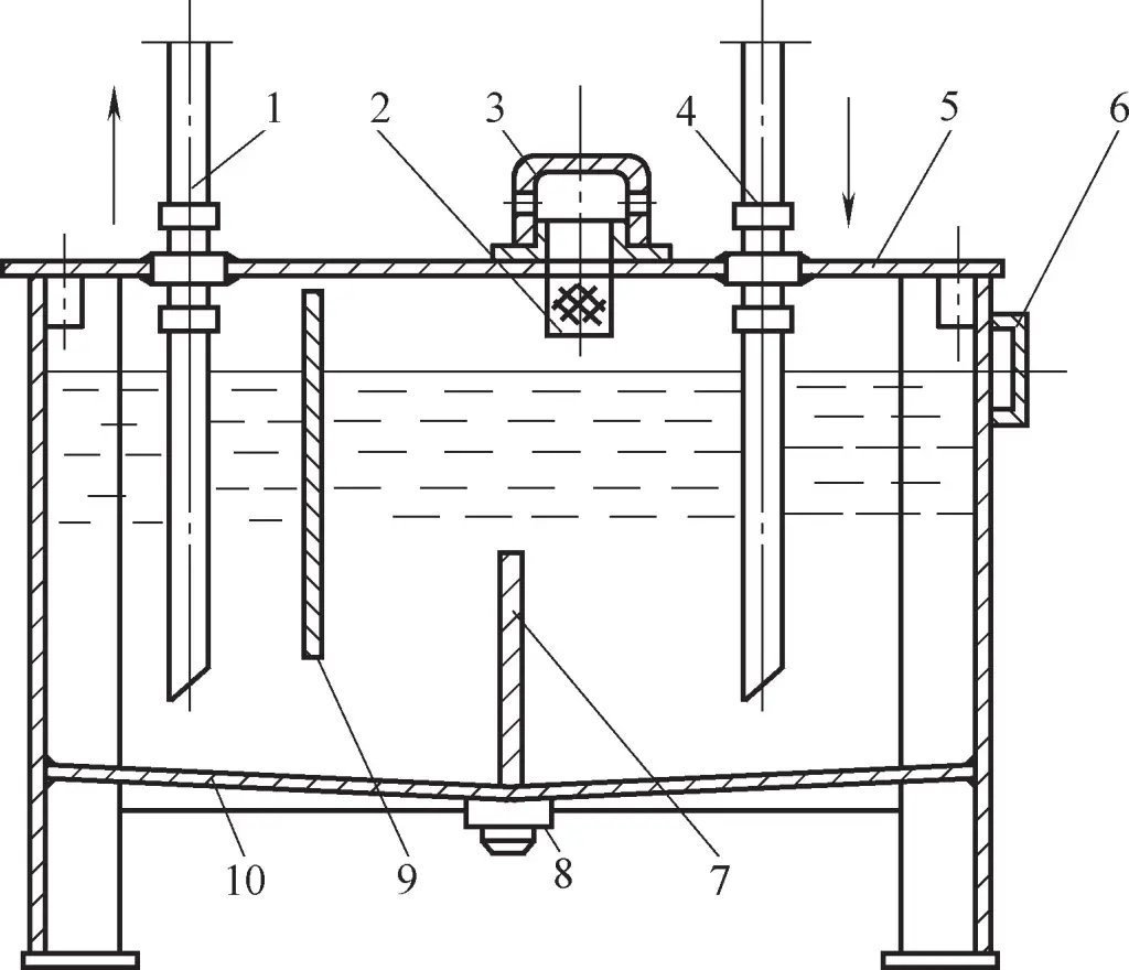
1—Suction pipe
2—Filter screen
3—Dust cover
4—Return pipe
5—Mounting plate
6—Level gauge
7—Lower baffle
8—Drain valve
9—Upper baffle
10—Tank body
The mounting plate is equipped with a filter screen 2 and dust cover 3 for filtering during oil filling and preventing foreign objects from falling into the tank. The dust cover has small holes on the side to communicate with the atmosphere. A level gauge 6 is installed on the side of the tank to display oil quantity. A drain valve 8 is installed at the bottom of the tank for draining oil and sediment during oil changes.
Oil tanks are non-standard components, often designed according to specific needs in practical situations. When designing oil tanks, the main considerations are tank volume, structure, and heat dissipation. Due to space limitations, only a brief introduction to the design approach is provided below.
The volume of the oil tank is a main parameter to be determined when designing. A larger tank volume provides better heat dissipation but uses more oil and costs more. A smaller tank volume occupies less space and reduces cost, but has insufficient heat dissipation conditions.
In practical design, an empirical formula can be used to initially determine the tank volume, then verify the tank’s heat dissipation Q₀, calculate the system’s heat generation Q₁. When the tank’s heat dissipation is greater than the hydraulic system’s heat generation (Q₂ > Q₃), the tank volume is suitable; otherwise, the tank volume needs to be increased or cooling measures adopted (refer to relevant manuals for calculating tank heat dissipation and hydraulic system heat generation).
The empirical formula for estimating oil tank volume is
V=αq
In the formula
After determining the volume, the structural design of the oil tank becomes the main task to realize various functions of the oil tank. The following points should be noted when designing the oil tank structure:
1) The tank body should have sufficient strength and rigidity. Oil tanks are generally welded from 2.5~4mm thick steel plates, and larger ones require welded reinforcing ribs.
2) A 100-200 mesh screen filter should be installed on the pump’s suction pipe, with a distance of not less than 20mm between the filter and the tank bottom. The filter should not be exposed above the oil surface to prevent the pump from sucking in air and causing noise. The system’s return oil pipe should be inserted below the oil surface to prevent splashing and bubble formation.
3) The suction pipe and return pipe should be separated, with the distance between them as far as possible. Several baffles should be used to separate them, increasing the circulation distance of the oil, allowing contaminants and bubbles in the oil to fully settle or separate. The height of the baffles is generally 3/4 of the oil surface height.
4) Anti-pollution sealing. To prevent oil contamination, sealing gaskets should be added to all connections of the cover plate and windows, and sealing rings should be added to all holes where oil pipes pass through.
5) The bottom of the oil tank should have a slope, and there should be a certain distance between the tank bottom and the ground. An oil drain plug should be installed at the lowest point of the tank bottom.
6) The inner surface of the oil tank should be specially treated. To prevent the coating on the inner wall of the oil tank from peeling off, the inner wall of new oil tanks should be shot blasted, acid washed, and surface cleaned, then coated with a layer of plastic film or oil-resistant varnish compatible with the working fluid.
When the hydraulic system is working, the temperature of the hydraulic oil should be maintained between 15-65°C. If the oil temperature is too high, the oil will deteriorate rapidly, and its viscosity will decrease, reducing the system’s efficiency. If the oil temperature is too low, the oil’s fluidity will worsen, increasing system pressure loss and reducing the pump’s self-priming ability. Therefore, maintaining the proper oil temperature is a necessary condition for the normal operation of the hydraulic system.
Due to limitations such as vehicle load, sometimes the natural regulation of the oil tank itself cannot meet the oil temperature requirements, and external facilities are needed to meet the equipment’s oil temperature requirements. Heat exchangers are the most commonly used temperature control facilities. Heat exchangers are divided into two categories: coolers and heaters.
Coolers can be classified into water-cooled, air-cooled, ammonia-cooled, and other forms based on the cooling method. Among these, water-cooled and air-cooled are the most common cooling methods.
Figure 11a shows a commonly used serpentine tube water cooler, where the serpentine tube is installed inside the oil tank, and cooling water flows through the tube to remove heat generated in the oil. This type of cooler has a simple structure and low cost, but its heat exchange efficiency is low and water consumption is high.
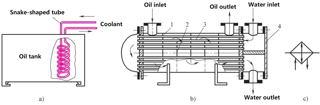
a) Serpentine tube type
b) Shell and tube type
c) Graphic symbol
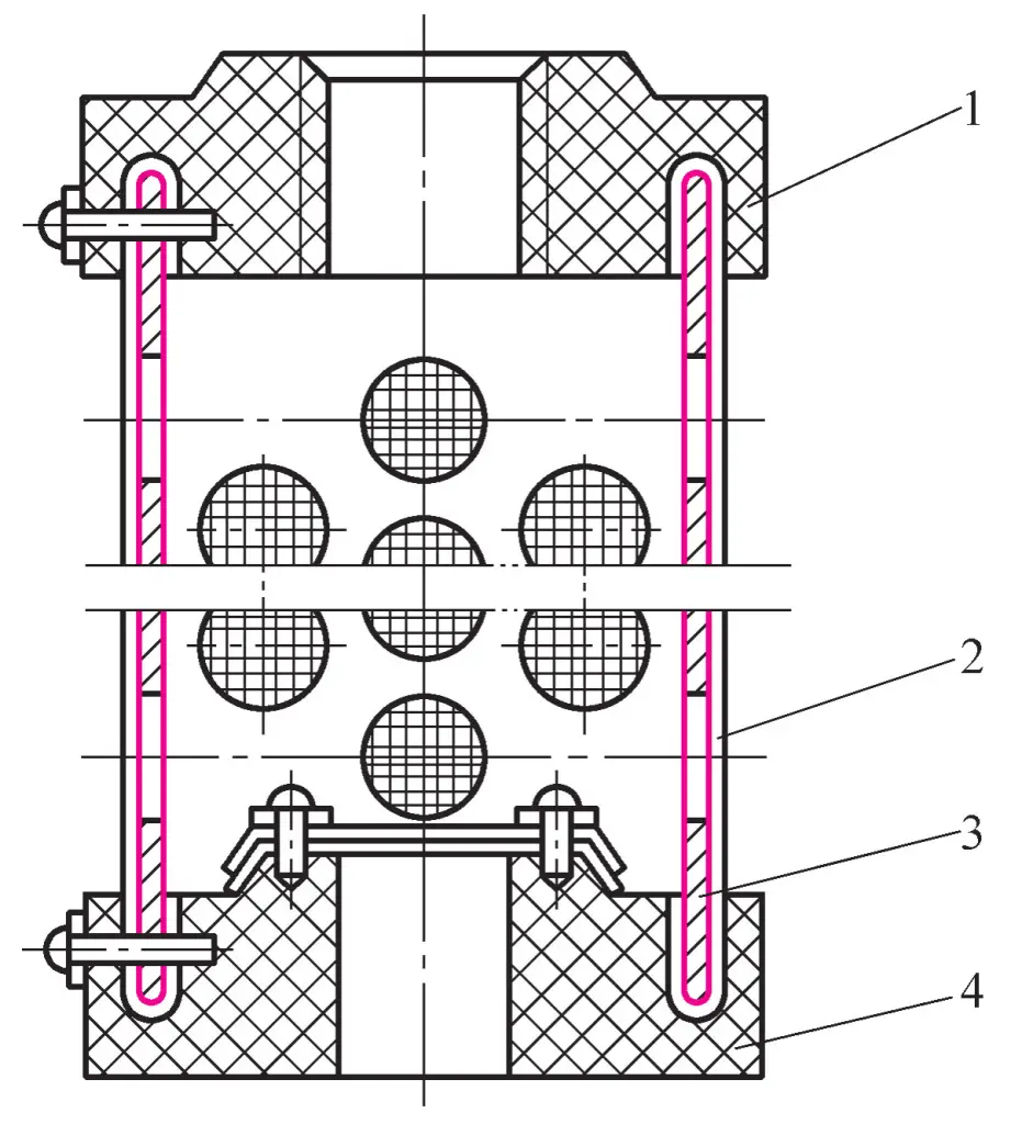
1—Shell
2—Baffle
3—Cooling copper tube
4—Right compartment of the shell
Figure 11b shows a shell and tube cooler commonly used in large equipment, consisting of a shell 1, cooling copper tubes 3, and baffles 2. Hydraulic oil enters from the left oil port of the shell 1, passes through multiple cooling copper tubes 3 and baffles for cooling, and flows out from the right port of the shell.
Cooling water enters through the upper inlet of the right compartment 4 of the shell, then flows through the upper cooling copper tubes 3 to the left end cap of the shell, and then through the lower cooling copper tubes 3, exiting from the lower outlet of the right compartment 4 of the shell. Due to the effect of multiple cooling copper tubes and baffles, this type of cooler has high heat exchange efficiency, but it is large in size and expensive.
Figure 11c shows the graphic symbol for coolers. Air-cooled radiators are more commonly used in hydraulic equipment on mobile vehicles. Air-cooled coolers can be tube-type or fin-type (single-layer tube wall), which are smaller in size but have lower cooling efficiency compared to water-cooled types.
Coolers are generally installed in the return oil line of the hydraulic system or in the overflow line of the relief valve. As shown in Figure 12, the hydraulic oil output from the pump directly enters the system, while the heated return oil and the oil overflowing from the relief valve are cooled together by the cooler 1 before returning to the oil tank. The check valve 2 is used to protect the cooler, and the shut-off valve 3 is opened when the cooler is not needed to provide a passage for the fluid flow.
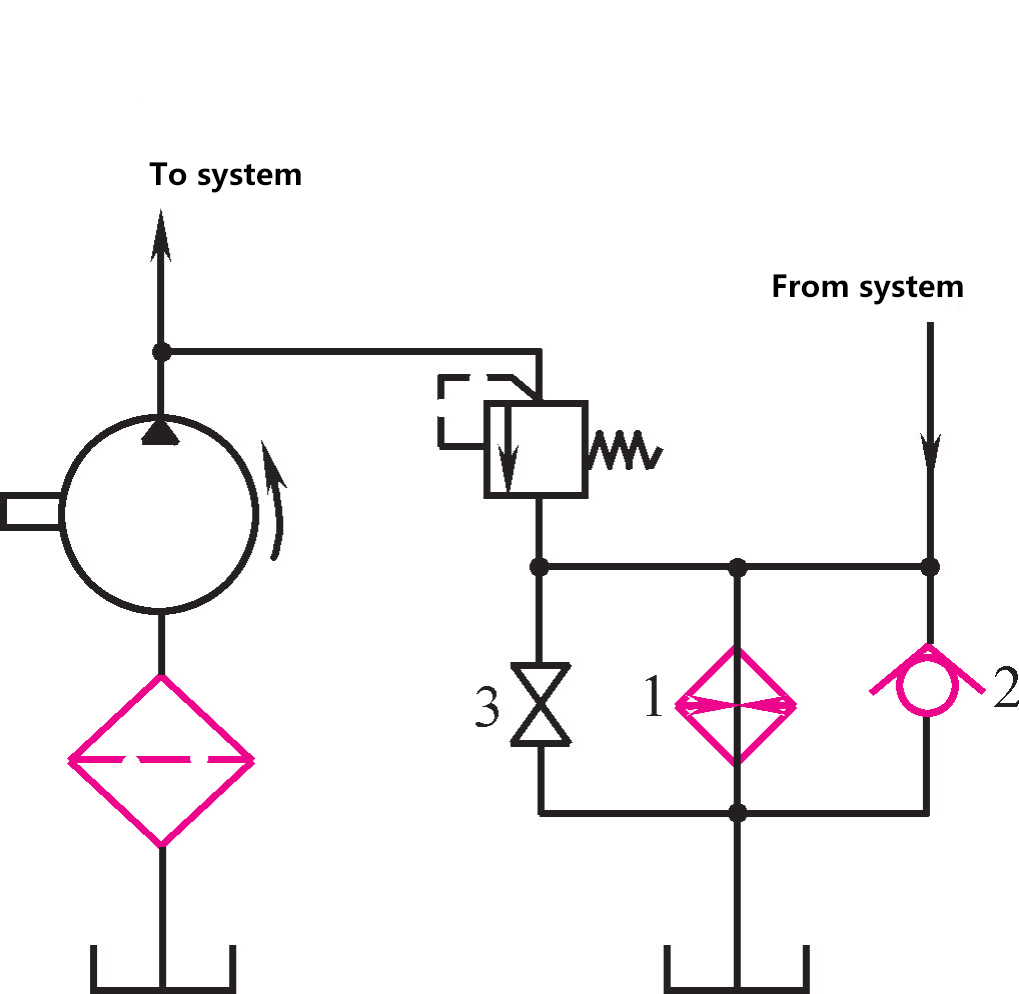
1—Cooler
2—Check valve
3—Shut-off valve
The heaters used in hydraulic systems generally adopt electric heating methods. Electric heaters have a simple structure, convenient control, can set the desired temperature, and have small temperature control errors.
However, the heating tube of the electric heater is in direct contact with the hydraulic oil, which can easily cause uneven oil temperature in the tank and sometimes accelerate oil cracking. Therefore, multiple heaters can be installed, and the heater control should not be set too high. As shown in Figure 13a, the heater 2 is installed on the tank wall of the oil tank and connected with a flange. Figure 13b shows the graphic symbol of the heater.
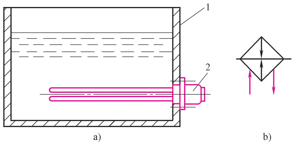
1—Oil tank
2—Heater
Oil pipes and pipe fittings are called connectors, which function to connect dispersed hydraulic components to form a complete hydraulic system. The performance and structure of connectors directly affect the working state of the hydraulic system. Here, we introduce the structures of commonly used hydraulic connectors for reference when designing hydraulic devices and selecting connectors.
In hydraulic systems, there are many types of oil pipes used, including steel pipes, copper pipes, nylon pipes, plastic pipes, rubber hoses, etc. When selecting, factors such as the high and low pressure of the hydraulic system, the installation position of hydraulic components, and the working environment of the hydraulic equipment should be considered.
1) Steel pipes
They are divided into seamless steel pipes and welded steel pipes. The former is generally used in high-pressure systems, while the latter is used in medium and low-pressure systems. The characteristics of steel pipes are: strong pressure-bearing capacity, low price, high strength, good rigidity, but difficult to assemble and bend. Currently, steel pipes are the most widely used in various hydraulic equipment.
2) Copper pipes
Copper pipes are divided into brass pipes and pure copper pipes, with pure copper pipes being more commonly used. Copper pipes have advantages such as easy assembly and bending, but also have disadvantages such as low strength, poor vibration resistance, high material price, and easy oxidation of hydraulic oil. They are generally used in difficult-to-assemble places within hydraulic devices or in medium and low-pressure systems with pressures between 0.5~10MPa.
3) Nylon pipes
This is a new type of milky white translucent pipe material, with pressure-bearing capacities of 2.5MPa and 8MPa. Nylon pipes have characteristics such as low price and convenient bending, but have a shorter lifespan. They are often used in low-pressure systems to replace copper pipes.
4) Plastic pipes
Plastic pipes are low in price and easy to install, but have poor pressure-bearing capacity and are prone to aging. Currently, they are only used for leak pipes and return oil lines.
5) Rubber hoses
These oil pipes come in high-pressure and low-pressure types. High-pressure hoses are made of oil-resistant rubber with steel wire braided layers; the more steel wire layers, the higher the pressure resistance of the oil pipe. Low-pressure hoses have braided layers of canvas or cotton thread. Rubber hoses are used for connecting hydraulic components with relative motion.
The calculation of oil pipes mainly involves determining the inner diameter and wall thickness of the pipe.
The calculation formula for the inner diameter of oil pipes is
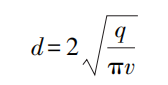
Where
The calculation formula for pipe wall thickness is
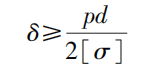
Where
For steel pipes
Pipe fittings are detachable connectors that connect pipes with hydraulic components or valve plates. Pipe fittings should meet requirements such as easy assembly and disassembly, good sealing, firm connection, small overall dimensions, low pressure drop, and good manufacturability.
There are many types of commonly used pipe fittings. By passage, there are straight-through, angled, tee, and cross types; by connection method to valve body or valve plate, there are threaded and flanged types; by connection method between pipe and fitting, there are flared, welded, ferrule, crimped, and quick-connect types. Only the latter classification will be introduced below.
Figure 14a shows a flared pipe fitting, which uses the clamping action of the sleeve for sealing. This type of pipe fitting has a simple structure and is suitable for connecting copper pipes, thin-walled steel pipes, nylon pipes, and plastic pipes.
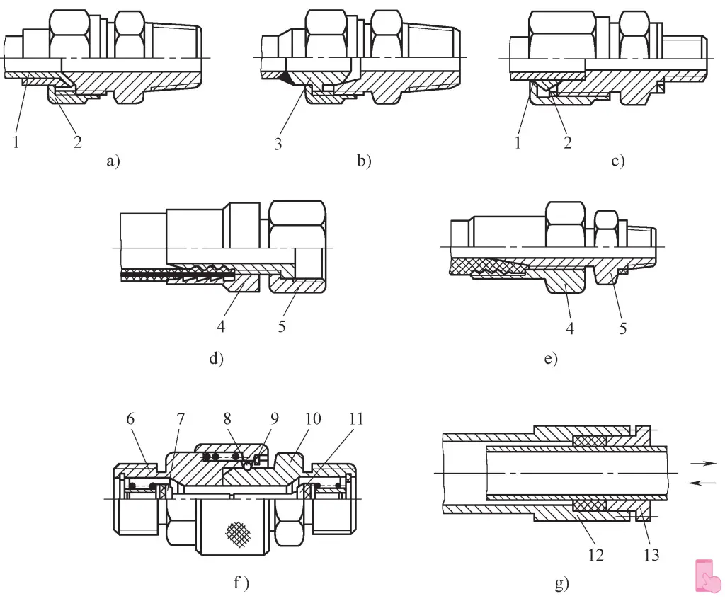
a) Flared pipe fitting
b) Welded pipe fitting
c) Ferrule pipe fitting
d) Crimped pipe fitting
e) Detachable pipe fitting
f) Quick-connect fitting
g) Telescopic pipe fitting
1—Pipe
2—Ferrule
3—Fitting inner core
4—Fitting outer sleeve
5—Fitting core
6—Socket
7, 11—Pipe plug
8—Steel ball
9—Clamp
10—Nozzle
12—Outer tube
13—Inner tube
Figure 14b shows a welded pipe fitting, where the oil pipe is welded to the inner core 3 of the fitting. The spherical surface of the inner core is tightly connected to the conical hole of the fitting body, providing good sealing, simple structure, and high pressure resistance. The disadvantage is that welding is relatively troublesome. It is suitable for connecting high-pressure thick-walled steel pipes.
Figure 14c shows a ferrule-type pipe fitting, which uses a highly elastic ferrule 2 to clamp the oil pipe 1 for sealing. Its features include simple structure and easy installation, but it requires high dimensional accuracy of the outer wall of the oil pipe. Ferrule-type pipe fittings are suitable for connecting high-pressure cold-drawn seamless steel pipes.
Figure 14d shows a crimped pipe fitting, which consists of an outer sleeve 4 and an inner core 5. This fitting is suitable for flexible hose connections.
Figure 14e shows a detachable pipe fitting. The outer sleeve 4 and inner core 5 of this fitting are hexagonal, making it convenient for frequent disassembly of flexible hoses. It is suitable for connecting high-pressure small-diameter flexible hoses.
Figure 14f shows a quick-connect coupling, which facilitates rapid assembly and disassembly of oil pipes.
The principle is as follows: When the collar 9 moves to the left, the steel balls 8 retract outward from the groove of the insert 10, releasing the insert, which can then be quickly pulled out of the socket 6. At this time, the pipe plugs 7 and 11 close the two pipe openings under their respective spring forces, preventing oil leakage from the pipes. This type of pipe fitting is suitable for flexible hose connections that require frequent disassembly.
Figure 14g shows a telescopic pipe fitting, which consists of an inner tube 13 and an outer tube 12. The inner tube can slide freely inside the outer tube and is sealed with O-rings. The outer diameter of the inner tube must be precisely machined. This type of pipe fitting is suitable for connecting pipes with relative motion between connecting parts.
Sealing is one of the effective means to solve leakage problems in hydraulic systems. When the sealing of a hydraulic system is poor, it can cause external leakage, polluting the environment; it can also allow air to enter the hydraulic system, affecting the performance of hydraulic pumps and the smooth operation of hydraulic actuators. When internal leakage is severe, it can lead to excessively low volumetric efficiency and high oil temperature rise, causing the system to malfunction.
Seals can be divided into non-contact seals and contact seals based on their working principles. The former mainly refers to clearance seals, while the latter refers to sealing element seals.
Clearance seals achieve sealing through small gaps between the mating surfaces of relatively moving parts. Clearance seals are commonly used in cylindrical mating pairs of plungers, pistons, or valves.
Hydraulic valves using clearance seals have several equally spaced pressure-balancing grooves on the outer surface of the valve spool. Their main function is to distribute radial pressure evenly, reduce hydraulic locking force, and improve the centering of the valve spool in the bore, thereby reducing leakage by minimizing the clearance.
Additionally, the resistance formed by the pressure-balancing grooves also plays a role in reducing leakage. The pressure-balancing grooves are typically 0.3-0.5mm wide and 0.5-1.0mm deep. The fitting clearance between cylindrical surfaces is related to the diameter size. For valve spools and valve bores, it is generally 0.005-0.017mm.
The advantage of this type of seal is low friction, while the disadvantage is that it cannot automatically compensate for wear. It is mainly used between cylindrical surfaces with smaller diameters, such as between plungers and cylinders in hydraulic pumps, and between valve spools and valve bores in slide valves.
O-ring seals are generally made of oil-resistant rubber with a circular cross-section. They have excellent sealing performance, with both inner and outer sides as well as end faces providing sealing action. They have compact structures, low friction for moving parts, easy manufacturing and assembly, low cost, and can be used for both high and low pressures. These characteristics have led to their widespread use in hydraulic systems.
The structure and working conditions of O-ring seals are shown in Figure 15. Figure 15a shows the external cross-section of an O-ring seal; Figure 15b shows the situation when installed in a sealing groove, where δ 1 and δ 2 are the pre-compression amounts after O-ring installation, usually expressed as compression rate W, namely
W=[(d0-h)/d0]×100%
For fixed seals, reciprocating motion seals, and rotary motion seals, the compression rates should reach 15%-20%, 10%-20%, and 5%-10% respectively to achieve satisfactory sealing effects.
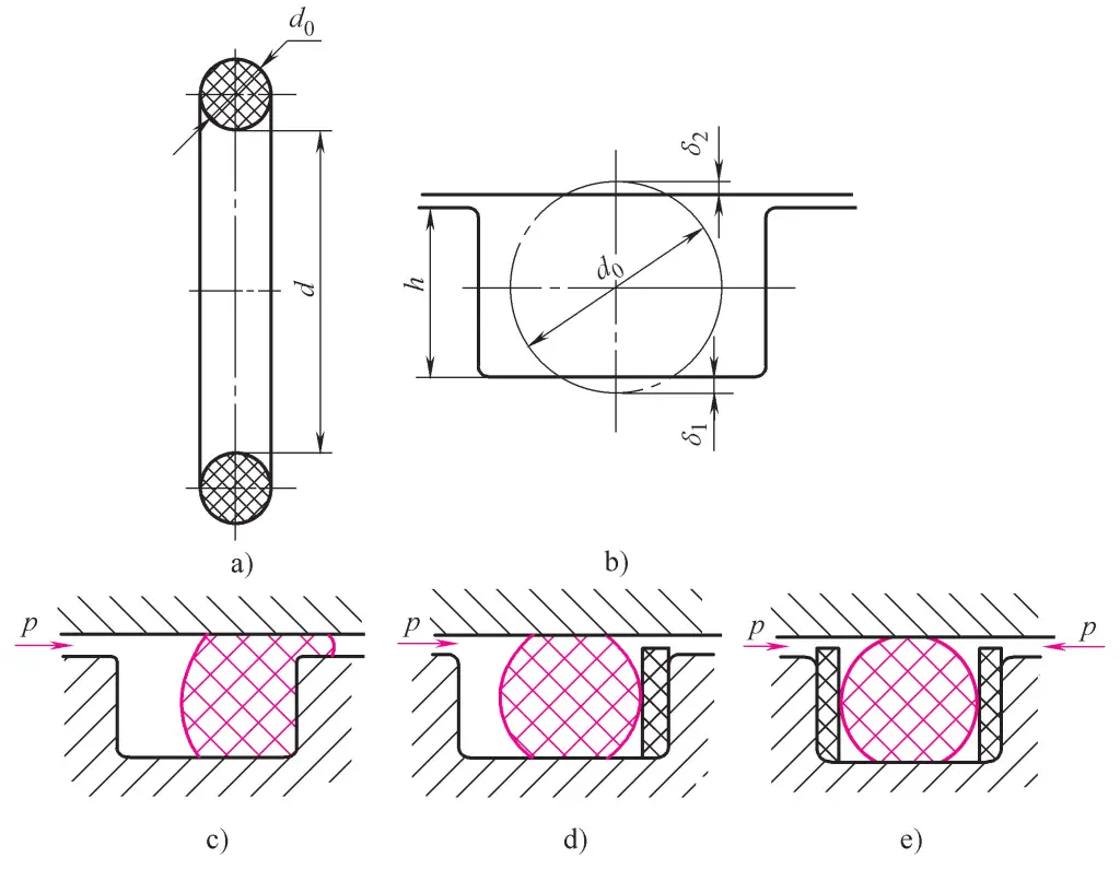
a) External cross-section
b) Situation when installed in sealing groove
c)~e) Installation methods
When the hydraulic oil working pressure exceeds 10MPa, O-ring seals can easily be damaged by being squeezed into the gap during reciprocating motion (Figure 15c). To prevent this, 1.2-1.5mm thick PTFE backup rings should be installed on its sides. For unidirectional force, one backup ring is installed on the opposite side of the force; for bidirectional force, backup rings are installed on both sides (Figures 15d, e).
The installation grooves for O-ring seals, besides rectangular, can also be V-shaped, dovetail-shaped, semicircular, triangular, etc. In practical applications, relevant manuals and national standards should be consulted.
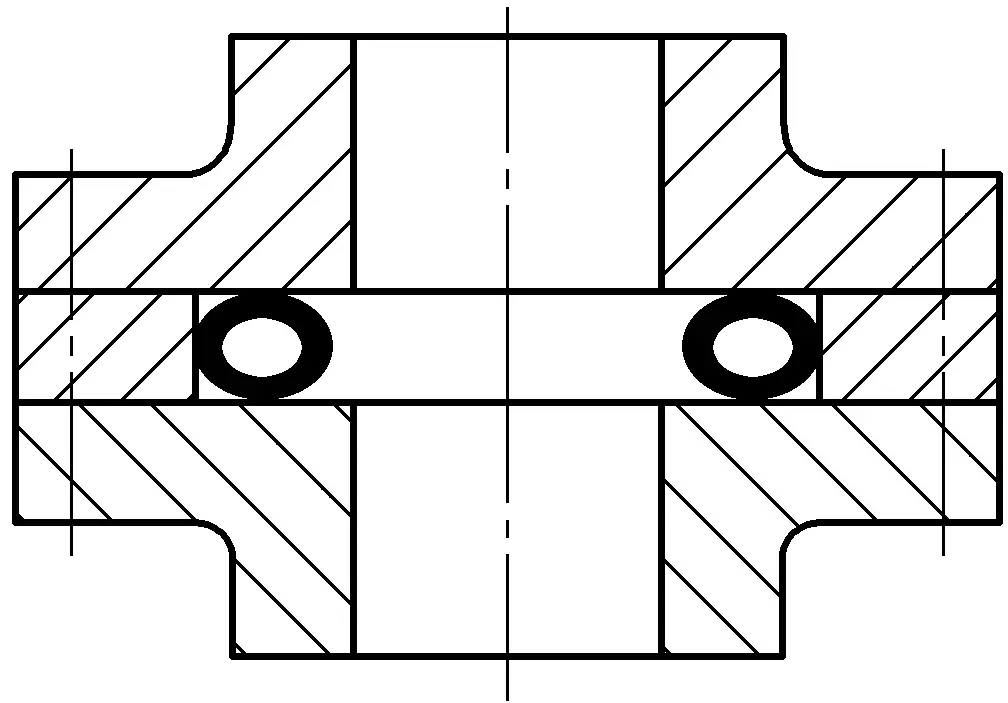
Lip seals can be classified as Y-shaped, V-shaped, U-shaped, L-shaped, etc., based on their cross-sectional shape. Their working principle is shown in Figure 16. Hydraulic pressure pushes the two lip edges of the seal against the surfaces of the two parts forming the gap.
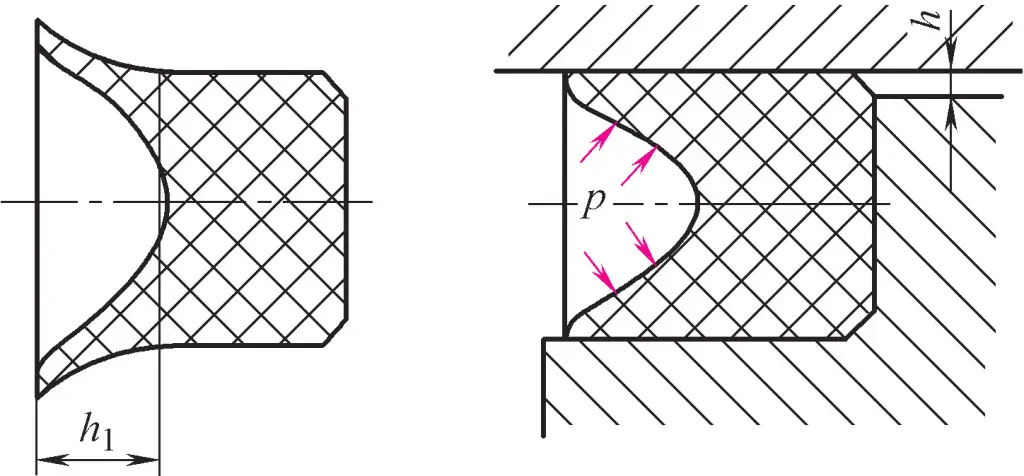
The characteristic of this sealing action is that it can automatically adjust the sealing performance according to changes in working pressure. The higher the pressure, the tighter the lip edges are pressed, resulting in better sealing; when the pressure decreases, the tightness of the lip edges also decreases, thus reducing friction resistance and power consumption. Furthermore, it can automatically compensate for wear on the lip edges.
Currently, small Y-shaped seals are widely used in hydraulic cylinders, mainly for sealing pistons and piston rods. Figure 17a shows a shaft seal, and Figure 17b shows a bore seal. The characteristic of these small Y-shaped seals is that the ratio of cross-sectional width to height is large, increasing the bottom support width, which can prevent the seal from flipping or twisting due to frictional forces.
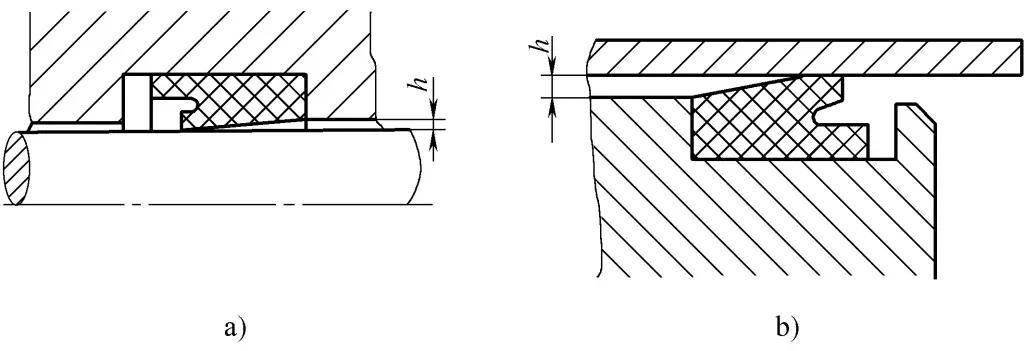
a) For shafts
b) For bores
V-shaped seals are often used for shaft sealing in high-pressure and ultra-high-pressure situations (pressures greater than 25MPa). V-shaped seals are made by pressing multiple layers of coated fabric, and their shape is shown in Figure 18.

V-shaped seals typically consist of a pressure ring, sealing ring, and support ring stacked together, which can ensure good sealing performance. When the pressure is even higher, the number of intermediate sealing rings can be increased. These seals require pre-tightening during installation, resulting in higher frictional resistance.
When installing lip seals, the lip opening should face the hydraulic oil, allowing the two lips to open and press against the surfaces of the components.
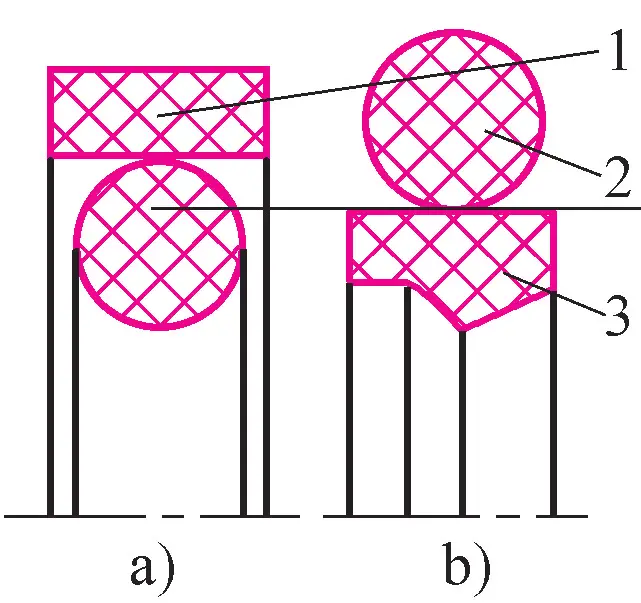
With the advancement of technology and improvement in device performance, hydraulic systems have increasingly higher requirements for sealing. Ordinary sealing rings alone can no longer meet the needs adequately. Therefore, combination sealing devices composed of two or more components, including sealing rings, have been researched and developed.
A combination sealing device composed of an O-ring and a rectangular cross-section polytetrafluoroethylene (PTFE) plastic sliding ring is shown in Figure 19a.
The sliding ring 2 fits tightly against the sealing surface, while the O-ring 1 provides elastic preload for the sliding ring. It forms a seal when the medium pressure is zero. Since the sealing gap relies on the sliding ring, not the O-ring, the friction resistance is small and stable, and it can be used for high pressures up to 40MPa.
For reciprocating motion sealing, the speed can reach 15m/s; for reciprocating swinging and spiral motion sealing, the speed can reach 5m/s. The disadvantage of the rectangular sliding ring combination seal is that it has slightly poor resistance to tilting and is prone to leakage when working in alternating high and low pressure conditions.
Figure 19b shows a combination sealing device for shafts composed of a support ring 4 and an O-ring 1. Since there is line sealing between the support ring and the sealed part 3, its working principle is similar to a lip seal. The support ring is made of a specially treated synthetic material with excellent wear resistance, low friction, and shape retention properties. The working pressure can reach 80MPa.
1—O-ring
2—Sliding ring
3—Sealed part
4—Support ring
The combination sealing device fully utilizes the advantages of both rubber sealing rings and sliding rings (support rings). It not only works reliably with low friction and good stability but also increases the service life by nearly a hundred times compared to ordinary rubber seals, finding widespread application in engineering.
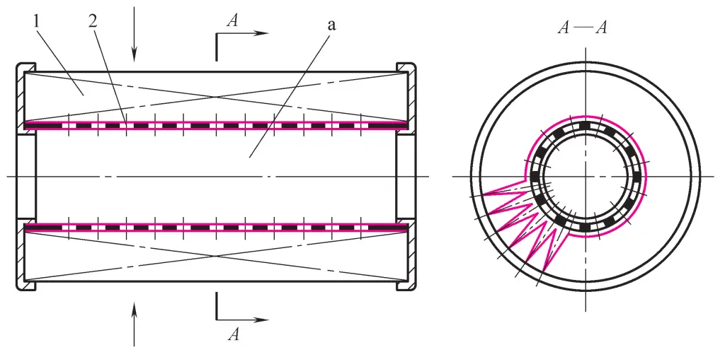
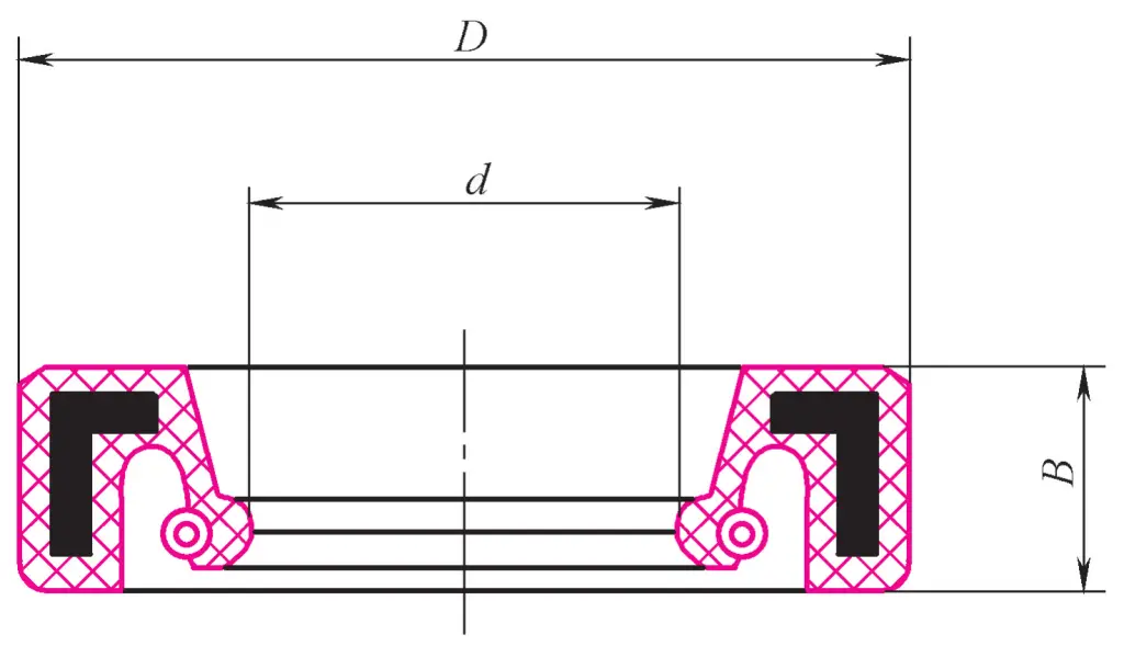
There are many forms of sealing devices for rotating shafts. Figure 20 shows a sealing ring made of oil-resistant rubber for rotating shafts. It has a right-angled circular iron skeleton supporting its interior, and a spiral spring tightens the inner edge around the shaft to achieve sealing.
This type of sealing ring is mainly used for sealing the extended shafts of hydraulic pumps, hydraulic motors, and rotary hydraulic cylinders to prevent oil leakage to the outside of the casing. Its working pressure generally does not exceed 0.1MPa, with a maximum allowable linear speed of 4-8m/s, and it must work under lubricated conditions.
With the development of material industry and the improvement and development of sealing theory, many new types of sealing elements have been researched and developed both domestically and internationally in recent years. These sealing elements have not only significantly improved in terms of physical, chemical, and sealing performance but also undergone substantial changes in structure. Their functions have also evolved from single-type to combination-type. The following introduces eight types of new sealing elements.
Figure 21 shows a star-shaped sealing element, also known as an X-shaped sealing element, suitable for bidirectional sealing of hydraulic and pneumatic actuators. The star-shaped sealing element achieves sealing through both pre-compression force and fluid pressure.
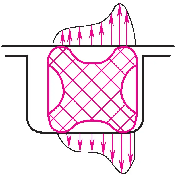
The star-shaped sealing element is suitable for linear and rotational motion sealing and static sealing applications with pressures not exceeding 40MPa, temperatures ranging from -60 to 200°C, and operating speeds not exceeding 0.5m/s.
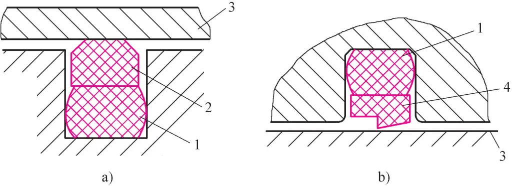
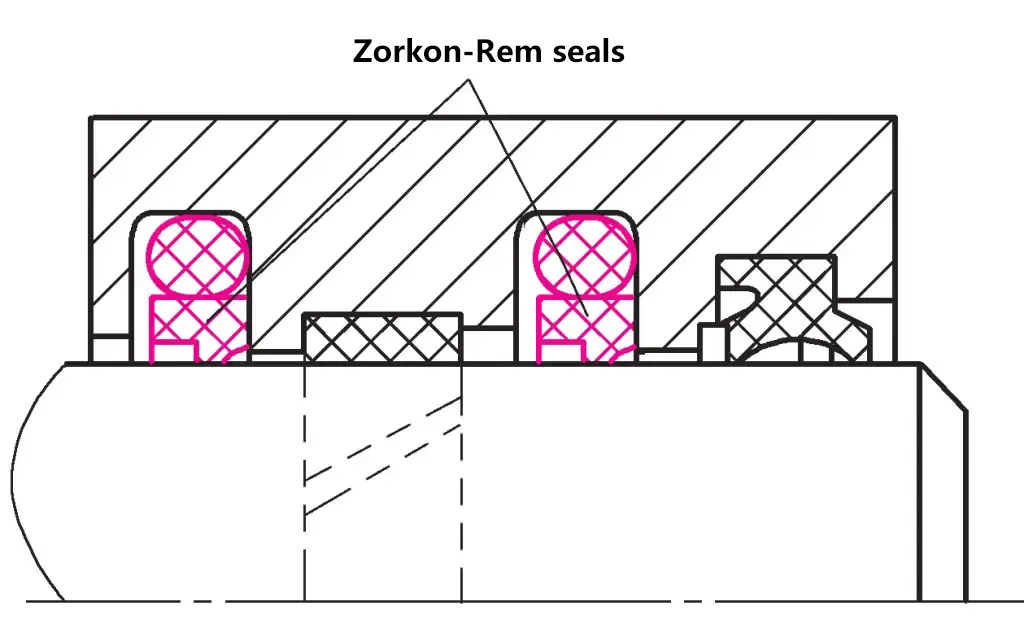
The Zurcon-Rimlip sealing element is a unidirectional sealing type that must be used in pairs to achieve bidirectional sealing. The Zurcon-Rimlip sealing element is suitable for dynamic sealing between shafts and holes with linear reciprocating motion, pressures less than 25MPa, temperatures ranging from -30 to 100°C, and operating speeds not exceeding 5m/s, as shown in Figure 22.
The Turcon-Variseal sealing element achieves sealing through the combined action of its own spring, preload force, and hydraulic pressure. It consists of a U-shaped Turcon ring and a finger-shaped stainless steel force spring, as shown in Figure 23. The characteristics of this sealing element are low friction and good wear resistance.

The Zurcon-Rimlip sealing element is suitable for dynamic sealing between shafts and holes with linear reciprocating motion, pressures not exceeding 45MPa, temperatures ranging from -70 to 260°C, and operating speeds below 15m/s.
The Turcon-Glyd Ring sealing element uses the elasticity of an O-ring to apply pressure to the sealing element for sealing, as shown in Figure 24. The characteristics of this sealing element include low friction, low starting resistance, good wear resistance, and no extrusion phenomenon.
1—Cylinder
2—Turcon-Glyd Ring seal
3—O-ring
4-Piston
Turcon-Glyd Ring seals are suitable for sealing between pistons and cylinders in linear reciprocating motion with pressures below 80MPa, temperatures from -54 to 200°C, and operating speeds below 15m/s.
Glyd Rings and Step Seals use the elasticity and pre-compression force of O-rings to press them against the inner surface of the cylinder and the outer surface of the piston rod for sealing, as shown in Figure 25. These two types of seals are suitable for dynamic sealing in hydraulic cylinders with pressures below 50MPa, temperatures from -30 to 120°C, and operating speeds below 1m/s.
a) For piston
b) For piston rod
1—Glyd Ring
2—O-ring
3—Step Seal
Wills Metal Seal Rings are solid or hollow pressurized metal rings made of various materials, mainly steel, copper, nickel alloy, Monel alloy, etc. The outer surface is often plated with cadmium, silver, gold, or PTFE.
Figure 26 shows a hollow ring Wills Metal Seal Ring, used for end face static sealing, suitable for static sealing with pressures below 1000MPa and temperatures below 800°C.
Composite Seal Rings, also known as composite gaskets, are made by integrally vulcanizing a metal ring 1 and a rubber ring 2, as shown in Figure 27. They are characterized by convenient use and reliable sealing. Suitable for static sealing between two flat surfaces with pressures below 100MPa and temperatures from -30 to 200°C.
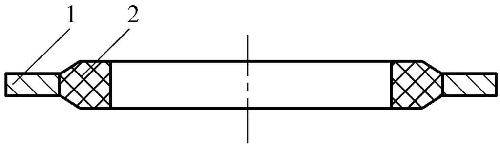
1—Metal ring
2—Rubber ring
The combination bore seal consists of an elastic seal ring 3 (nitrile rubber), two backup rings 2 (polyester elastomer), and two guide rings 1 (polyoxymethylene), forming a five-piece piston seal set, as shown in Figure 28.
Used as a bidirectional piston seal in hydraulic cylinders, it can both seal in both directions and guide and bear the radial force of the piston. It has a compact installation size and good sealing effect even at low pressures. Suitable for dynamic sealing in hydraulic cylinders with pressures below 40MPa, temperatures from -30 to 100°C, and operating speeds below 0.5m/s.
1—Guide ring
2—Backup ring
3—Elastic seal ring