The hydraulic cylinder is an actuator in the hydraulic system, and its function is to convert hydraulic energy into mechanical energy. The input to the hydraulic cylinder is the flow and pressure of the liquid, and the output is linear speed and force. The piston of the hydraulic cylinder can perform reciprocating linear motion, outputting a limited linear displacement.
I. Working Principle of Hydraulic Cylinder
Taking a double-acting single-piston rod hydraulic cylinder as an example to illustrate the working principle of the hydraulic cylinder. As shown in Figure 1, the hydraulic cylinder is mainly composed of cylinder barrel 1, piston 2, piston rod 3, end cover 4, and piston rod seal 5.
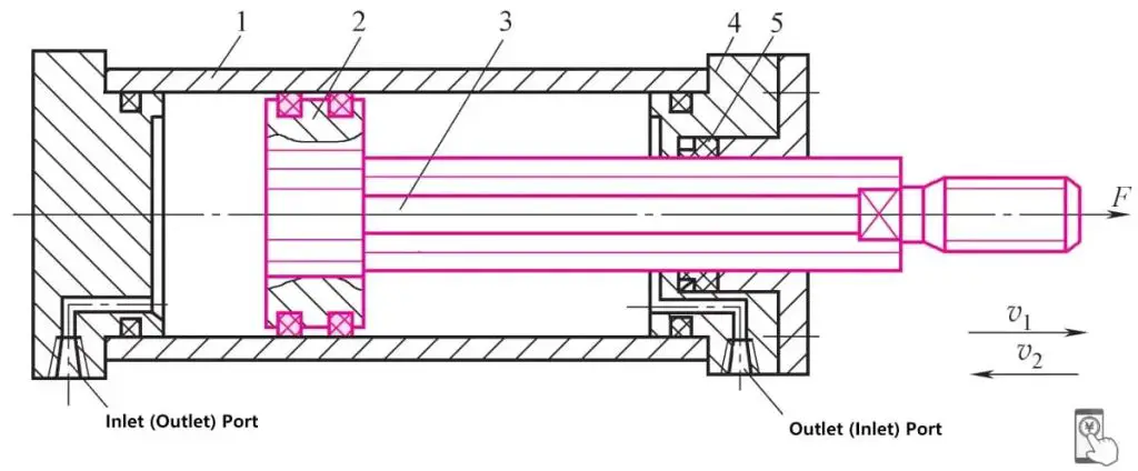
1—Cylinder barrel
2—Piston
3—Piston rod
4—End cover
5—Seal
If the cylinder barrel is fixed and hydraulic oil is continuously input into the left chamber, when the oil pressure is sufficient to overcome all the loads on the piston rod, the piston moves continuously to the right at speed v 1 , and the piston rod does work on the external environment.
Conversely, when hydraulic oil is input into the right chamber, the piston moves to the left at speed v 2 , and the piston rod also does work on the external environment. In this way, a reciprocating motion is completed. This type of hydraulic cylinder is called a fixed cylinder barrel cylinder.
If the piston rod is fixed and hydraulic oil is continuously input into the left chamber, the cylinder barrel moves to the left; when hydraulic oil is continuously input into the right chamber, the cylinder barrel moves to the right. This type of hydraulic cylinder is called a fixed piston rod cylinder.
The hydraulic cylinders discussed in this chapter, unless otherwise specified, are all examples of fixed cylinder barrel and moving piston rod hydraulic cylinders.
The oil input into the hydraulic cylinder must have pressure p and flow rate q. The pressure is used to overcome the load, and the flow rate is used to form a certain movement speed. The pressure and flow rate input into the hydraulic cylinder are the hydraulic energy input to the cylinder; the force and movement speed exerted by the piston on the load are the mechanical energy output by the hydraulic cylinder.
Therefore, the pressure p, flow rate q, output force F, and speed v input to the hydraulic cylinder are the main performance parameters of the hydraulic cylinder.
II. Classification of Hydraulic Cylinders
Due to the different uses of various machines and the different forms of motion they perform, there are many types of hydraulic cylinders, generally classified according to the oil supply method, structure, function characteristics, and use.
According to the direction of oil supply, they can be divided into single-acting cylinders and double-acting cylinders. A single-acting cylinder only inputs high-pressure oil to one side of the cylinder, relying on other external forces to make the piston return. A double-acting cylinder inputs hydraulic oil to both sides of the cylinder. The forward and reverse movements of the piston are completed by hydraulic pressure.
According to the structural form, they can be divided into piston cylinders, plunger cylinders, swing cylinders, and telescopic sleeve cylinders.
According to the form of the piston rod, they can be divided into single-piston rod cylinders and double-piston rod cylinders.
According to the special uses of the cylinder, they can be divided into tandem cylinders, booster cylinders, speed-increasing cylinders, step cylinders, etc. These types of cylinders are not a single cylinder barrel but are combined with other cylinder barrels and components, so from a structural point of view, these cylinders are also called combined cylinders. According to the pressure used by the hydraulic cylinder, they can be divided into low-pressure hydraulic cylinders, medium-pressure hydraulic cylinders, high-pressure hydraulic cylinders, and ultra-high-pressure hydraulic cylinders.
For machine tool machinery, medium and low-pressure hydraulic cylinders are generally used, with a rated pressure of 2.5 to 6.3 MPa; for construction machinery, engineering machinery, and aircraft, medium and high-pressure hydraulic cylinders are mostly used, with a rated pressure of 10 to 16 MPa; for machinery like hydraulic presses, high-pressure hydraulic cylinders are mostly used, with a rated pressure of 25 to 31.5 MPa.
The classification of hydraulic cylinders is shown in Table 1.
Table 1 Classification of Hydraulic Cylinders
| Name | Symbol | Working Characteristics | ||
| Single-acting hydraulic cylinder | Piston cylinder | 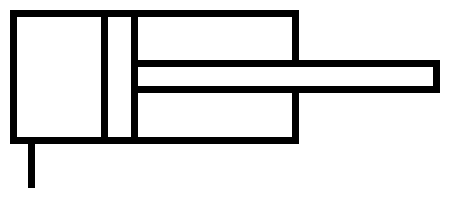 | Unidirectional hydraulic drive, return by self-weight, spring, or other external forces | |
| Plunger cylinder | 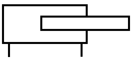 | The plunger is thick, bears force well, and is driven unidirectionally by hydraulic pressure | ||
| Telescopic sleeve cylinder | 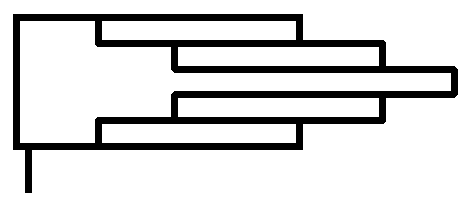 | Driven by hydraulics, it is pushed out section by section from large to small, and then retracted section by section from small to large by its own weight. | ||
| Double-acting hydraulic cylinder | Single piston rod | Standard cylinder | 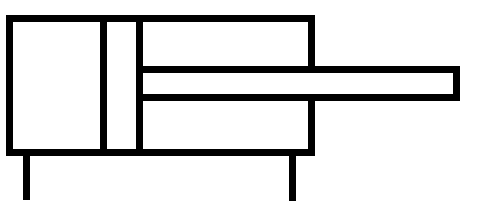 | The piston moves under hydraulic pressure in both directions, does not decelerate at the end of the stroke, and the force and speed of movement in both directions are different. |
| Non-adjustable cushioning cylinder | 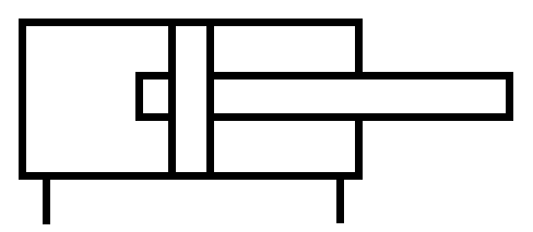 | The piston moves under hydraulic pressure in both directions, decelerates at the end of the stroke, and the deceleration value is not adjustable. The force and speed of movement in both directions are different. | ||
| Adjustable cushioning cylinder | 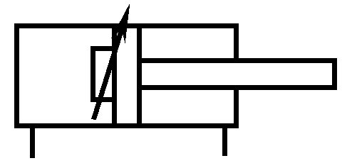 | The piston moves under hydraulic pressure in both directions, decelerates at the end of the stroke, and the deceleration value is adjustable. The force and speed of movement in both directions are different. | ||
| Differential cylinder | 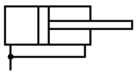 | Can speed up the intake of oil in the rodless chamber, but the thrust is correspondingly reduced. | ||
| Double piston rod | Standard cylinder | 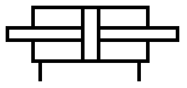 | The piston moves under hydraulic pressure in both directions, does not decelerate at the end of the stroke, and the force and speed of movement in both directions are the same. | |
| Double-speed cylinder | 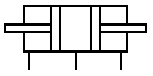 | Two pistons move simultaneously in opposite directions. | ||
| Non-adjustable cushioning cylinder | 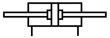 | The piston moves under hydraulic pressure in both directions, decelerates at the end of the stroke, and the deceleration value is not adjustable. The force and speed of movement in both directions are the same. | ||
| Adjustable cushioning cylinder | 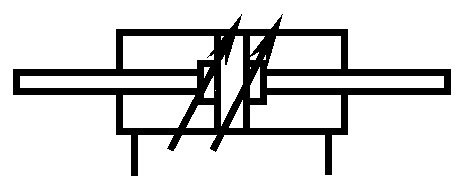 | The piston moves under hydraulic pressure in both directions, decelerates at the end of the stroke, and the deceleration value is adjustable. The force and speed of movement in both directions are the same. | ||
| Telescopic sleeve cylinder | 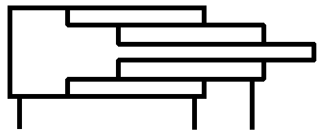 | Double-acting hydraulic drive, the extension and retraction procedure is the same as that of a single-acting telescopic sleeve cylinder. | ||
| Combination cylinder | Booster cylinder | 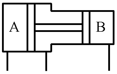 | Driven by oil intake in chamber A, outputs high-pressure oil in chamber B. | |
| Tandem cylinder | 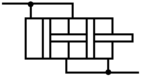 | Used in situations where the diameter of the cylinder is restricted but the length is not, allowing for greater thrust. | ||
| Multi-position cylinder | 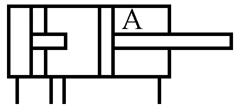 | By opening different oil inlets as needed, piston A can have three positions. | ||
| Stepping cylinder | 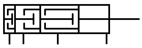 | Several piston strokes are arranged in binary order. By opening different oil inlets as needed, the piston can move different distances. | ||
| Rack and pinion cylinder | 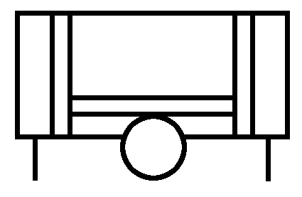 | Converts the reciprocating linear motion of the piston into the reciprocating rotary motion of the gear. | ||

