Hydraulic Press Brake vs. Folding Machine: A Comprehensive Guide
Why do some industries prefer hydraulic press brakes, while others opt for folding machines? The choice often boils down to…
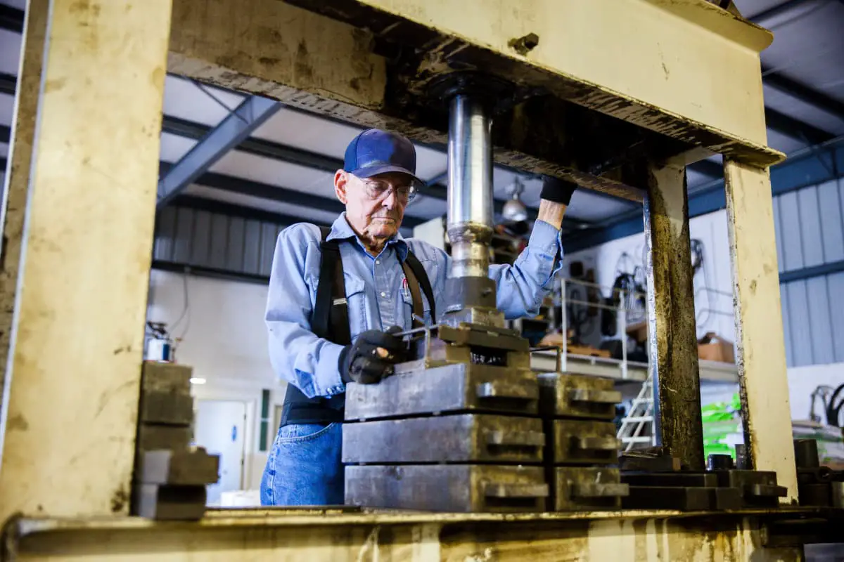
A hydraulic press is a machine that uses liquid as a medium to transfer energy to achieve various forging processes.
The hydraulic press is made according to Pascal’s principle, and its working principle is shown in Figure 1-1-1. Two closed cavities filled with working fluid and having pistons are connected by pipes. When a force P 1 is applied on the small piston 1, the pressure of the liquid is p=P 1 /A 1 , where A 1 is the cross-sectional area of piston 1.
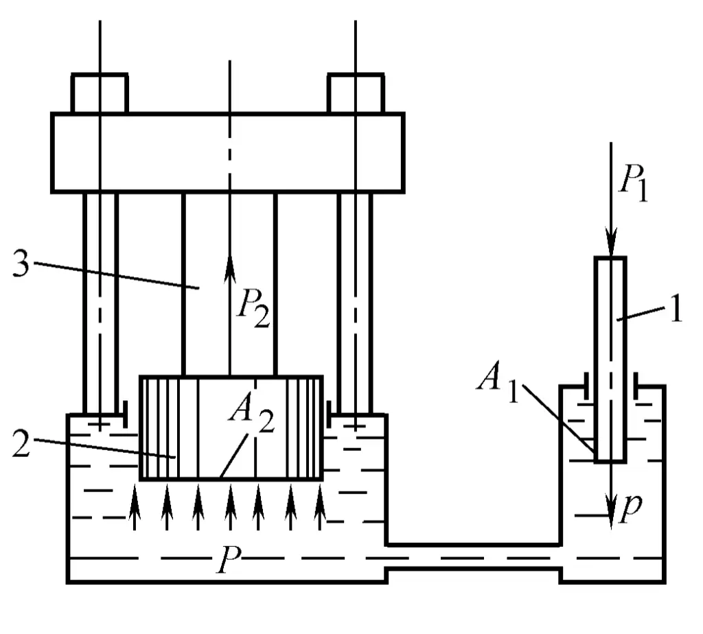
1—Small Piston
2—Large Piston
3—Workpiece
According to Pascal’s principle: In a sealed container, the liquid pressure is completely equal in all directions, and the pressure p will be transmitted to every point inside the cavity, thus generating an upward force P 2 on the large piston 2, causing the workpiece 3 to deform.
P2=P1 A2/A1
Where A 2 refers to the cross-sectional area of piston 2.
A hydraulic press generally consists of two parts: the body (mainframe) and the hydraulic system.
The most common structure of a hydraulic press body is shown in Figure 1-1-2. It consists of an upper crossbeam 1, a lower crossbeam 3, four columns 2, and 16 internal and external nuts forming a closed frame, which bears all the working load. The working cylinder 9 is fixed on the upper crossbeam 1, and it contains a working piston 8, which is connected to the moving crossbeam 7. The moving crossbeam is guided by four columns and reciprocates between the upper and lower crossbeams. The lower surface of the moving crossbeam is usually fixed with an upper die (upper anvil), while the lower die (lower anvil) is fixed on the worktable of the lower crossbeam 3.
When high-pressure fluid enters the working cylinder and acts on the working plunger, a large force is generated, pushing the plunger, the moving crossbeam, and the upper mold downward, causing plastic deformation of the workpiece 5 between the upper and lower molds. The return cylinder 4 is fixed on the lower crossbeam, and during the return, the working cylinder passes low-pressure fluid, high-pressure fluid enters the return cylinder, pushing the return plunger 6 and the moving crossbeam upward, returning to the original position, completing a work cycle.
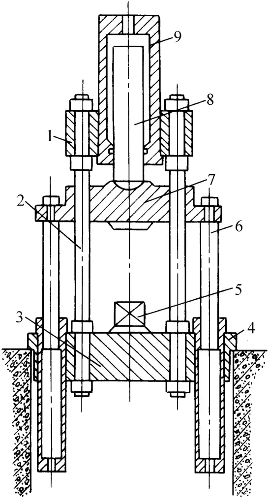
1—Upper crossbeam
2—Column
3—Lower crossbeam
4—Return cylinder
5—Workpiece
6—Return plunger
7—Moving crossbeam
8—Working plunger
9—Working cylinder
Many small and medium-sized hydraulic presses use piston-type working cylinders, as shown in Figure 1-13. When the upper and lower chambers of the piston cylinder alternately admit high-pressure fluid, the working stroke and return stroke can be successively achieved without the need for a separate return cylinder.
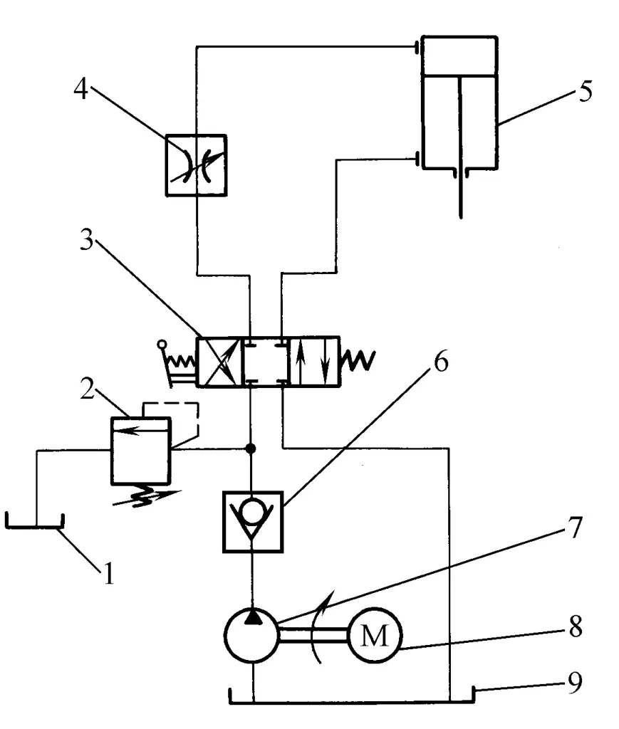
1—Oil tank
2—Overflow valve
3—Directional valve
4—Throttle valve
5—Hydraulic cylinder
6—Check valve
7—Pump
8—Motor
9—Fuel tank
The working cycle of a hydraulic press generally includes stopping, filling stroke, working stroke, and return stroke. The different strokes mentioned are achieved by the action of various functional valves in the hydraulic control system.
The hydraulic system of the hydraulic press includes various high and low pressure pumps, high and low pressure vessels (fuel tanks, filling tanks, accumulators, etc.), valves, and corresponding connecting pipes. Its transmission methods can be divided into direct pump drive and pump-accumulator drive.
Direct pump drive involves the pump directly supplying high-pressure fluid to the working cylinder of the hydraulic press and other auxiliary devices. The simplest hydraulic system is shown in Figure 1-1-3, which is achieved through a three-position four-way slide valve, namely the directional valve 3, to realize various strokes.
The directional valve 3 is in the straight-through position, the lower chamber of the piston-type hydraulic cylinder 5 is connected to the low-pressure oil tank, the moving crossbeam descends from the upper stop position by its own weight, the fluid in the lower chamber is discharged back to the oil tank, and the working fluid supplied by the pump enters the upper chamber of the piston cylinder through the directional valve 3. Since the resistance of the moving crossbeam is very small at this time, the pump works under low pressure, mainly to transport the working fluid to the upper chamber of the piston cylinder to compensate for the volume vacated by the downward movement of the moving crossbeam, until the upper die (upper anvil) contacts the workpiece, completing the filling stroke.
The directional valve 3 remains in the straight-through position. When the upper anvil contacts the workpiece, the resistance increases, the downward speed of the moving beam slows down, and the outlet pressure of the pump (commonly referred to as pressure in engineering, referred to as pressure below unless otherwise specified) increases accordingly. High-pressure fluid enters the upper chamber of the piston cylinder and acts on the piston, applying pressure to the workpiece through the moving crossbeam, while the fluid in the lower chamber of the piston cylinder continues to be discharged back to the oil tank.
The directional valve 3 is switched to the cross-communication position, high-pressure liquid enters the lower chamber of the piston cylinder, driving the moving crossbeam upward, and the liquid in the upper chamber of the piston cylinder is discharged back to the tank.
The directional valve 3 is in the middle position, the liquid in the upper and lower chambers of the piston cylinder is sealed within the cylinder, the liquid in the lower chamber supports the weight of the moving parts, stopping at any required position, completing a work cycle.
The pump and accumulator transmission adds an accumulator to the hydraulic system, whose main function is to store high-pressure liquid to even out the pump load. It generally uses high-pressure gas to maintain the pressure of the working fluid.
When the hydraulic press does not need a large amount of high-pressure liquid, such as during return or stop, the high-pressure liquid supplied by the pump can be partially or completely stored in the accumulator, and when the hydraulic press needs a large amount of high-pressure liquid, it is supplied by both the pump and the accumulator.
The schematic diagram of the hydraulic control system for the pump and accumulator transmission is shown in Figure 1-1-4, which is achieved through a rocker-type four-valve distributor for various strokes:
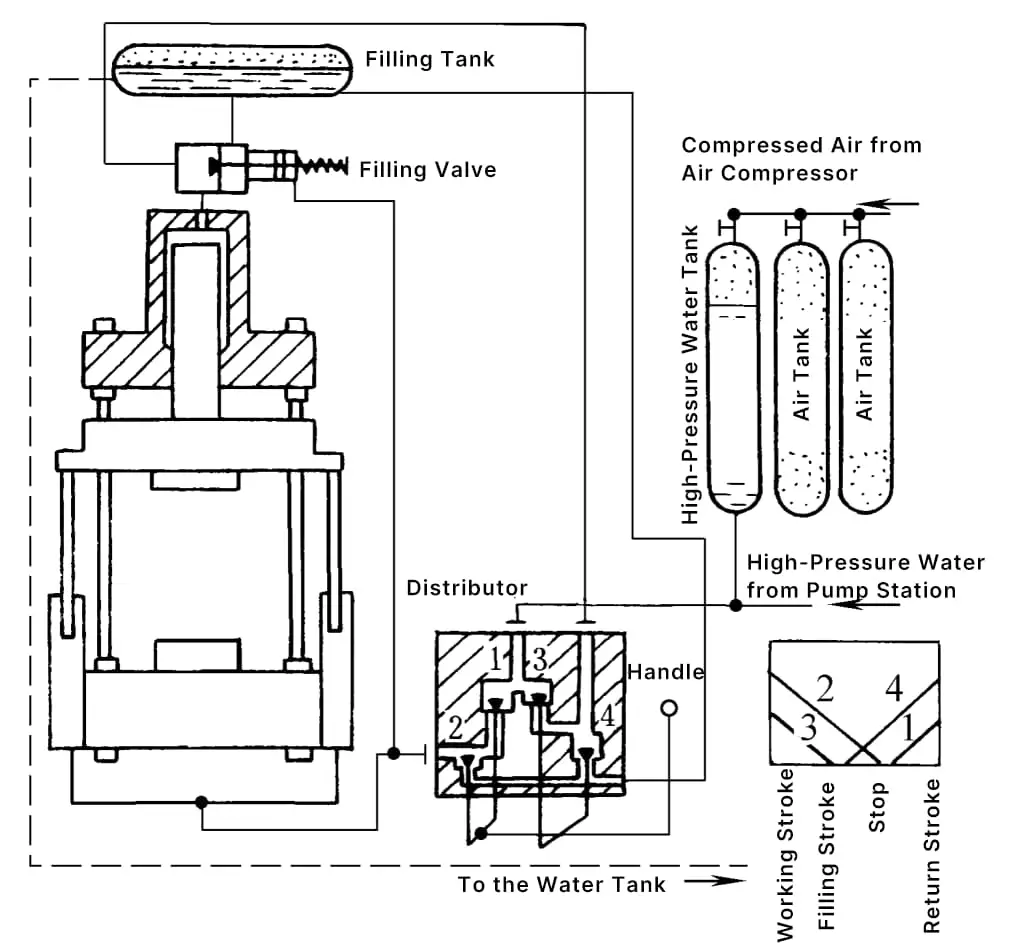
1, 3—Inlet Valve
2, 4—Drain Valve
At the start of the work cycle, the return cylinder drain valve 2 opens, the moving crossbeam descends by its own weight from the upper stop position, and the fluid in the return cylinder is drained back to the low-pressure tank or charging tank.
The fluid pressure inside the working cylinder decreases, and due to the compressed air at (4~6)×10 5 Pa in the upper part of the charging tank, the charging valve is pushed open by the pressure difference between the working cylinder and the charging tank. Under the action of low-pressure air or gravity, a large amount of fluid flows into the working cylinder, realizing the charging stroke of the moving crossbeam downward until the upper anvil (upper mold) contacts the workpiece, the movement of the moving beam stops, and the pressure difference between the working cylinder and the charging tank disappears, the charging valve automatically closes under the action of the spring.
To ensure a smooth charging stroke, towards the end of the charging stroke, the opening height of the return cylinder drain valve should be reduced to decelerate the moving crossbeam and minimize impact and vibration.
After the charging stroke ends, the charging valve should be completely closed, and the return cylinder remains at low pressure. When the working cylinder inlet valve 3 opens, high-pressure fluid from the high-pressure pump or accumulator enters the working cylinder through the charging valve chamber and acts on the plunger, applying pressure to the workpiece through the moving crossbeam. At this time, the return cylinder drain valve 2 continues to open for drainage.
After the working stroke ends, the working cylinder inlet valve 3 closes first, followed by the opening of the working cylinder drain valve 4, releasing the pressure of the high-pressure fluid in the working cylinder and pipes. Then, the return cylinder drain valve 2 closes, the return cylinder inlet valve 1 opens, allowing high-pressure fluid to pass through the charging valve actuator, forcibly opening the charging valve. The moving crossbeam moves upward under the action of the high-pressure fluid in the return cylinder, forcing a large amount of fluid in the working cylinder into the charging tank.
When the moving beam reaches the stop position, the water inlet valve 1 of the return cylinder closes, at this time the drainage valve 2 of the return cylinder remains closed, while the drainage valve 4 of the working cylinder continues to open, the working cylinder still passes low pressure, and the moving beam is supported by the liquid sealed in the return cylinder, so the moving beam can stop at any position in the stroke.
During direct pump drive, the liquid pressure supplied by the pump changes with the deformation resistance of the workpiece and is not constant. The travel speed of the moving beam depends on the pump’s supply of liquid and is independent of the deformation resistance of the workpiece.
During pump and accumulator drive, the pressure of the liquid supplied by the pump and accumulator is maintained within the fluctuation range of the accumulator pressure, which is about 10% to 15% of the maximum pressure. The speed of the working stroke decreases with the increase in deformation resistance of the workpiece.
Sometimes, to supply the hydraulic press with higher pressure working fluid, a booster is added between the working cylinder and the corresponding valve. The schematic structure of the booster is shown in Figure 1-1-5. Cylinder 1 and the lower beam are cast as one, forming a load-bearing frame with the upper beam 6 through column 7.
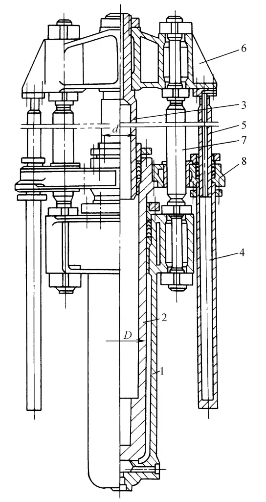
1—Cylinder
2, 3—Hollow plunger
4—Return cylinder
5—Return plunger
6—Upper beam
7—Column
8—Moving Beam
Cylinder 1 contains a hollow plunger 2, which itself is the working cylinder for hollow plunger 3. When high-pressure fluid enters cylinder 1, it pushes hollow plunger 2 upwards, forcing the pressurized fluid out from hollow plunger 3. The return is achieved by the return cylinder 4, and the boost ratio is the square of the ratio of the diameters of the large and small plungers.
Hydraulic presses primarily use two types of working media: those using emulsion are generally called hydraulic presses, and those using oil are called oil hydraulic presses, collectively referred to as hydraulic presses.
The emulsion is made by mixing 2% emulsified fat and 98% soft water. It should have good anti-corrosion and anti-rust properties, and a certain lubricating effect. Emulsion is inexpensive, non-flammable, and does not easily contaminate the site, hence it is widely used in hydraulic presses with large fluid consumption and those used for thermal processing.
The most widely used fluid in oil hydraulic presses is hydraulic oil, although sometimes turbine oil or other types of machine oil are used. Oil is better than emulsion in terms of anti-corrosion, anti-rust, and lubrication properties. Oil has a higher viscosity and is easier to seal. Therefore, in recent years, the use of oil as a working medium has been increasing, but oil is flammable, costly, and can contaminate the site.