I. Working Principle of Hydraulic Transmission
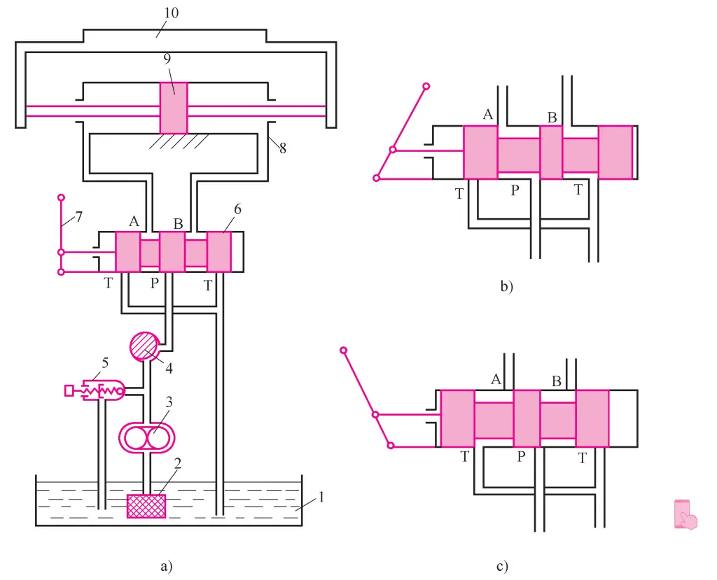
Figure 1 is a diagram of a simple machine tool’s hydraulic transmission system. The hydraulic cylinder 8 is fixed on the bed, and the piston 9, along with the piston rod, drives the worktable 10 to move linearly back and forth. The motor drives the hydraulic pump 3 to rotate, and the hydraulic pump 3 draws oil from the oil tank 1 through the filter 2. The oil flows through the throttle valve 4 to the directional valve 6. When the handle 7 is in the position shown in Figure 1-1a, P is not connected to A, B, or T, so the hydraulic cylinder 8 does not receive oil, and the worktable stops.
1—Oil Tank
2—Filter
3—Hydraulic Pump
4—Throttle Valve
5—Relief Valve
6—Directional Valve
7—Handle
8—Hydraulic Cylinder
9—Piston
10—Worktable
If the handle 7 is pushed to the position shown in Figure 1b, the oil flows from P→A→left chamber of hydraulic cylinder 8; right chamber of hydraulic cylinder 8→B→T, and the worktable 10 moves to the right.
If the handle 7 is pushed to the position shown in Figure 1c, the oil flows from P→B→right chamber of hydraulic cylinder 8; left chamber of hydraulic cylinder 8→A→T, and the worktable 10 moves to the left.
It can be seen that by setting the directional valve 6 and positioning its spool in different positions, the oil path can be changed, allowing the hydraulic cylinder to continuously change direction, thereby achieving the reciprocating motion of the worktable.
The speed of the worktable v is adjusted through the throttle valve 4. The function of the throttle valve is to control the flow rate of the oil passing through it by changing the size of its opening, thereby controlling the speed of the worktable.
When the worktable is moving, it needs to overcome resistance, including cutting force and friction between the surfaces of relatively moving parts. These resistances are overcome by the pressure energy of the oil output by the hydraulic pump. Depending on the working conditions, the pressure of the oil output by the hydraulic pump should be adjustable.
Additionally, in general, the oil discharged by the hydraulic pump is often more than what the hydraulic cylinder needs. The excess oil flows back to the oil tank through the relief valve 5. The filter 2 is a mesh filter that filters the oil.
From the above analysis, it can be seen:
- Hydraulic transmission relies on the pressure energy of moving liquid to transmit power, which is different from “hydraulic drive” that relies on the kinetic energy of liquid to transmit power.
- When the hydraulic system is working, the hydraulic pump converts mechanical energy (from the motor) into pressure energy; the actuating elements (hydraulic cylinder or hydraulic motor) convert pressure energy into mechanical energy.
- The oil in the hydraulic transmission system works under regulated and controlled conditions.
- The hydraulic transmission system must meet the requirements of the driven moving parts in terms of force and speed.
- Hydraulic transmission uses pressurized liquid as the working medium to transmit signals and power.
II. Components of the Hydraulic Transmission System
From the above analysis, it can be seen that the hydraulic transmission system consists of five parts:
1. Power Unit
It converts the input mechanical energy into the pressure energy of the oil. The most common is the hydraulic pump, which provides hydraulic oil for the hydraulic system, enabling the entire system to operate.
2. Actuating Unit
Convert the pressure energy of the oil into mechanical energy and perform work externally, causing the moving parts to move, such as hydraulic cylinders and hydraulic motors.
3. Control and Regulation Devices
These are devices that control the pressure, flow, and flow direction of the oil in the hydraulic system. In the hydraulic transmission system shown in Figure 1-1, hydraulic components such as relief valves, throttle valves, and directional valves belong to this category.
4. Auxiliary Devices
These are other devices besides the aforementioned three, such as the oil tank, filter, and oil pipe shown in Figure 1. They play an important role in ensuring the hydraulic system works reliably, stably, and durably.
5. Working Medium
Hydraulic oil or other synthetic liquids.

