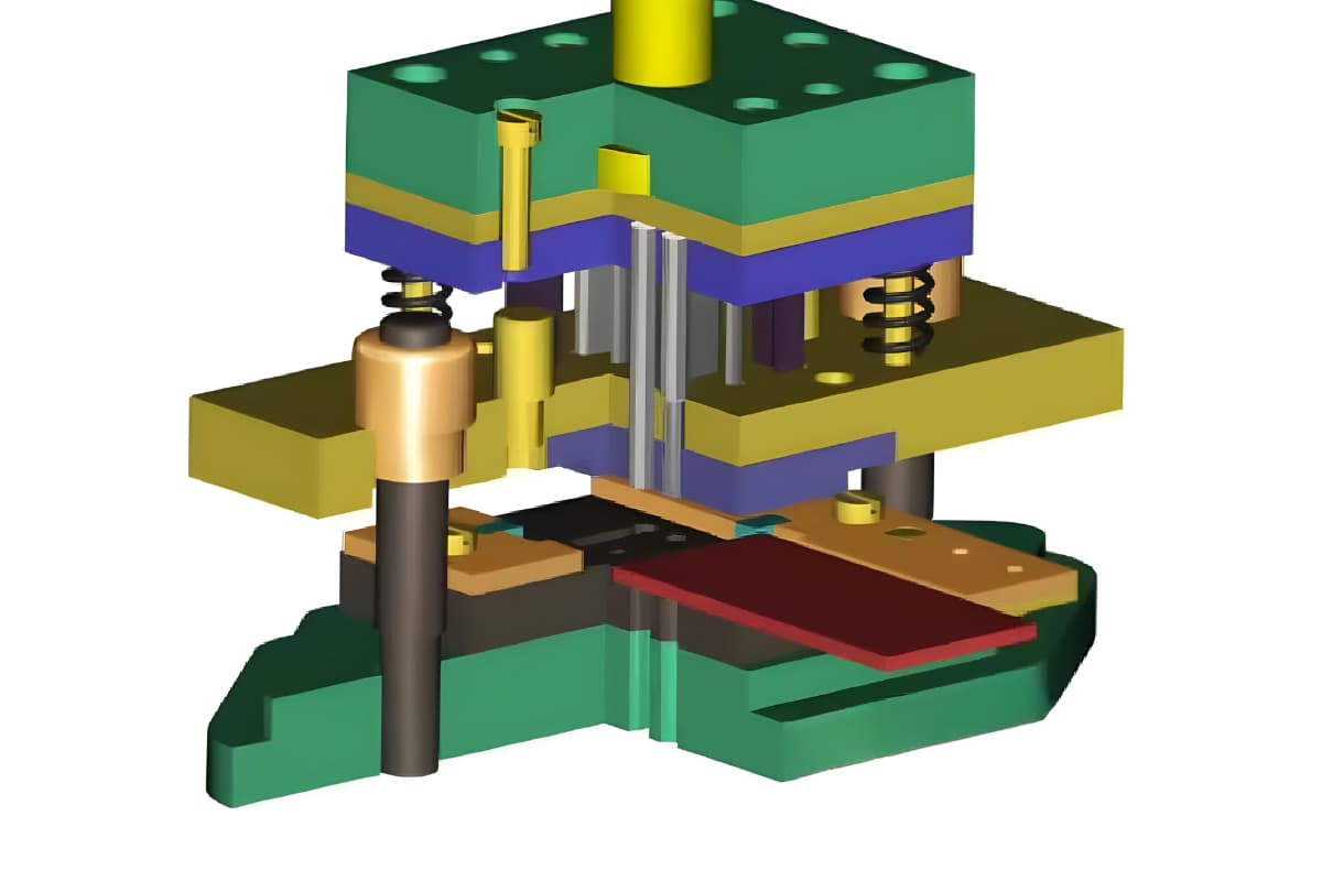
Die assembly involves arranging parts that meet the technical requirements of the design drawings in a specific order and method, according to the structural features and technical conditions of the die.
These parts, after being processed for compatibility, are assembled into a mold that meets operational standards. Thus, die assembly is a critical process in mold manufacturing. The quality of die assembly directly affects the stamping quality of the parts produced, as well as the maintenance, use, and lifespan of the mold.
Before beginning assembly, it is essential to thoroughly study the mold drawings, devise a reasonable assembly plan based on its structural characteristics and technical conditions, and meticulously inspect each part provided. Parts with a specific orientation should be marked before assembly to ensure error-free installation according to the established steps.
A die assembled following the devised plan should meet the following basic requirements:
1) The assembled die should slide smoothly and flexibly along the guide posts without any stiffness.
2) All punch components must be perpendicular to the assembly base surface of the fixed plate.
3) The clearance between the punch and die must meet the requirements specified in the drawings and be evenly distributed. The working stroke of the punch or die should comply with the technical conditions.
4) The relative positions of locating and material-blocking devices must conform to the drawing specifications. The spacing between the guide plates of the blanking die should be consistent with the drawings; the guide surfaces should be parallel to the centerline of the material feeding direction of the die. For guide plates with side-pressure devices, the side-pressure plate should slide smoothly and work reliably.
5) The relative positions of the material ejection and knockout devices must meet design requirements, with the over-height within the permissible range, and no tilting or unilateral deviation on the working surface to ensure timely and smooth ejection of parts or scrap.
6) The scrap holes or discharge channels must be clear to ensure free ejection of parts or scrap.
7) Standard parts should be interchangeable; the fit between fastening bolts, locating pins, and their respective holes should be normal and in good condition.
8) The installation dimensions of the mold on the press must meet the requirements of the selected equipment. Lifting components should be safe and reliable.
General Mold Assembly Procedure
The key to mold assembly is ensuring that the male and female dies installed on the upper and lower mold bases, along with their associated parts, align correctly when the mold closes. This alignment must meet the design specifications to guarantee the mold functions correctly and produces workpieces that meet product standards.
To this end, all parts entering assembly must comply with the processing requirements specified for each component in the assembly process. For instance, the fixed plate for multiple male dies must have relative positional accuracy and pitch precision between its various shaped holes to match the female die and stripper plate.
The bolts and dowel pins on the spacer plate should leave a generous clearance in the through-holes, allowing for drilling according to the specified dimensions on the blueprint. After hardening, the upper and lower surfaces must be precisely ground flat. The integral female dies mounted on the upper or lower mold bases, besides having their shaped holes machined to blueprint specifications, should also have bolt and dowel pin holes processed.
After heat treatment and precision machining, these are ready for assembly. The mold base and guide plate that are to be secured to these must have their screw and dowel holes drilled and reamed to match the corresponding holes on the female die during assembly.
Regardless of the type and structural characteristics of the mold, and although the methods and sequence of assembly may differ, the principles of assembly to be followed are the same.
The first step in assembling a mold is to select a reference part to serve as the assembly benchmark for the mold. Other mold parts are then assembled progressively based on this reference. The choice of reference part depends on the structural characteristics of the mold. For a guide plate mold, the guide plate that also serves as the stripper should be the assembly reference part.
For molds guided by guide posts, the female die is commonly used as the assembly reference. For blanking and piercing compound molds, the ejector plate is chosen as the assembly reference, with the precondition that the ejector plate’s force center aligns with the center of the mold shank.
Once the reference part is chosen, the various mold components are first assembled into subassemblies based on their individual connections (such as installing the mold shank on the upper mold base or securing the male die on the fixed plate). Then, using the reference part as the assembly benchmark, the total assembly of the mold is completed.
Single-Operation Die Assembly
Single-operation punching dies come in two types: those without and with guide devices. For punching dies without guide devices, the upper and lower dies are assembled separately according to the drawing requirements.
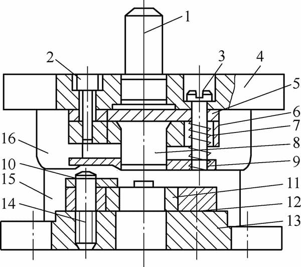
1 – Handle, 2 – Hex Socket Cap Screw, 3 – Stripper Screw, 4 – Upper Die Plate, 5 – Spacer, 6 – Punch Retainer Plate, 7 – Spring, 8 – Punch, 9 – Stripper Plate, 10 – Locator Plate, 11 – Die, 12 – Die Bushing, 13 – Lower Die Shoe, 14 – Screw, 15 – Guide Post, 16 – Guide Bushing.
The clearance between the punch and die is adjusted after the die is mounted on the press. However, before assembly, it is crucial to insert the punch into the die to check if the clearance is appropriate and uniform around the perimeter. Typically, the die is used as a reference point for single-operation punching dies, after which the upper die is fitted and the clearance is adjusted accordingly.
For punching dies with guide devices, the assembly begins with the selection of a reference part. Assuming the use of EDM wire cutting for machining the die orifices, the assembly steps for a single-operation punching die with guide devices are as follows:
1. Assemble the die set
1) The assembly of the die set mainly involves the guide pillars and bushings. Most die sets currently use an interference fit between the guide pillars, bushings, and the die holder, as shown in Figure 2-22.
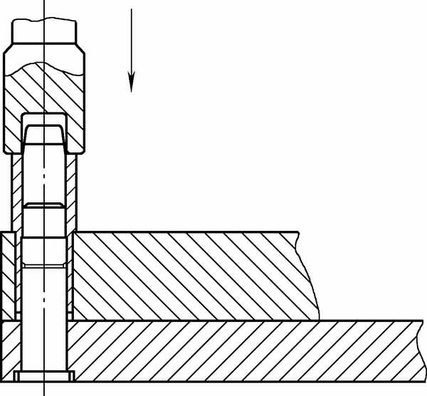
2) Another method is to have an interference fit only between the lower die holder and the guide pillars. The mounting surface of the bushings is shaped to facilitate adhesion. During assembly, the guide pillars are installed first and their verticality is checked. Then, using gauge blocks to level the upper die holder, adhesive is injected between the die holder hole and the bushings to complete the die set assembly.
After assembly, the die set must be inspected for parallelism and motion accuracy. The non-parallelism of the lower surface of the upper die holder to the lower die holder should not exceed 0.05mm per 300mm for precision class I die sets and 0.08mm per 300mm for precision class II die sets. Its motion accuracy should not exceed 0.02mm per 100mm.
2. Install the shank
The shank installation is depicted in Figure 2-23, with the following specific steps:
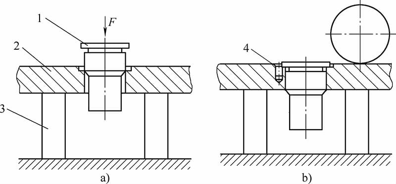
a) Die Handle Assembly b) Grinding the End Face
1 – Die Handle 2 – Upper Die Seat 3 – Equal Height Block 4 – Dowel Pin
1) Check the die shank stop height; it should be 0.5 to 1mm less than the depth of the upper die holder stop. The die shank stop diameter should be 0.5 to 1mm smaller than that of the die holder stop.
2) Use a square to check the perpendicularity of the die shank to the upper die plate and adjust accordingly. On a manual hydraulic press, press the die shank into the upper die plate.
3) Install the die shank set screws.
3. Installing the Convex Punch
Taking the wire-cutting through-type punch die as an example:
1) Remove the EDM sludge from the punch die mounting plate hole.
2) Chamfer the back of the punch die mounting plate along the cavity perimeter by (0.5 to 1.5) mm at a 45° angle, with the size of the chamfer depending on the force exerted on the mold.
3) Chamfer the cutting edge of the punch die by approximately 0.25mm at a 45° angle along the contour line.
4) Lightly sand or file the wire-cutting marks on the cutting edge of the punch die to facilitate its entry into the mounting plate. Leave a section at the end unrefined, with its length slightly greater than or equal to the thickness of the mounting plate.
5) Place a spacer block, taller than the punch die, under the mounting plate, then press the punch die into the mounting plate. This task should be performed in stages; once the punch die can stand upright in the mounting plate, measure the perpendicularity. Repeat the measurement at one-third and one-half insertion depths, correcting any misalignment promptly. Continue after ensuring accuracy.
6) For multiple or small-sized punch dies, align the stripper plate with the die cavity and use it to guide the punch dies into place.
7) Stop pressing the punch die into the mounting plate when the remaining tail length is 3 to 5mm. Heat the edge of the punch die tail with an oxy-acetylene flame and quickly tap with a small hammer to swell the heated part. After cooling completely, press the punch die fully into the mounting plate, as shown in Figure 2-24.
8) Use gauge blocks to level the surface, grinding the upper surface and the tail end of the punch die flat based on the lower surface of the mounting plate as a reference.
Using the surface of the fixed plate as a reference, fit the stripper plate over the punch (this is especially necessary when the punch is small), ensuring that its working surface is slightly lower than the punch. Grind the chamfered edge of the punch’s working end face until the cutting edge is sharp.
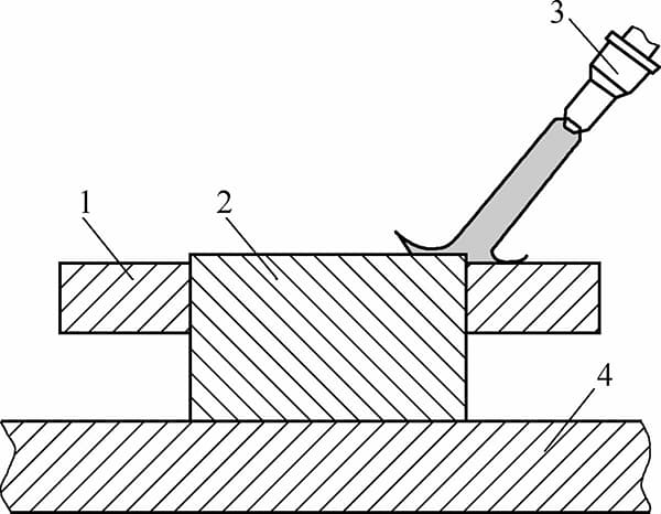
1—Punch Retainer Plate 2—Punch 3—Oxygen Cutting Torch 4—Anvil Block
4. Installing the Concave Die
1) Determine the center point of the stripper plate and align it with the center point of the die shank; process the base plate’s scrap hole contour based on the cavity of the die, securing it with bolts through the die.
2) Verify the alignment of the die with the base plate’s scrap hole contour, ensuring no misalignment occurs. Once confirmed, tighten with bolts, drill and ream through the die for the positioning pins, and insert the locating dowels.
5. Installing the Top Punch
Place the lower die flat, cover the die with a plastic film of thickness corresponding to the side clearance, insert shims to equal height, lift the upper die holder, align the punch with the die, and gently tap with a hammer handle.
If the punch enters the die smoothly by 5-6mm, the clearance between the punch and die is preliminarily considered appropriate. Then, clamp the upper die holder, punch pad, and punch retainer plate together with a C-clamp, remove the upper die, drill through the punch retainer plate or the die (if inverted) into the upper die holder, and preliminarily connect the two parts with bolts.
If the guide posts directly pass through the die and stripper plate, and the guide bushings are installed on the punch retainer plate, and the cavities and locating pin holes for the die and punch retainer plate are processed based on the guide post holes during wire cutting, then during assembly, it is only necessary to ensure the verticality of the punch to the retainer plate, and the steps for squaring and adjusting the upper die holder can be omitted.
It should be noted that when manufacturing dies with complex shapes, high precision requirements, or material thicknesses less than 0.25mm, it is often necessary to check the fit between the punch and die after machining each pair.
6. Checking the Punch-Die Clearance
Replace the plastic film, connect the upper and lower die holders via the guide posts, and if the punch automatically slides into the die, the clearance is considered appropriate, and work can proceed to the next step. Alternatively, lay the die flat, tap with a wooden mallet, and if the force does not change during insertion and the plastic film is not cut after withdrawal, the clearance is also considered appropriate.
If the clearance is not suitable, insert the upper die into the die until the punch surface barely enters the working surface of the die, and check the punch-die clearance using the light transmission method; turn the assembled die over, clamp the shank in a bench vise, shine a flashlight, and observe the gap size and uniformity through the scrap hole of the lower die holder.
Adjust to even out the gap, and if any unevenness is observed, gently tap the side of the retainer plate with a hammer to change the position of the punch in the upper die until a uniform gap is achieved.
7. Inserting the Dowels
Once the gap is uniform, tighten the screws, drill and ream the holes for the upper die locating dowels, and insert the dowels.
8. Installing the Stripper Plate
Fit the stripper plate over the punch, check the sliding clearance between the two, and ensure its movement is smooth. Then install the springs and suspend the stripper plate on the upper die, adjusting the suspension bolts so that the stripper plate surface is 0.5-1mm above the punch working surface.
Lastly, check the travel of the suspension bolts to ensure a 3-5mm clearance from the top end to the upper surface of the die holder at the end of the punching stroke.
9. Installing the Feeding Device and Stop Pins
After ensuring there are no issues, correctly install the feeding device and stop pins.
10. Test Cutting and Adjustment
Use paper or scrap cardboard of the same thickness as the punched material, place it on the die surface, and lightly tap the die shank with a soft metal rod or the wooden handle of a mallet for a test cut.
Check the burr size and uniformity on the test paper; if the burr is inconspicuous or present but uniform and of consistent height around the perimeter, the assembly is correct. Preferably use coarse-fibered rough paper, with printer paper as a secondary option, avoiding coated paper.
11. Stamping the Number
Stamp the number as required by the manufacturer.
12. Trial Punching
After trial punching on the machine, if no abnormalities occur, lubricate the guide posts and bushings in preparation for production or storage.
Compound Die Assembly
The structure of a compound die is compact, requiring high precision in the machining of its components. It is commonly used for punching thinner materials, with relatively small clearances between the dies. The simultaneous punching of the internal and external shapes increases the complexity of die assembly, especially for dies requiring coaxial alignment of these shapes.
The primary challenge in assembling compound dies is ensuring the male and female punches for the internal and external shapes are positioned relative to each other according to design specifications, to distribute the unilateral clearance of the die as evenly as possible.
To reduce the difficulty of assembling compound dies, the assembly process and methodology should align with the structural characteristics of the die. The design should also meet the assembly requirements of the die structure, such as preferring the use of nest-type positioning for the male and female punches.
Compound dies are single-station tools. Thus, the assembly process for a compound die is equivalent to assembling a punching die at the same station and then using the punching die as a reference to assemble it into a blanking die.
Based on this principle, the following key guidelines must be adhered to when designing and assembling compound dies:
1) Assembly of the compound die should use the male and female punches as the reference components. First, measure or estimate the center point of the punching force, identify its corresponding point on the female die, and align the pressure center of the male and female punches with the center point of the die shank.
2) Attach and secure the male and female punches to the fixed plate or base using bolts and dowel pins.
Then, according to the internal shape of the male and female punches, adjust the relative position of the fixed plate of the punching male die to even out the clearance between the punching male and female dies, secure it with bolts, and conduct a preliminary punch test. After confirmation, drill and ream holes in the upper die seat for the fixed plate of the punching male die, and connect them with positioning pins.
3) Use the external shape of the male and female punches as a reference to assemble and adjust the position of the blanking female die relative to the male and female punches, adjust the clearance, and after confirmation, drill from the female die to the fixed plate and secure with bolts.
4) After another successful punch test, drill and ream holes from the female die to the upper die seat and insert positioning pins.
For an illustration of compound die assembly, refer to Table 2-5.
Figure 2-5: Assembly Diagram of the Composite Mold
| The sequence of operations | illustration | introduction |
| 1 |  | Workpiece prototype |
| 2 |  | Composite Mold Diagram |
| 3 |  | Install the guide pillars and bushings |
| 4 |  | Install the punch onto the bolster plate using the same methods and technical specifications as with a single-operation die. |
| 5 |  | To calculate the center of gravity for the workpiece, align it with the center point of the pattern. Then, install the male and female dies. |
| 6 |  | Based on the male and female dies, adjust the clearance around the punch position to align with the male die, and then install the male die. After a successful test punch, install the first set of locating pins. |
| 7 |  | Based on the outer contour of the punch and die, install the die and conduct a test punch. Once confirmed error-free, reverse and drill the hole, then install the second set of locating pins. |
| 8 |  | The components of the ejection system, including the ejector plate, push pin, pressure plate, and ejector rod. |
| 9 |  | Loading and unloading plates and strip material guide rails, and material stop pins. |
Installation of Punching Dies on Machines
Installation of Single Operation Punching Dies with Guiding Devices
Punching dies equipped with guiding devices should be installed in the closed position. The specific steps are as follows:
1) Measure the mold’s closed height and adjust the press ram’s bottom dead center to a position 2 to 5 mm higher than the closed height.
2) Remove the die handle clamp and slide the die into the handle holder position, then preliminarily tighten the die handle clamp.
3) Rotate the ball screw to lower the press ram until the male die penetrates 1 to 2 mm into the female die, using the elasticity of the stripper plate’s spring elements to bring the upper surface of the upper die into firm contact with the lower surface of the press ram.
4) Secure the die handle clamp.
5) Clamp down the lower die.
6) Reverse the ball screw to raise the press ram until the male die is 2 to 5 mm away from the female die.
7) During the trial punching process, gradually decrease the height of the upper die until the workpiece is completely separated from the material. Inspect the trial punched parts and, once confirmed to be correct, proceed with production.
Installing a Punch Die without a Guide Device
When installing a punch die without a guide device, different methods can be employed depending on the die clearance. During production, if the clearance between the punch and die is greater than or equal to 0.20mm, direct visual alignment or the use of a feeler gauge is possible. For clearances less than 0.20mm, the plastic film method is commonly used, and the procedure is essentially the same as for dies with guide devices.
Generally speaking, the plastic film method is simpler, faster, and more reliable than visual inspection. As long as the plastic film is not cut or torn, it indicates that a clearance exists between the punch and die, preventing die biting.
Installing a Progressive Die
In the operation of a progressive die, the strip material is fed from right to left incrementally. During the initial punches, the absence of material on the left side of the die can lead to an imbalance and may even damage the punch. Therefore, at the beginning of a trial run or production, a manual method should be used to pad the left side of the die with material of the same thickness as the workpiece, previously removed from the working position.
This material is gradually retracted until the strip has gone through all the punching stages, after which the die can switch to automatic operation.

